EP0215671A2 - Verfahren zur Herstellung eines mit einem plastischen Verschluss versehenen Dosendeckels aus Metall - Google Patents
Verfahren zur Herstellung eines mit einem plastischen Verschluss versehenen Dosendeckels aus Metall Download PDFInfo
- Publication number
- EP0215671A2 EP0215671A2 EP86307127A EP86307127A EP0215671A2 EP 0215671 A2 EP0215671 A2 EP 0215671A2 EP 86307127 A EP86307127 A EP 86307127A EP 86307127 A EP86307127 A EP 86307127A EP 0215671 A2 EP0215671 A2 EP 0215671A2
- Authority
- EP
- European Patent Office
- Prior art keywords
- closure
- plastics material
- aperture
- flange
- metal
- Prior art date
- Legal status (The legal status is an assumption and is not a legal conclusion. Google has not performed a legal analysis and makes no representation as to the accuracy of the status listed.)
- Granted
Links
Images






Classifications
-
- B—PERFORMING OPERATIONS; TRANSPORTING
- B65—CONVEYING; PACKING; STORING; HANDLING THIN OR FILAMENTARY MATERIAL
- B65D—CONTAINERS FOR STORAGE OR TRANSPORT OF ARTICLES OR MATERIALS, e.g. BAGS, BARRELS, BOTTLES, BOXES, CANS, CARTONS, CRATES, DRUMS, JARS, TANKS, HOPPERS, FORWARDING CONTAINERS; ACCESSORIES, CLOSURES, OR FITTINGS THEREFOR; PACKAGING ELEMENTS; PACKAGES
- B65D17/00—Rigid or semi-rigid containers specially constructed to be opened by cutting or piercing, or by tearing of frangible members or portions
- B65D17/28—Rigid or semi-rigid containers specially constructed to be opened by cutting or piercing, or by tearing of frangible members or portions at lines or points of weakness
- B65D17/401—Rigid or semi-rigid containers specially constructed to be opened by cutting or piercing, or by tearing of frangible members or portions at lines or points of weakness characterised by having the line of weakness provided in an end wall
- B65D17/4012—Rigid or semi-rigid containers specially constructed to be opened by cutting or piercing, or by tearing of frangible members or portions at lines or points of weakness characterised by having the line of weakness provided in an end wall for opening partially by means of a tearing tab
-
- B—PERFORMING OPERATIONS; TRANSPORTING
- B29—WORKING OF PLASTICS; WORKING OF SUBSTANCES IN A PLASTIC STATE IN GENERAL
- B29C—SHAPING OR JOINING OF PLASTICS; SHAPING OF MATERIAL IN A PLASTIC STATE, NOT OTHERWISE PROVIDED FOR; AFTER-TREATMENT OF THE SHAPED PRODUCTS, e.g. REPAIRING
- B29C45/00—Injection moulding, i.e. forcing the required volume of moulding material through a nozzle into a closed mould; Apparatus therefor
- B29C45/14—Injection moulding, i.e. forcing the required volume of moulding material through a nozzle into a closed mould; Apparatus therefor incorporating preformed parts or layers, e.g. injection moulding around inserts or for coating articles
- B29C45/14336—Coating a portion of the article, e.g. the edge of the article
- B29C45/14344—Moulding in or through a hole in the article, e.g. outsert moulding
-
- B—PERFORMING OPERATIONS; TRANSPORTING
- B65—CONVEYING; PACKING; STORING; HANDLING THIN OR FILAMENTARY MATERIAL
- B65D—CONTAINERS FOR STORAGE OR TRANSPORT OF ARTICLES OR MATERIALS, e.g. BAGS, BARRELS, BOTTLES, BOXES, CANS, CARTONS, CRATES, DRUMS, JARS, TANKS, HOPPERS, FORWARDING CONTAINERS; ACCESSORIES, CLOSURES, OR FITTINGS THEREFOR; PACKAGING ELEMENTS; PACKAGES
- B65D17/00—Rigid or semi-rigid containers specially constructed to be opened by cutting or piercing, or by tearing of frangible members or portions
- B65D17/50—Non-integral frangible members applied to, or inserted in, preformed openings, e.g. tearable strips or plastic plugs
- B65D17/506—Rigid or semi-rigid members, e.g. plugs
- B65D17/507—Rigid or semi-rigid members, e.g. plugs moulded in situ, e.g. during production of container
- B65D17/508—Rigid or semi-rigid members, e.g. plugs moulded in situ, e.g. during production of container and combined with a rigid or semi-rigid, e.g. metallic sheet and a moulded plastic body
Definitions
- This invention relates to methods of making can ends with plastics closures, particularly tear-open plastics closures of the kind incorporating a ring pull, for cans intended to be resistant to leakage when subject to internal pressures, such as arise from carbonation of a beverage contained in the can and/or from thermal processing of the can contents.
- thermal processes include heating cold-filled carbonated beverage-containing cans to 35 0 C to drive off condensation before shrink-wrapping packages of such cans, pasteurising beverage-containing cans at 65 0 C, and sterilising food-containing cans at 121°C.
- the closures must accordingly be capable of withstanding considerable internal pressure in the container, sufficient to cause distortion of the can end into a domed shape.
- the plastics materials used must therefore be resistant to softening or creep at the temperatures envisaged for the thermal processing.
- the closures must also be resistant to distortion due to creep when the filled cans are stored under internal pressure, at temperatures up to 35 0 C.
- the plastics closure should be made in a single piece and attached to the can end in the same operation.
- the closures should be designed so that they can be torn open manually without difficulty, even though the aperture used for pouring out a beverage needs to be of relatively large size.
- 1,393,875 are made of polypropylene and are fitted into relatively small orifices having a downturned flange around the periphery, so that on removal of the plug portion it is severed from the portion of the plastics material outside the downturned flange by the force exerted on the pull tab.
- the disadvantage of the containers of Specification No. 1,393,875 which renders them impractical in economic terms is that the plastics closure is necessarily moulded in a separate operation from that in which it is secured to the container wall by the upsetting of the free end of the plug portion. Furthermore, no guidance is given as to how to combine resistance to distortion or creep with easy manual opening of the relatively large apertures which are required for beverage-containing cans.
- a coating material to which the plastics material will adhere may be applied to the metal wall before the plastics material is moulded therein, it is indicated that the induction heating is necessary to prevent the plastics material chilling before a seal can be effected between the plastics material and either the metal or the coating material thereon.
- the closure is formed and located in the can end in a single operation, but the provision of induction heating involves complication and expense.
- An example illustrated has a flange formed in the metal around the aperture which is curled through more than 180 0 and the polyethylene material of the closure is formed with a circular groove in its underside as a weakening line to enable the plug closure to be manually torn away.
- the tougher plastics which will resist thermal processing such as nylon and polypropylene, will not tear along such weakening lines because tensile forces orientate the polymer chains to produce a strength which cannot be overcome manually.
- a method of making a metal can end with a central panel and a tear-open plastics closure in said panel, for a can intended to resist leakage when subject to internal pressures comprises the steps of:
- the can ends can be produced rapidly and economically and with a minimum risk of leakage from the closure in the completed can.
- the bonding of the plastics material of the closure to the plastics material of the coating produces a surprisingly effective and leakproof seal in spite of the absence of additional heating, while the formation of the flange with its flat end surface extending substantially laterally ensures that any burrs formed in the piercing operation will also extend laterally and not through the residual thickness of the plastics material below the flange.
- the only critical dimension is the residual thickness of the plastics material below the end surface of the flange, which must be in the specified range of 0.08 to 0.5 mm in order to ensure that the closure remains leak-tight but is easy to open manually by shearing against the flange.
- a shearing action is essential, because the plastics material, if subjected to tensile forces, will become oriented and too strong to be torn manually.
- the residual thickness is determined by the thickness of the plastics material (set by the mould cavity dimensions) and the extent to which the flange is downturned in the piercing operation, which is itself fixed by the geometry of the press tool used, so the residual thickness can be controlled within close limits during production.
- the flange stiffens the central panel to compensate for the weakness introduced by the relatively large pouring aperture and avoids bending of the metal around the aperture, which would result in tensile, rather than shearing, forces being applied to the plastics material of the closure on pulling the ring pull.
- the hot mouldings can be removed from the mould without distortion because they can be handled indirectly via the metal component of the can end and they can complete their cooling outside the mould.
- This feature in combination with the absence of a step of additionally heating the metal can end, makes it possible to achieve rapid and economical production, for example with a reduction of the moulding cycle time from typically 10 seconds to around 2 seconds.
- the closure is moulded from a plastics material with a particularly high creep resistance, such as a nylon, or the conditions of use of the can are not arduous, it has been found effective to form the can end with a single relatively large aperture, e.g. an aperture having two straight parallel sides and semi-circular ends, and to provide an equal residual thickness of the plastics material of the closure below the flat end surface of the flange all round the periphery of the aperture.
- a single relatively large aperture e.g. an aperture having two straight parallel sides and semi-circular ends
- Polypropylenes are generally less expensive than nylons, but have less creep resistance, though this property can be improved by incorporation of appropriate fillers such as talc.
- the greater residual thickness of the plastics material beneath the flange around the larger-radius end of the aperture effectively reduces the risk of the plastics material pulling away from the flange due to creep, while not affecting the capability of the closure of being sheared against the flange for opening at the smaller radius end.
- the can end may be pierced to form a pouring aperture and a smaller vent aperture and the moulding effected in such a manner that the residual thickness of the plastics material of the closure below the flat end surface of the flange around the periphery of the pouring aperture is varied, being greatest in the part of the periphery remote from the vent aperture.
- Opening of the closure may be initiated by opening of the vent aperture, which may be quite small, in which case it need not be provided with a downturned flange around its periphery because it does not then substantially affect the stiffness of the central panel.
- the closure may be moulded of polypropylene and the residual thickness may be varied either in a continuous manner or in a stepwise manner.
- the plastics material of the coating on the under surface of the can end is preferably of a similar polymer to that of the closure, in order to facilitate good bonding.
- the plastics closure is preferably injection moulded on to the can end so as to have a total thickness of plastics material no greater than the depth of the peripheral curl on the can end so as not to impede stacking of nested can ends.
- the plastics material of the closure is injection moulded so as to have a residual thickness below the flat end surface of the flange in the range from 0.15 mm to 0.40 mn.
- the flange is downturned to extend for a distance of 0.125 mm to 2.5 mm below the plane of the can end, the most preferred dimension being substantially 0.75 mm.
- the plastics material of the closure is injection moulded so as to extend laterally from the flange on the undersurface of the can end for 0.125 mm to 7.5 mm, the most preferred dimension being substantially 1.25 mm.
- the plastics material of the closure is injection moulded so that the ring pull lies against the upper surface of the can end and has a thickness of 0.25 mm to 4.3 mn, the most preferred thickness being substantially 1.0 mm.
- FIG. 1 a standard type of can end 10, as illustrated in Figure 1, which comprises a flat panel portion 11 with an outwardly flared raised edge portion 12 and a curved periphery 13 for seaming to a can side wall (not shown).
- the undersurface of the panel portion 11 is provided with a coating 14 of plastics material.
- the panel portion 11 is pierced so as to form an aperture 15 with a downturned flange 16 around its periphery.
- the flange 16 extends at an angle of between 80 0 and 120 0 to the plane of the panel 11, and preferably at 90° to it as shown.
- the flange 16 has a substantially flat end 17 which thus extends approximately parallel to the plane of the panel 11. Any burrs 18 ( Figures 6A, 6B and 6C) produced in the piercing operation will also extend laterally, as described below.
- Figure 4 illustrates diagrammatically the step of injection moulding the closure on to the can end.
- the pierced and flanged can end 10 of Figures 2 and 3 is placed between a steel top mould 19 having an injection passage 20 and a steel bottom mould 21.
- Molten plastics material is injected through the passage 20 to form the closure 22 shown more clearly in Figures 5 and 6. It is an important and surprising feature of the present invention that no additional heating of the can end 10 is necessary, over and above the heating effect produced in the apparatus by the molten plastics material, before injection of the plastics material.
- the plastics material fills the aperture 15 and surrounds it on both surfaces of the can end 10.
- the plastics material bonds with the plastics material of the coating 14 on the underside of the can end so as to secure the closure in a leakproof manner.
- Figures 6A, 6B and 6C illustrate how the piercing operation produces burrs 18 on the inside edge of the flange 16.
- Figure 6A shows the flange 16 formed so as to extend at 90° to the plane of the panel 11, as is preferred, but it may extend at an angle of 80 0 , as shown in Figure 6B, or 120 0 , as shown in Figure 6C, or at any angle between 80 0 and 120 0 . It can be seen that the burrs 18 then extend substantially laterally and do not penetrate the residual thickness 27 of the plastics material.
- the form of the closure 22 is illustrated in more detail in Figures 5 and 7. It will be seen that the closure comprises a plug portion 23 filling the aperture 15 and, on the underside of the can end 10, a surrounding portion 24 outside the flange 16.
- the thickness of the plastics material is such as to enclose the flange 16 totally but to be capable of shearing against the flat end surface 17 of the flange when the closure is removed as described below.
- the residual thickness 27 ( Figures 6A-6C) of the plastics material below the end surface 17 of the flange is in the range from 0.08 to 0.5 mm, preferably from 0.15 to 0.4 mm.
- the upper surface of the plug portion 23 is recessed below the level of the surrounding portion 25 which extends laterally to form a ring pull 26.
- the total thickness of the plastics material is also chosen so as to be no greater than the depth of the peripheral curl 13 so that when a number of the can ends are stacked one upon another the plastics material will not impede the stacking or prevent the can ends from nesting one inside another.
- the ring pull 26 is lifted to pull the plug portion 23 upwards, whereupon it shears away from the surrounding portion 24 against the flange 16 along line 161 ( Figure 8A) adjacent to the ring pull 26. Shearing continues down the sides of the aperture 15 until the plug portion 23 can be completely removed from the can end.
- the panel 11 When the can is subject to internal pressure, e.g. when it is used to contain a carbonated beverage, the panel 11 assumes a convex shape as illustrated in Figure 9. This causes tension in the closure, tending to pull the portion 24 away from the flange 16, but does not affect the seal of the closure in the can end, provided that the plastics material is sufficiently resistant to creep and consequent distortion of the closure.
- Nylon is a suitably creep-resistant material.
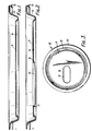
- Figures 10 to 13 illustrate a modified embodiment in which a can end 10 is pierced with two circular apertures, namely a pouring aperture 30 and a smaller vent aperture 31, each surrounded by a downturned flange 32,33, respectively, extending at 90 0 to the plane of the panel portion 11 and having a flat end surface 34.
- the plastics closure 35 is injection moulded as described above with reference to Figure 4 so as to have two plug portions 36,37 fitting respectively into the apertures 30,31 and surrounded on the underside of the can end 10 by surrounding portions 38.
- the plastics material encloses each flange 32,33 totally, with a residual thickness below the flat end surface 34 in the range from 0.08 to 0.5 mm, preferably from 0.15 to 0.40 mm.
- the closure 35 also incorporates a ring pull 39 which in this case lies on the right hand side of the plug portions (as seen in Figures 11, 12 and 13) but is connected to them at the left hand end, i.e. close to the pouring aperture plug 36.
- the opening procedure accordingly starts at the left-hand side, as shown in Figure 13, with shearing of the plug 36 from its surrounding portion 38 to open the pouring aperture 30, followed by shearing of the plug 37 from its surrounding portion 38 to open the vent aperture 31.
- the use of two apertures enables one to use apertures of smaller area and smaller radii of curvature than in the embodiment of Figures 2 to 9, and thereby reduces the tendency to distort as a result of creep under tension when subject to internal pressure in the can, so that a material with a slightly lower creep resistance than nylon can be used, such as a polypropylene.
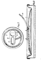
- FIG. 14 to 16 A modified form of single-aperture can end is illustrated in Figures 14 to 16.
- This form differs from that described above with reference to Figures 2 to 9 in that it has a pear-shaped aperture 151, having a pouring end 152 of larger radius than the opposite or venting end 153, and a downturned flange 161 around its periphery.
- the residual thickness 127 of the plastics material of the closure below the flat end of the flange 161 is varied around the periphery of the aperture, while remaining within the range of 0.08 to 0.5 mm.
- the residual thickness 127 is varied in a continuous manner around the left-hand half of the aperture 151, being greatest at the pouring end 152 which has the greater radius of curvature and where the tendency to distort is greatest under tension resulting from internal pressure in the can.
- the increased residual thickness 127 at the pouring end 152 improves the resistance to creep and distortion of the closure, so that a material with a lesser creep resistance than nylon may be used, such as a polypropylene.
- the residual thickness 127 may vary from 0.4 mm at the pouring end 152 to 0.2 mm in the right-hand half of the aperture 151.
- an intermediate portion may have a constant residual thickness of 0.3 mm along the straight convergent sides of the aperture.
- the transition from the thicker to the thinner portion may be gradual, as shown in Figure 16, or may be by way of a step in the lower surface of the plastics material.
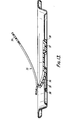
- Figures 17 to 19 illustrate a further embodiment with two apertures, namely a pouring aperture 30 and vent aperture 31 with respective downturned flanges 32,33, as in Figures 10 to 13.
- the pull ring 261 is similar to that of Figures 7 to 9, so as to ensure that the vent aperture 31 is opened first, but is provided with an additional thin lip 262 to facilitate engagement by a finger.
- the residual thickness 127 of the plastics material below the flat end of the flange 32 is continuously varied around the periphery of the pouring aperture 30, as can be seen in Figure 19, while remaining within the range 0.08 to 0.5 mm being greatest in the part of the periphery remote from the vent aperture 31, so as to provide improved resistance to creep where the tendency to distort is greatest.
- a further feature of this embodiment is that a portion 40 of the closure joining plug portions 41,42 filling the two apertures 30,31 acts as a strap to hold the parts of the closure in position when the can end is distorted under internal pressure.
- the residual thickness of the plastics material below the downturned flange may be varied in a stepwise, rather than a continuous manner.
- Figure 20 represents a modification of the embodiment of Figures 17 to 19 and shows a plug portion 43 in the pouring aperture 30 formed with a transverse step 44 so as to result in a stepwise increase in the residual thickness at the left-hand side of the pouring aperture 30, remote from the vent aperture 31.
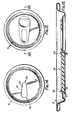
- FIGS 21 to 23 illustrate a modification of the embodiment of. Figures 17 to 19 in which the vent aperture 311 is of substantially smaller dimensions than the vent aperture 31 of Figures 17 to 19, having straight sides joined by curved ends 45,46 of small radius of curvature. No flange is provided around the vent aperture 311.
- the closure shears easily against the end 46 of the vent aperture because the stiffness of the can end remains sufficient to prevent it from bending, due to the small area and sharp curvature of the vent aperture.
- the residual thickness 127 below the flange 32 around the pouring aperture 30 is varied as in the embodiment of Figures 17 to 19. The closure again shears easily at the right hand side of the pouring aperture 30 due to the small residual thickness at this point, while the increased residual thickness at the side remote from the vent aperture provides the necessary resistance to creep.
- Figures 24 and 25 illustrate a modification of the embodiment of Figures 14 to 16, in which the pear-shaped aperture 151 has a flange 162 which extends around the broader end 152 but is discontinued at the narrow end 153 of the aperture, where the need for resistance to creep is minimal.
- the plug portion 154 of the closure can be seen from Figure 25 to provide an increased residual thickness at the broader end 152 of the aperture, as in Figures 14 to 16.
- Figures 26 and 27 illustrate a further modification of the embodiment of Figures 14 to 16, in which the pear-shaped aperture 151 has a flange 163 which varies continuously in depth from a maximum at the broader end 152 to zero at the narrow end 153 of the aperture.
- the plug portion 155 in this case is thickened in a stepwise fashion at 156 but otherwise varies in thickness in proportion with the depth of the flange 163, so that the residual thickness below the flange is greater around the broader end 152 but is constant around the narrow end 153 of the aperture.
- the greater depth of the flange 163 at the broader end 152 of the aperture assists the increased residual thickness to provide the necessary resistance to creep.
- the can ends illustrated and described are intended for use on cans for beverages which require thermal processing, i.e. heating to 35 0 C to drive off condensation before shrink-wrapping and/or pasteurisation at 65 0 C, so it is necessary that the plastics material used for the closure should be resistant to softening at temperatures up to 65 0 C.
- the plastics material used for the coating 14 on the underside of the can end is preferably a similar polymer in order to ensure adequate bonding.
- the thickness of the plastics material of the closure is such as to enclose the flange 16 totally but to be capable of shearing against the flat end surface 17 of the flange when the ring pull is pulled to open the closure.
- the optimum dimension for the downturn of the flange to be 0.75 mm, though it may vary from 0.125 mm to 2.5 mm.
- the lateral extent of the surrounding portions 24 and 38 is also important. The preferred lateral extent from the flange of these portions is 1.25 mm though it may vary from 0.125 m to 7.5 mm.
- the residual thickness 27,127 of the plastics material of the closure below the flat surface 17 of the flange 16 is of considerable importance in order to ensure that leakage is prevented but that the plug portion can be sheared off against the flange when the closure is to be opened.
- the optimum residual thickness for shearing is between 0.15 mm and 0.40 mm, though other considerations may make it preferable to use a thickness from 0.08 mm to 0.50 mm.
- the preferred thickness of the ring pull is substantially 1.0 mm, though it may vary from 0.25 mm to 4.3 mm.
- closure according to the invention may be provided with plugs adapted for fitting into apertures of larger diameter than those illustrated in the drawings, e.g. for use on cans for solid or semi-solid food products.
Landscapes
- Engineering & Computer Science (AREA)
- Mechanical Engineering (AREA)
- Manufacturing & Machinery (AREA)
- Closures For Containers (AREA)
- Containers Opened By Tearing Frangible Portions (AREA)
- Compositions Of Macromolecular Compounds (AREA)
- Forging (AREA)
- Injection Moulding Of Plastics Or The Like (AREA)
- Secondary Cells (AREA)
- Details Of Rigid Or Semi-Rigid Containers (AREA)
- Sealing Battery Cases Or Jackets (AREA)
- Spark Plugs (AREA)
- Laminated Bodies (AREA)
Priority Applications (1)
| Application Number | Priority Date | Filing Date | Title |
|---|---|---|---|
| AT86307127T ATE52235T1 (de) | 1985-09-20 | 1986-09-16 | Verfahren zur herstellung eines mit einem plastischen verschluss versehenen dosendeckels aus metall. |
Applications Claiming Priority (2)
| Application Number | Priority Date | Filing Date | Title |
|---|---|---|---|
| GB858523263A GB8523263D0 (en) | 1985-09-20 | 1985-09-20 | Making metal can ends |
| GB8523263 | 1985-09-20 |
Publications (3)
| Publication Number | Publication Date |
|---|---|
| EP0215671A2 true EP0215671A2 (de) | 1987-03-25 |
| EP0215671A3 EP0215671A3 (en) | 1988-05-18 |
| EP0215671B1 EP0215671B1 (de) | 1990-04-25 |
Family
ID=10585488
Family Applications (1)
| Application Number | Title | Priority Date | Filing Date |
|---|---|---|---|
| EP86307127A Expired - Lifetime EP0215671B1 (de) | 1985-09-20 | 1986-09-16 | Verfahren zur Herstellung eines mit einem plastischen Verschluss versehenen Dosendeckels aus Metall |
Country Status (19)
| Country | Link |
|---|---|
| US (2) | US4813837A (de) |
| EP (1) | EP0215671B1 (de) |
| JP (1) | JPS6278050A (de) |
| CN (1) | CN1007232B (de) |
| AT (1) | ATE52235T1 (de) |
| AU (1) | AU585644B2 (de) |
| BR (1) | BR8604497A (de) |
| CA (1) | CA1266838A (de) |
| DE (1) | DE3670618D1 (de) |
| ES (1) | ES2000902A6 (de) |
| GB (2) | GB8523263D0 (de) |
| GR (1) | GR862395B (de) |
| IN (1) | IN167884B (de) |
| MY (1) | MY100035A (de) |
| NO (1) | NO863726L (de) |
| NZ (1) | NZ217628A (de) |
| SU (1) | SU1491328A3 (de) |
| TR (1) | TR22950A (de) |
| ZA (1) | ZA866897B (de) |
Cited By (7)
| Publication number | Priority date | Publication date | Assignee | Title |
|---|---|---|---|---|
| GB2187712B (en) * | 1986-03-11 | 1990-05-23 | Tetra Pak Finance & Trading | Fluid pack and process for the production therof |
| EP0383442A1 (de) * | 1989-02-16 | 1990-08-22 | Cmb Foodcan Plc | Dosendeckel |
| US5045594A (en) * | 1988-06-29 | 1991-09-03 | W. R. Grace & Co.-Conn. | Container closures and sealed containers |
| FR2706866A1 (en) * | 1993-06-22 | 1994-12-30 | Geiger Sarl | Tube with tear-off key and air inlet |
| US6371318B1 (en) | 1997-12-24 | 2002-04-16 | Owens-Illinois Closure Inc. | Plastic closure with compression molded sealing/barrier liner |
| US6399170B1 (en) | 1997-12-24 | 2002-06-04 | Owens-Illinois Closure Inc. | Plastic closure with compression molded barrier liner |
| CN109641679A (zh) * | 2016-07-08 | 2019-04-16 | 罗兰·安德鲁斯 | 容器打开设备、用于容器的闭合装置以及容器 |
Families Citing this family (57)
| Publication number | Priority date | Publication date | Assignee | Title |
|---|---|---|---|---|
| GB8724245D0 (en) * | 1987-10-15 | 1987-11-18 | Metal Box Plc | Metal can ends |
| GB8903631D0 (en) * | 1989-02-17 | 1989-04-05 | Metal Box Plc | Can ends |
| US5119955A (en) * | 1990-05-23 | 1992-06-09 | Granofsky Barry P | Sanitary can closure |
| US5108003A (en) * | 1991-06-10 | 1992-04-28 | Granofsky Barry P | Cover for beverage can |
| USD1011671S1 (en) | 1991-07-02 | 2024-01-16 | Bway Corporation | Container |
| US5253779A (en) * | 1992-01-03 | 1993-10-19 | Lee Gul N | Beverage container having a self-contained pop-up straw assembly |
| GB9510515D0 (en) | 1995-05-24 | 1995-07-19 | Metal Box Plc | Containers |
| USD406236S (en) * | 1995-10-05 | 1999-03-02 | Crown Cork & Seal Technologies Corporation | Can end |
| IT1287126B1 (it) * | 1996-10-31 | 1998-08-04 | Tetra Laval Holdings & Finance | Procedimento e utensili a stampo per lo stampaggio ad iniezione di una parte di materia plastica in un materiale in foglio da imballaggio |
| US6102243A (en) | 1998-08-26 | 2000-08-15 | Crown Cork & Seal Technologies Corporation | Can end having a strengthened side wall and apparatus and method of making same |
| US6561004B1 (en) | 1999-12-08 | 2003-05-13 | Metal Container Corporation | Can lid closure and method of joining a can lid closure to a can body |
| US7380684B2 (en) | 1999-12-08 | 2008-06-03 | Metal Container Corporation | Can lid closure |
| US6499622B1 (en) * | 1999-12-08 | 2002-12-31 | Metal Container Corporation, Inc. | Can lid closure and method of joining a can lid closure to a can body |
| EP1470052B1 (de) * | 1999-12-08 | 2012-09-19 | Ball Corporation | Deckelverschluss für eine metallgetränkedose mit verbesserter stützwand und deckelrille |
| US6588619B2 (en) | 2001-01-22 | 2003-07-08 | Venanzio Cardarelli | Tennis ball container safety shield |
| US6419110B1 (en) * | 2001-07-03 | 2002-07-16 | Container Development, Ltd. | Double-seamed can end and method for forming |
| SE523936C2 (sv) * | 2001-12-19 | 2004-06-01 | Tetra Laval Holdings & Finance | Formsprutningsverktyg samt sätt att formspruta |
| EP1386852A1 (de) * | 2002-07-26 | 2004-02-04 | Crown Cork & Seal Technologies Corporation | Deckelstruktur |
| US6889862B2 (en) * | 2002-09-19 | 2005-05-10 | Ball Corporation | Large opening beverage container |
| DE602005023470D1 (de) * | 2004-07-29 | 2010-10-21 | Ball Corp | Verfahren und vorrichtung zur formung des endverschlusses eines metallbehälters |
| WO2006036934A2 (en) * | 2004-09-27 | 2006-04-06 | Ball Corporation | Container end closure |
| PL1640282T3 (pl) * | 2004-09-28 | 2007-08-31 | Ball Packaging Europe Gmbh | Blaszane wieczko puszki na napój, wyposażone w duży otwór |
| AU2006251211B2 (en) * | 2005-05-25 | 2012-08-16 | Ball Packaging Europe Gmbh | Tin lid with guide posts for a container |
| US7506779B2 (en) * | 2005-07-01 | 2009-03-24 | Ball Corporation | Method and apparatus for forming a reinforcing bead in a container end closure |
| US20080302797A1 (en) * | 2007-06-11 | 2008-12-11 | Evan Ira Phillips | Container |
| USD559680S1 (en) | 2007-06-28 | 2008-01-15 | Ball Corporation | Metallic end closure for a container |
| PL2052984T3 (pl) * | 2007-10-25 | 2011-05-31 | Impress Group Bv | Sposób przygotowywania i formowania wieczka oraz wieczko |
| US20090180999A1 (en) * | 2008-01-11 | 2009-07-16 | U.S. Nutraceuticals, Llc D/B/A Valensa International | Method of preventing, controlling and ameliorating urinary tract infections using cranberry derivative and d-mannose composition |
| US8857644B2 (en) * | 2008-11-26 | 2014-10-14 | B.E. Inventive, Llc | Container |
| WO2011073105A1 (en) * | 2009-12-14 | 2011-06-23 | Tetra Laval Holdings & Finance S.A. | Opening device and method for manufacturing the same, and a packaging material provided with said opening device |
| US8727169B2 (en) | 2010-11-18 | 2014-05-20 | Ball Corporation | Metallic beverage can end closure with offset countersink |
| EP2612822A1 (de) | 2012-01-03 | 2013-07-10 | Anheuser-Busch InBev S.A. | Dose, die eine erste Ausgabeöffnung und eine zweite Belüftungsöffnung und eine einzige Aufreißlasche umfasst |
| CN102849324B (zh) * | 2012-07-13 | 2014-11-05 | 浙江诚信包装材料有限公司 | 易拉罐的封口结构及加工工艺 |
| US9181007B2 (en) | 2013-03-12 | 2015-11-10 | Rexam Beverage Can Company | Beverage can end with vent port |
| USD747649S1 (en) | 2014-01-15 | 2016-01-19 | B.E. Inventive, Llc | Can end |
| USD747199S1 (en) | 2014-01-15 | 2016-01-12 | B.E. Inventive, Llc | Closure for can |
| US9901972B2 (en) | 2014-03-07 | 2018-02-27 | Ball Corporation | End closure with large opening ring pull tab |
| US10632520B2 (en) | 2014-03-07 | 2020-04-28 | Ball Corporation | End closure with large opening ring pull tab |
| CN106180464A (zh) * | 2016-07-28 | 2016-12-07 | 苏州华源包装股份有限公司 | 一种整张原料冲压进行填盖的工艺 |
| CN106077349A (zh) * | 2016-07-29 | 2016-11-09 | 苏州华源包装股份有限公司 | 一种向内盖内复合圆片的结构 |
| CN106077352A (zh) * | 2016-07-29 | 2016-11-09 | 苏州华源包装股份有限公司 | 一种向内盖内塞圆片的结构 |
| CN106077351A (zh) * | 2016-07-29 | 2016-11-09 | 苏州华源包装股份有限公司 | 一种内盖内复合圆片的安装结构 |
| CN106077350A (zh) * | 2016-07-29 | 2016-11-09 | 苏州华源包装股份有限公司 | 一种向内盖内复合圆片的工艺 |
| CN106077348A (zh) * | 2016-07-29 | 2016-11-09 | 苏州华源包装股份有限公司 | 一种整张原料冲压进行填盖的结构 |
| USD917282S1 (en) * | 2017-08-30 | 2021-04-27 | Stolle Machinery Company, Llc | Shell |
| USD917284S1 (en) * | 2017-08-30 | 2021-04-27 | Stolle Machinery Company, Llc | Shell |
| USD917283S1 (en) * | 2017-08-30 | 2021-04-27 | Stolle Machinery Company, Llc | Shell |
| USD917281S1 (en) * | 2017-08-30 | 2021-04-27 | Stolle Machinery Company, Llc | Shell |
| US10518926B2 (en) | 2017-08-30 | 2019-12-31 | Stolle Machinery Company, Llc | Reverse pressure can end |
| US10894630B2 (en) | 2017-08-30 | 2021-01-19 | Stolle Machinery Company, Llc | Pressure can end compatible with standard can seamer |
| US10947002B2 (en) | 2017-08-30 | 2021-03-16 | Stolle Machinery Company, Llc | Reverse pressure can end |
| USD932721S1 (en) * | 2020-02-26 | 2021-10-05 | Bway Corporation | Container ring |
| US12515850B2 (en) | 2019-02-26 | 2026-01-06 | Bway Corporation | Container and seal assembly |
| EP3931120A4 (de) | 2019-02-26 | 2023-01-11 | Bway Corporation | Behälter und dichtungsanordnung |
| USD916590S1 (en) * | 2019-05-17 | 2021-04-20 | Stolle Machinery Company, Llc | Shell |
| USD1015669S1 (en) | 2020-02-26 | 2024-02-20 | Bway Corporation | Container ring |
| DE102020128491A1 (de) * | 2020-10-29 | 2022-05-05 | Top Cap Holding Gmbh | Dosendeckel und Verfahren zum Herstellen eines Dosendeckels |
Family Cites Families (11)
| Publication number | Priority date | Publication date | Assignee | Title |
|---|---|---|---|---|
| US3437227A (en) * | 1968-02-21 | 1969-04-08 | Continental Can Co | Easy opening container |
| GB1393875A (en) * | 1971-08-20 | 1975-05-14 | Metal Box Co Ltd | Container closures |
| BR7105972D0 (pt) * | 1971-09-10 | 1973-04-26 | Toddy Do Brasil Sa | Aperfeicoamentos em tampas para recipientes em geral |
| JPS5422532Y2 (de) * | 1973-08-10 | 1979-08-06 | ||
| US4309952A (en) * | 1977-12-15 | 1982-01-12 | Tokan Kogyo Co., Ltd. | Process for making a container cover member having synthetic resin openable portion |
| US4170314A (en) * | 1978-10-11 | 1979-10-09 | The Continental Group, Inc. | Container closure |
| GB2073646B (en) * | 1980-03-25 | 1983-12-07 | Metal Box Co Ltd | Moulding plastics onto metal sheets |
| ES8307644A1 (es) * | 1981-07-10 | 1983-08-16 | Hunter Thomas Ltd | Perfeccionamientos en cierres para recipientes. |
| US4407424A (en) * | 1982-07-01 | 1983-10-04 | The Continental Group, Inc. | Plastic plug type closure for beverage containers |
| GB8404320D0 (en) * | 1984-02-18 | 1984-03-21 | Metal Box Plc | Closure for container |
| GB8523262D0 (en) * | 1985-09-20 | 1985-10-23 | Metal Box Plc | Metal can end |
-
1985
- 1985-09-20 GB GB858523263A patent/GB8523263D0/en active Pending
-
1986
- 1986-09-09 AU AU62577/86A patent/AU585644B2/en not_active Ceased
- 1986-09-10 ZA ZA866897A patent/ZA866897B/xx unknown
- 1986-09-12 IN IN731/MAS/86A patent/IN167884B/en unknown
- 1986-09-16 EP EP86307127A patent/EP0215671B1/de not_active Expired - Lifetime
- 1986-09-16 DE DE8686307127T patent/DE3670618D1/de not_active Expired - Lifetime
- 1986-09-16 AT AT86307127T patent/ATE52235T1/de not_active IP Right Cessation
- 1986-09-16 GB GB8622261A patent/GB2180520B/en not_active Expired
- 1986-09-17 ES ES8601946A patent/ES2000902A6/es not_active Expired
- 1986-09-18 TR TR507/86A patent/TR22950A/xx unknown
- 1986-09-18 NZ NZ217628A patent/NZ217628A/en unknown
- 1986-09-18 NO NO863726A patent/NO863726L/no unknown
- 1986-09-18 GR GR862395A patent/GR862395B/el unknown
- 1986-09-19 CA CA000518642A patent/CA1266838A/en not_active Expired - Lifetime
- 1986-09-19 JP JP61221757A patent/JPS6278050A/ja active Granted
- 1986-09-19 SU SU864028181A patent/SU1491328A3/ru active
- 1986-09-19 BR BR8604497A patent/BR8604497A/pt not_active IP Right Cessation
- 1986-09-19 CN CN87105251A patent/CN1007232B/zh not_active Expired
- 1986-11-21 MY MYPI86000116A patent/MY100035A/en unknown
-
1988
- 1988-02-25 US US07/163,186 patent/US4813837A/en not_active Expired - Fee Related
- 1988-07-08 US US07/216,473 patent/US4893725A/en not_active Expired - Fee Related
Cited By (11)
| Publication number | Priority date | Publication date | Assignee | Title |
|---|---|---|---|---|
| GB2187712B (en) * | 1986-03-11 | 1990-05-23 | Tetra Pak Finance & Trading | Fluid pack and process for the production therof |
| US5045594A (en) * | 1988-06-29 | 1991-09-03 | W. R. Grace & Co.-Conn. | Container closures and sealed containers |
| EP0383442A1 (de) * | 1989-02-16 | 1990-08-22 | Cmb Foodcan Plc | Dosendeckel |
| FR2706866A1 (en) * | 1993-06-22 | 1994-12-30 | Geiger Sarl | Tube with tear-off key and air inlet |
| US6371318B1 (en) | 1997-12-24 | 2002-04-16 | Owens-Illinois Closure Inc. | Plastic closure with compression molded sealing/barrier liner |
| US6399170B1 (en) | 1997-12-24 | 2002-06-04 | Owens-Illinois Closure Inc. | Plastic closure with compression molded barrier liner |
| US6677016B2 (en) | 1997-12-24 | 2004-01-13 | Owens-Illimois Closure Inc. | Plastic closure with compression molded sealing/barrier liner |
| US6696123B2 (en) | 1997-12-24 | 2004-02-24 | Owens-Illinois Closure Inc. | Plastic closure with compression molded barrier liner |
| US7651651B2 (en) | 1997-12-24 | 2010-01-26 | Rexam Closure Systems Inc. | Plastic closure with compression molded sealing/barrier liner |
| CN109641679A (zh) * | 2016-07-08 | 2019-04-16 | 罗兰·安德鲁斯 | 容器打开设备、用于容器的闭合装置以及容器 |
| CN109641679B (zh) * | 2016-07-08 | 2021-09-10 | 罗兰·安德鲁斯 | 容器打开设备、用于容器的闭合装置以及容器 |
Also Published As
| Publication number | Publication date |
|---|---|
| GB8523263D0 (en) | 1985-10-23 |
| CN1007232B (zh) | 1990-03-21 |
| ES2000902A6 (es) | 1988-03-16 |
| CN86107457A (zh) | 1987-06-17 |
| MY100035A (en) | 1989-06-29 |
| AU6257786A (en) | 1987-03-26 |
| EP0215671B1 (de) | 1990-04-25 |
| US4813837A (en) | 1989-03-21 |
| ATE52235T1 (de) | 1990-05-15 |
| EP0215671A3 (en) | 1988-05-18 |
| US4893725A (en) | 1990-01-16 |
| TR22950A (tr) | 1988-12-09 |
| ZA866897B (en) | 1987-06-24 |
| BR8604497A (pt) | 1987-05-19 |
| NO863726L (no) | 1987-03-23 |
| GB2180520A (en) | 1987-04-01 |
| JPH0329671B2 (de) | 1991-04-24 |
| DE3670618D1 (de) | 1990-05-31 |
| JPS6278050A (ja) | 1987-04-10 |
| IN167884B (de) | 1991-01-05 |
| AU585644B2 (en) | 1989-06-22 |
| GB2180520B (en) | 1989-08-31 |
| SU1491328A3 (ru) | 1989-06-30 |
| NO863726D0 (no) | 1986-09-18 |
| CA1266838A (en) | 1990-03-20 |
| GR862395B (en) | 1987-01-20 |
| NZ217628A (en) | 1988-02-29 |
| GB8622261D0 (en) | 1986-10-22 |
Similar Documents
| Publication | Publication Date | Title |
|---|---|---|
| EP0215671B1 (de) | Verfahren zur Herstellung eines mit einem plastischen Verschluss versehenen Dosendeckels aus Metall | |
| US5830398A (en) | Method for forming container closure | |
| US4513876A (en) | Container lid with an opener device | |
| EP1425225B1 (de) | Dosenende | |
| EP0220820B1 (de) | Blechkanne mit Kunststoffverschluss | |
| US4733793A (en) | System for forming an opening in a container end member | |
| WO1982003612A1 (en) | Closure cap for beverage containers | |
| US4804104A (en) | System for forming an opening in a container end member | |
| EP1080020A2 (de) | Dünnwändige kunststoffflasche, verschlusskappe und abfüllverfahren | |
| US4735336A (en) | Opener for a packaging container | |
| IL47332A (en) | Easy-opening container component and method and apparatus for producing it | |
| GB2053134A (en) | Easy-open can end closure | |
| US4828135A (en) | Cover for a can-shaped container | |
| US3931909A (en) | Push-in easy-opening closures | |
| CA2009056A1 (en) | Can end | |
| US5114507A (en) | Closure device for a packaging container | |
| US20060280846A1 (en) | Food container | |
| US4043481A (en) | Scored metal flap areas | |
| WO1999067150A1 (en) | Beverage container having a resealable closure | |
| US5147058A (en) | Easily opened metal lid for a container | |
| US4274351A (en) | Can end closure | |
| US3322297A (en) | Can with integral pull tab | |
| US20040079654A1 (en) | Packaging container | |
| WO1998054058A1 (en) | Pull-open closure for lids of cans of drinks | |
| GB2229697A (en) | Easy open can end |
Legal Events
| Date | Code | Title | Description |
|---|---|---|---|
| PUAI | Public reference made under article 153(3) epc to a published international application that has entered the european phase |
Free format text: ORIGINAL CODE: 0009012 |
|
| 17P | Request for examination filed |
Effective date: 19861001 |
|
| AK | Designated contracting states |
Kind code of ref document: A2 Designated state(s): AT BE CH DE FR GB IT LI LU NL SE |
|
| PUAL | Search report despatched |
Free format text: ORIGINAL CODE: 0009013 |
|
| AK | Designated contracting states |
Kind code of ref document: A3 Designated state(s): AT BE CH DE FR GB IT LI LU NL SE |
|
| RAP1 | Party data changed (applicant data changed or rights of an application transferred) |
Owner name: MB GROUP PLC |
|
| 17Q | First examination report despatched |
Effective date: 19890328 |
|
| RAP1 | Party data changed (applicant data changed or rights of an application transferred) |
Owner name: CMB PACKAGING (UK) LIMITED |
|
| GRAA | (expected) grant |
Free format text: ORIGINAL CODE: 0009210 |
|
| AK | Designated contracting states |
Kind code of ref document: B1 Designated state(s): AT BE CH DE FR IT LI LU NL SE |
|
| REF | Corresponds to: |
Ref document number: 52235 Country of ref document: AT Date of ref document: 19900515 Kind code of ref document: T |
|
| ITF | It: translation for a ep patent filed | ||
| REF | Corresponds to: |
Ref document number: 3670618 Country of ref document: DE Date of ref document: 19900531 |
|
| ET | Fr: translation filed | ||
| PGFP | Annual fee paid to national office [announced via postgrant information from national office to epo] |
Ref country code: BE Payment date: 19900625 Year of fee payment: 5 |
|
| PGFP | Annual fee paid to national office [announced via postgrant information from national office to epo] |
Ref country code: LU Payment date: 19900704 Year of fee payment: 5 |
|
| PGFP | Annual fee paid to national office [announced via postgrant information from national office to epo] |
Ref country code: CH Payment date: 19900905 Year of fee payment: 5 |
|
| PGFP | Annual fee paid to national office [announced via postgrant information from national office to epo] |
Ref country code: SE Payment date: 19900907 Year of fee payment: 5 |
|
| PGFP | Annual fee paid to national office [announced via postgrant information from national office to epo] |
Ref country code: AT Payment date: 19900926 Year of fee payment: 5 |
|
| ITTA | It: last paid annual fee | ||
| PG25 | Lapsed in a contracting state [announced via postgrant information from national office to epo] |
Ref country code: LU Free format text: LAPSE BECAUSE OF NON-PAYMENT OF DUE FEES Effective date: 19900930 |
|
| PLBE | No opposition filed within time limit |
Free format text: ORIGINAL CODE: 0009261 |
|
| STAA | Information on the status of an ep patent application or granted ep patent |
Free format text: STATUS: NO OPPOSITION FILED WITHIN TIME LIMIT |
|
| 26N | No opposition filed | ||
| PG25 | Lapsed in a contracting state [announced via postgrant information from national office to epo] |
Ref country code: AT Effective date: 19910916 |
|
| PG25 | Lapsed in a contracting state [announced via postgrant information from national office to epo] |
Ref country code: SE Effective date: 19910917 |
|
| PG25 | Lapsed in a contracting state [announced via postgrant information from national office to epo] |
Ref country code: LI Effective date: 19910930 Ref country code: CH Effective date: 19910930 Ref country code: BE Effective date: 19910930 |
|
| BERE | Be: lapsed |
Owner name: CMB PACKAGING (UK) LTD Effective date: 19910930 |
|
| REG | Reference to a national code |
Ref country code: CH Ref legal event code: PL |
|
| PGFP | Annual fee paid to national office [announced via postgrant information from national office to epo] |
Ref country code: FR Payment date: 19920807 Year of fee payment: 7 |
|
| PGFP | Annual fee paid to national office [announced via postgrant information from national office to epo] |
Ref country code: DE Payment date: 19920819 Year of fee payment: 7 |
|
| PGFP | Annual fee paid to national office [announced via postgrant information from national office to epo] |
Ref country code: NL Payment date: 19920930 Year of fee payment: 7 |
|
| PG25 | Lapsed in a contracting state [announced via postgrant information from national office to epo] |
Ref country code: NL Effective date: 19940401 |
|
| NLV4 | Nl: lapsed or anulled due to non-payment of the annual fee | ||
| PG25 | Lapsed in a contracting state [announced via postgrant information from national office to epo] |
Ref country code: FR Free format text: LAPSE BECAUSE OF NON-PAYMENT OF DUE FEES Effective date: 19940531 |
|
| PG25 | Lapsed in a contracting state [announced via postgrant information from national office to epo] |
Ref country code: DE Effective date: 19940601 |
|
| REG | Reference to a national code |
Ref country code: FR Ref legal event code: ST |
|
| EUG | Se: european patent has lapsed |
Ref document number: 86307127.0 Effective date: 19920408 |
|
| PG25 | Lapsed in a contracting state [announced via postgrant information from national office to epo] |
Ref country code: IT Free format text: LAPSE BECAUSE OF NON-PAYMENT OF DUE FEES;WARNING: LAPSES OF ITALIAN PATENTS WITH EFFECTIVE DATE BEFORE 2007 MAY HAVE OCCURRED AT ANY TIME BEFORE 2007. THE CORRECT EFFECTIVE DATE MAY BE DIFFERENT FROM THE ONE RECORDED. Effective date: 20050916 |