EP0215712A1 - Lese- und Schreibeinrichtung für Identitätskarten - Google Patents
Lese- und Schreibeinrichtung für Identitätskarten Download PDFInfo
- Publication number
- EP0215712A1 EP0215712A1 EP86401983A EP86401983A EP0215712A1 EP 0215712 A1 EP0215712 A1 EP 0215712A1 EP 86401983 A EP86401983 A EP 86401983A EP 86401983 A EP86401983 A EP 86401983A EP 0215712 A1 EP0215712 A1 EP 0215712A1
- Authority
- EP
- European Patent Office
- Prior art keywords
- card
- guide path
- magnetic
- reader
- parallel
- Prior art date
- Legal status (The legal status is an assumption and is not a legal conclusion. Google has not performed a legal analysis and makes no representation as to the accuracy of the status listed.)
- Granted
Links
Images

Classifications
-
- G—PHYSICS
- G06—COMPUTING OR CALCULATING; COUNTING
- G06K—GRAPHICAL DATA READING; PRESENTATION OF DATA; RECORD CARRIERS; HANDLING RECORD CARRIERS
- G06K7/00—Methods or arrangements for sensing record carriers, e.g. for reading patterns
- G06K7/08—Methods or arrangements for sensing record carriers, e.g. for reading patterns by means detecting the change of an electrostatic or magnetic field, e.g. by detecting change of capacitance between electrodes
- G06K7/082—Methods or arrangements for sensing record carriers, e.g. for reading patterns by means detecting the change of an electrostatic or magnetic field, e.g. by detecting change of capacitance between electrodes using inductive or magnetic sensors
- G06K7/083—Methods or arrangements for sensing record carriers, e.g. for reading patterns by means detecting the change of an electrostatic or magnetic field, e.g. by detecting change of capacitance between electrodes using inductive or magnetic sensors inductive
- G06K7/084—Methods or arrangements for sensing record carriers, e.g. for reading patterns by means detecting the change of an electrostatic or magnetic field, e.g. by detecting change of capacitance between electrodes using inductive or magnetic sensors inductive sensing magnetic material by relative movement detecting flux changes without altering its magnetised state
-
- G—PHYSICS
- G06—COMPUTING OR CALCULATING; COUNTING
- G06K—GRAPHICAL DATA READING; PRESENTATION OF DATA; RECORD CARRIERS; HANDLING RECORD CARRIERS
- G06K13/00—Conveying record carriers from one station to another, e.g. from stack to punching mechanism
- G06K13/02—Conveying record carriers from one station to another, e.g. from stack to punching mechanism the record carrier having longitudinal dimension comparable with transverse dimension, e.g. punched card
- G06K13/08—Feeding or discharging cards
-
- G—PHYSICS
- G06—COMPUTING OR CALCULATING; COUNTING
- G06K—GRAPHICAL DATA READING; PRESENTATION OF DATA; RECORD CARRIERS; HANDLING RECORD CARRIERS
- G06K7/00—Methods or arrangements for sensing record carriers, e.g. for reading patterns
- G06K7/01—Details
- G06K7/015—Aligning or centering of the sensing device with respect to the record carrier
Definitions
- the present invention relates to an identification card encoder reader.
- the primary object of the present invention is to seek to overcome the drawbacks of the above prior art, while proposing a card reader which is economically less expensive to produce.
- the card reader comprising an entry airlock, a fixed guide path provided with card drive means and a station for reading the magnetic strip of the card, consisting of one side of the guide path by a read head and on the other side of a drive roller
- the read heads of the magnetic tracks comprise two blocks of at least one magnetic head, pivotally mounted along axes parallel to the direction of the guide track, at each end of two spreaders located on either side of the heads, said spreaders being mounted for rotation along a third axis parallel to the direction of the guide track on a fork itself mounted pivoting along a fourth axis parallel to the direction of the guide path, said fork being urged by elastic means so as to permanently maintain the heads in abutment on the card during its passage.
- the drive means are constituted because rollers completely covering in their widths all the elements of the magnetic heads which offer mechanical resistance to the advancement of the card, in order to avoid the creation of a parasitic torque oblique direction with respect to the rectilinear trajectory sought and parallel to the predefined path of the reader.
- a second object of the invention is to overcome the above drawbacks.
- the reader shutter comprises baffles constituted by teeth.
- the entry airlock includes coding means.
- the reader comprises, in the extension of the guide path, an integrated circuit card reading station mounted so as to close the guide path and to retract in the event of confiscation, to free the insertion passage into a confiscation bin.
- the retraction of the read head for an integrated circuit is controlled by an electromagnet.
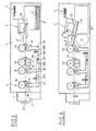
- the reader consists successively of an entry airlock (1), a guide path (2) in which a card (9), not shown, flows driven by drive means (3) ) in the direction of a read head (4) of the magnetic strip of the identification card (9) and subsequently in the direction of a station (5) for reading and writing the integrated circuit of the identification card (9).
- This reader therefore makes it possible to accommodate magnetic stripe cards, integrated circuit cards, or mixed cards comprising both the magnetic stripe and the integrated circuit.
- This treatment station (5) is pivotally mounted around an axis (50) so as to be able to be actuated by an electromagnet (7) which allows it to switch between two positions L, C one, L, corresponding to reading the information contained by the integrated circuit, the other C corresponding to the confiscation position of a card.
- the drive device (3) consists of a series of four drive rollers (30, 31, 32, 33), against which the card is applied by countergalets (34, 35, 36), and the read heads (4).
- the counter-bars (34, 35, 36) are mounted on L-arms respectively (37, 38, 39).
- the countergalets (35, 36) surrounding the read heads (4) are mounted on arms (38; 39) mechanically linked by a known device, consisting of a pin (381) and a finger (391) so that the passage of the card between the rollers (35 and 31) causes the spacing of the rollers (36 and 33), this to avoid braking of the card at the exit of the read head, when the latter occurs between the two rollers (33 and 36).
- the confiscated cards are introduced into a bin (36).
- the confiscated cards are introduced into a confiscation bin (8). At the entrance, the cards are slid into the cone-shaped opening (10) and pushed towards the shutter (11) by the customer.
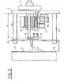
- FIG. 2 represents a view in the direction of movement of the cards of the reader without its entry airlock.
- the reader consists of a plate (6) which supports the various elements. This plate supports spacers (60, 61) at the end of which a plate (62) is mounted, supporting the printed circuit (64).
- the plate (6) supports spacers (63) which keep the guide path (2) at a distance b.
- the guide path is formed on the one hand, by a fork having teeth (21, 20) and whose entry is in the extension of the plane separating the drive roller (32) from the magnetic head (4), d on the other hand by the rollers (30 to 33) and the countergalets (34 to 36).
- the drive roller (32) has a minimum width (d) which covers at least entirely in their widths (e), all the elements (4) of the magnetic reading heads coming into contact with the magnetic cards in order to avoid the creation of a parasitic couple and of oblique direction with respect to the rectilinear trajectory sought and parallel to the predefined path of the reader.
- This assembly (4) comprises three read heads (40, 41, 42) arranged in a single block and a fourth read head (43) mounted by itself.
- This set of heads (4) is mounted as shown in FIG (4A) by means of two spreaders (44) arranged on either side of the heads (40 to 43) and by means of a support fork ( 45).
- the head (43) is articulated on the two spreaders (44) by means of an axis (440) located at a first end of the spreaders and parallel to the direction of the guide path, while the heads (40 to 42) joined together in a single sub-assembly are articulated around an axis (441) supported at the second end of the two spreaders (44) and parallel to the axis (440).
- the ends of the support fork (45) support an axis (450) which passes through the middle of the two spreaders so that they are articulated on the fork (45).
- This fork (45) is articulated around an axis (490) which is integral with two flanges (49), arranged on either side of the heads, and integral with the plate (6).
- the fork (45) has an L-shaped profile which comprises, at the end of the branch (453) not supporting the pivot axis (450), a stud (451) which crosses the plate (6) in a hole (61) formed therein.
- a washer (60) integral with the plate (6) allows a spring (452) passing through the hole (61) to rest on this washer and on the end of the arm (453) of the fork (45) .
- a nut (46) allows by screwing on the stud (451) to adjust the clearance between the heads and the motor roller which is opposite them.
- the rollers are mounted by means of ball bearings on the drive shafts, themselves driven by an M motor (fig. 5) via a system belt (not shown) and pulley P (fig. 2).
- the various motor components, magnetic read heads, integrated circuit read head, locking device are controlled by an electronic card which is mounted integral with the spacers (60 and 61).
- FIG. 4B makes it possible to highlight the advantage of such a mounting of the magnetic read heads.
- a deformed card (9) is still read correctly by the read heads which, thanks to the articulation system of the fork (45) and the rudder bar, apply to the magnetic tracks corresponding.
- This system allows when the deformation of the card is due to the wear of the drive roller '(32) to have a correct reading.
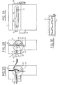
- the entry airlock (1) which is removably mounted relative to the plate (6) is made up as can be seen in FIG. 3A to 3C of a frustoconical opening (10) which ends in its part the narrower giving access to the guide path (2) by a slot having an asymmetrical stall (100) so as to constitute a polarizing means for magnetic cards provided with embossing.
- a magnetic head or other detection system (12) which makes it possible to detect a magnetic track.
- a switch (14) which makes it possible to detect the width of the cards inserted.
- a flap (11) mounted on an axis of rotation (114), at one end of which is a disc (110) integral with this axis (114).
- a spring (111) one end of which is made integral with the casing of the entry airlock (1) and the other end of which is integral with a pin (112) which is itself integral with the disc (110), makes it possible to return the shutter (11) to its position for closing the guide path (2 ).
- a second fixed flap (13) cooperates with the first movable flap (11).
- the two flaps are provided with complementary teeth so as to constitute anti-fraud baffles.
- the disc (110) is provided with an opening which allows the introduction of a locking finger (113), itself integral with the plunger core of an electromagnet not shown in the figure.
- a device (15) constituted by any means known to those skilled in the art makes it possible to detect the locking of the disc.
- This device (15) may be, for example, a switch which will detect the position of the plunger core of the electromagnet.
- the control circuit causes the unlocking of the disc (110) by withdrawal of the finger (113 ) and the card pushed by the customer can tilt the shutter (11).
- the entry airlock (1) being of dimension smaller than the length of the card it will pass through the entry airlock and will be taken between the drive roller (30) and its countergalet (34) and driven by the device mounted on the plate (6).
- FIG. 3D makes it possible to highlight the advantage of the device for closing the airlock during an attempted fraud.
- This figure shows a sheet of flexible son (90) connected to a bank card (9) which comprises at least one microprocessor or integrated circuit system.
- This layer of flexible wires (90) is intended to establish a connection between the contact block (5) allowing access to the computer system of the bank and a fraud device designed by the fraudster.
- the shutter baffle system prevents the disc (110) from returning to its closed position and consequently the introduction of the locking finger (113) into the orifice (115).
- the device will not allow any transaction and therefore the fraudster will not be able to access information from the banking system.
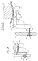
- FIG. 5 represents a card (9) which has been introduced by the drive roller (33) and its counter roller (36) in the slot made in the reading device (5) for integrated circuit cards.
- This device comprises a movable block (51) supporting at its lower part a series of contact blocks (52) and a rubber ring (56) placed in a groove so as to come to press on the card (9) when the block reading (51) is in the working position, represented by reference II.
- This reading unit (51) is movably mounted in a support part (55) articulated around a pivot axis (50), itself integral with the plate (6).
- This support piece (55) has a lower lip (551) inside which is placed a return spring (54), one end of which is fixed to the free or front end of the lower lip (551) and the the other end is fixed to the end of a lug (53) placed at the rear lower part of the reading unit (51).
- a ribbon flexible (57) makes it possible to make the electrical connection between the contacts (52) and the device for processing the information contained by the integrated circuit of the card.
- a metal piece (552) in the form of a pallet secured to the support (55) allows the core of an electromagnet (7) to attract the reading assembly in a high position tilted around the axis (50), position which frees access to a confiscation box (8) of the cards (9), (as shown in FIG. 6).
- Photoelectric detectors (57, 58) placed on the path of the card make it possible to know its position and the logic control circuit to cause the various actions necessary for the operation of the reader.
- the reading station for an integrated circuit and of the card confiscation device will now be explained with the aid of FIGS. 5 and 6.
- the card passes through the entry airlock.
- (1) passes to the station for reading the magnetic strip (4) and is driven by the rollers to the station (5) for reading the integrated circuit.
- the card entrained by the rollers (32 and 33) abuts against the lug (53) of the reading unit (51) which is in position I of FIG. 5.
- the card (9) pushed by the roller drive (33) causes the displacement of the reading unit (51) to bring it against the action of the return spring (54) in the working position 2.
- the contacts (52) come into place in face of the contact pads of the integrated circuit mounted on the card (9).
- the motor M for driving the rollers (30 to 33) is stopped by the action of the reading unit (51) which, when it reaches the end of its travel, commands a switch (not shown) when it reaches its position II.
- the engine is started in the opposite direction and the card (9) is driven in the opposite direction by the rollers to be returned to its owner.
- the device concludes that the card must be confiscated, it proceeds as follows.
- the order to start the drive rollers is sent to the reader and the direction of rotation of the roller ( 33) is inverted to extract the card (9) from the housing defined between the lip (551) and the underside of the block (51) carrying the contacts (52). If the card is to be confiscated as soon as the photoelectric detector (58) placed between the roller (36) and the block (5), detects the absence of the card, that is to say when it located at the magnetic reading station, the logic of the electronic circuit controls the supply of the electromagnet (7) which causes the tilting of the block (5) in the confiscation position shown in Figure 6.
- the block (5) having been tilted the direction of rotation of the rollers is again reversed and the card (9) is driven by the rollers (32 and 33), in the direction of the confiscation tank (8) so as to bring the card (9 ) in the confiscation bin (8).
Landscapes
- Engineering & Computer Science (AREA)
- Physics & Mathematics (AREA)
- General Physics & Mathematics (AREA)
- Theoretical Computer Science (AREA)
- Artificial Intelligence (AREA)
- Computer Vision & Pattern Recognition (AREA)
- Conveying Record Carriers (AREA)
- Control Of Vending Devices And Auxiliary Devices For Vending Devices (AREA)
- Credit Cards Or The Like (AREA)
- Radar Systems Or Details Thereof (AREA)
- Automatic Analysis And Handling Materials Therefor (AREA)
Priority Applications (1)
| Application Number | Priority Date | Filing Date | Title |
|---|---|---|---|
| AT86401983T ATE58254T1 (de) | 1985-09-12 | 1986-09-10 | Lese- und schreibeinrichtung fuer identitaetskarten. |
Applications Claiming Priority (2)
| Application Number | Priority Date | Filing Date | Title |
|---|---|---|---|
| FR8513558 | 1985-09-12 | ||
| FR8513558A FR2587131B1 (fr) | 1985-09-12 | 1985-09-12 | Lecteur encodeur de carte d'identification |
Publications (2)
| Publication Number | Publication Date |
|---|---|
| EP0215712A1 true EP0215712A1 (de) | 1987-03-25 |
| EP0215712B1 EP0215712B1 (de) | 1990-11-07 |
Family
ID=9322858
Family Applications (1)
| Application Number | Title | Priority Date | Filing Date |
|---|---|---|---|
| EP86401983A Expired - Lifetime EP0215712B1 (de) | 1985-09-12 | 1986-09-10 | Lese- und Schreibeinrichtung für Identitätskarten |
Country Status (8)
| Country | Link |
|---|---|
| US (1) | US4806744A (de) |
| EP (1) | EP0215712B1 (de) |
| JP (1) | JPH0746369B2 (de) |
| AT (1) | ATE58254T1 (de) |
| CA (1) | CA1276719C (de) |
| DE (1) | DE3675484D1 (de) |
| FR (1) | FR2587131B1 (de) |
| HK (1) | HK69895A (de) |
Cited By (2)
| Publication number | Priority date | Publication date | Assignee | Title |
|---|---|---|---|---|
| CH682775A5 (fr) * | 1990-03-23 | 1993-11-15 | Landis & Gyr Communications Su | Lecteur de carte. |
| WO2005015484A1 (ja) | 2003-08-11 | 2005-02-17 | Omron Corporation | カード情報読み取り装置 |
Families Citing this family (22)
| Publication number | Priority date | Publication date | Assignee | Title |
|---|---|---|---|---|
| US4871905A (en) * | 1987-10-09 | 1989-10-03 | Omron Tateisi Electronics Co. | IC card reader/writer |
| DE3916812A1 (de) * | 1988-10-19 | 1990-04-26 | Landis & Gyr Ag | Vorrichtung zur aufnahme und kontaktierung von karten, die einen elektronischen schaltkreis enthalten |
| DE3922210A1 (de) * | 1989-07-06 | 1991-01-17 | Standard Elektrik Lorenz Ag | Kartenleser |
| AU635859B2 (en) * | 1990-08-31 | 1993-04-01 | Mitsubishi Jukogyo Kabushiki Kaisha | Cards processor |
| US5317138A (en) * | 1991-02-20 | 1994-05-31 | Olympus Optical Co., Ltd. | Information recording and or reproducing apparatus for use in hybrid type information recording medium |
| US5191198A (en) * | 1991-03-22 | 1993-03-02 | Transaction Technology, Inc. | Gimbal card reader |
| FR2692704B1 (fr) * | 1992-06-22 | 1998-01-16 | Alcatel Radiotelephone | Lecteur de carte a puce. |
| US5309176A (en) * | 1992-08-25 | 1994-05-03 | Sci Systems, Inc. | Airline ticket printer with stepper motor for selectively engaging print head and platen |
| JP3156455B2 (ja) * | 1993-08-10 | 2001-04-16 | 富士通株式会社 | 冊子状媒体の磁気データ処理機構及び冊子状媒体処理装置 |
| US5965862A (en) * | 1994-10-18 | 1999-10-12 | Seiko Epson Corporation | Information detection apparatus and method for printing on a medium and for reading information recorded on the medium |
| US5742422A (en) * | 1995-09-19 | 1998-04-21 | Inspex, Inc. | Adjustable fourier mask |
| US6879391B1 (en) | 1999-05-26 | 2005-04-12 | Kla-Tencor Technologies | Particle detection method and apparatus |
| ES2160066B2 (es) * | 1999-08-18 | 2002-07-16 | Jofemar Sa | Selector de monedas mejorado. |
| DE10025394C2 (de) * | 2000-05-23 | 2003-04-17 | Wincor Nixdorf Int Gmbh | Vorrichtung zur geordneten Ablage von ID-Karten |
| DE10039699C2 (de) * | 2000-08-14 | 2003-12-04 | Wincor Nixdorf Int Gmbh | Vorrichtung zum Bearbeiten von Wettscheinen |
| AU2002227297A1 (en) * | 2000-12-08 | 2002-06-18 | Martin S Silverman | Dynamic virtual magnetic stripe |
| US20040035942A1 (en) * | 2001-12-07 | 2004-02-26 | Silverman Martin S. | Dynamic virtual magnetic stripe |
| US7299984B2 (en) * | 2003-08-21 | 2007-11-27 | Pitney Bowes Inc. | Postage indicia including encoded ink characteristic data |
| US8484671B1 (en) | 2003-10-07 | 2013-07-09 | The Directv Group, Inc. | Receiver interface with multiple access cards |
| US6908241B1 (en) * | 2004-03-16 | 2005-06-21 | Card Technology | Card processing system with combined magnetic encoder and card flipper |
| JP4619204B2 (ja) * | 2005-06-17 | 2011-01-26 | 株式会社ユニバーサルエンターテインメント | 紙幣処理装置 |
| US8985464B2 (en) | 2012-10-08 | 2015-03-24 | Carlos Tovar | Payment card storage apparatus and tab management system |
Citations (8)
| Publication number | Priority date | Publication date | Assignee | Title |
|---|---|---|---|---|
| US3296605A (en) * | 1962-09-13 | 1967-01-03 | Monroe Calculating Machine | Magnetic card reader and transport |
| US3704360A (en) * | 1970-04-15 | 1972-11-28 | Bruce R Mcfadden | Card reader |
| US3909595A (en) * | 1974-08-08 | 1975-09-30 | Diebold Inc | Entry gate construction for credit card actuated automatic remote banking equipment |
| DE2555213A1 (de) * | 1975-11-12 | 1977-05-26 | Sodeco Compteurs De Geneve | Vorrichtung zur sicherung von muenzkassierautomaten gegen betruegerische handlungen |
| FR2356206A1 (fr) * | 1976-06-25 | 1978-01-20 | Siemens Ag | Appareil de lecture ou d'ecriture pour cartes pourvues d'un support de donnees magnetique |
| US4167664A (en) * | 1978-01-20 | 1979-09-11 | Amp Incorporated | Adjustable read head assembly |
| US4298116A (en) * | 1979-10-17 | 1981-11-03 | Coin Acceptors, Inc. | String detector for a coin-selecting device |
| EP0134110A2 (de) * | 1983-08-01 | 1985-03-13 | Oki Electric Industry Company, Limited | Lese- und Schreibvorrichtung für Identifizierungskarten |
Family Cites Families (7)
| Publication number | Priority date | Publication date | Assignee | Title |
|---|---|---|---|---|
| US3836753A (en) * | 1971-12-05 | 1974-09-17 | Amp Inc | Magnetic card reader |
| FR2294491A1 (fr) * | 1974-12-11 | 1976-07-09 | Honeywell Bull Soc Ind | Appareil de traitement de documents |
| US4358103A (en) * | 1977-02-04 | 1982-11-09 | Canon Kabushiki Kaisha | Magnetic card transporting apparatus |
| US4181920A (en) * | 1978-03-27 | 1980-01-01 | Cubic Western Data | Magnetic ticket encoding transport |
| JPS59177065U (ja) * | 1983-05-12 | 1984-11-27 | オムロン株式会社 | 磁気ヘツドの保持装置 |
| GB8319865D0 (en) * | 1983-07-22 | 1983-08-24 | Access Control Developments Lt | Ticket reading device |
| US4616128A (en) * | 1984-01-30 | 1986-10-07 | Cubic Western Data | Mechanism to maintain contact between a magnetically-encoded card and a magnetic transducer surface |
-
1985
- 1985-09-12 FR FR8513558A patent/FR2587131B1/fr not_active Expired
-
1986
- 1986-09-10 JP JP61213701A patent/JPH0746369B2/ja not_active Expired - Lifetime
- 1986-09-10 AT AT86401983T patent/ATE58254T1/de not_active IP Right Cessation
- 1986-09-10 EP EP86401983A patent/EP0215712B1/de not_active Expired - Lifetime
- 1986-09-10 DE DE8686401983T patent/DE3675484D1/de not_active Expired - Lifetime
- 1986-09-12 CA CA000518083A patent/CA1276719C/fr not_active Expired - Lifetime
- 1986-09-12 US US06/906,495 patent/US4806744A/en not_active Expired - Lifetime
-
1995
- 1995-05-04 HK HK69895A patent/HK69895A/xx not_active IP Right Cessation
Patent Citations (8)
| Publication number | Priority date | Publication date | Assignee | Title |
|---|---|---|---|---|
| US3296605A (en) * | 1962-09-13 | 1967-01-03 | Monroe Calculating Machine | Magnetic card reader and transport |
| US3704360A (en) * | 1970-04-15 | 1972-11-28 | Bruce R Mcfadden | Card reader |
| US3909595A (en) * | 1974-08-08 | 1975-09-30 | Diebold Inc | Entry gate construction for credit card actuated automatic remote banking equipment |
| DE2555213A1 (de) * | 1975-11-12 | 1977-05-26 | Sodeco Compteurs De Geneve | Vorrichtung zur sicherung von muenzkassierautomaten gegen betruegerische handlungen |
| FR2356206A1 (fr) * | 1976-06-25 | 1978-01-20 | Siemens Ag | Appareil de lecture ou d'ecriture pour cartes pourvues d'un support de donnees magnetique |
| US4167664A (en) * | 1978-01-20 | 1979-09-11 | Amp Incorporated | Adjustable read head assembly |
| US4298116A (en) * | 1979-10-17 | 1981-11-03 | Coin Acceptors, Inc. | String detector for a coin-selecting device |
| EP0134110A2 (de) * | 1983-08-01 | 1985-03-13 | Oki Electric Industry Company, Limited | Lese- und Schreibvorrichtung für Identifizierungskarten |
Non-Patent Citations (1)
| Title |
|---|
| IBM TECHNICAL DISCLOSURE BULLETIN, vol. 20, no. 10, mars 1978, pages 4091,4092, New York, US; P. LEE: "Encoded magnetic stripe detector with decision window" * |
Cited By (3)
| Publication number | Priority date | Publication date | Assignee | Title |
|---|---|---|---|---|
| CH682775A5 (fr) * | 1990-03-23 | 1993-11-15 | Landis & Gyr Communications Su | Lecteur de carte. |
| WO2005015484A1 (ja) | 2003-08-11 | 2005-02-17 | Omron Corporation | カード情報読み取り装置 |
| EP1655689A4 (de) * | 2003-08-11 | 2009-04-22 | Omron Tateisi Electronics Co | Karteninformationsleseeinrichtung |
Also Published As
| Publication number | Publication date |
|---|---|
| JPS6266386A (ja) | 1987-03-25 |
| DE3675484D1 (de) | 1990-12-13 |
| FR2587131A1 (fr) | 1987-03-13 |
| CA1276719C (fr) | 1990-11-20 |
| JPH0746369B2 (ja) | 1995-05-17 |
| HK69895A (en) | 1995-05-12 |
| US4806744A (en) | 1989-02-21 |
| EP0215712B1 (de) | 1990-11-07 |
| FR2587131B1 (fr) | 1987-11-20 |
| ATE58254T1 (de) | 1990-11-15 |
Similar Documents
| Publication | Publication Date | Title |
|---|---|---|
| EP0215712B1 (de) | Lese- und Schreibeinrichtung für Identitätskarten | |
| EP0218504B1 (de) | Verfahren zur Beschlagnahme einer Karte in einer kombinierten Abtasteinrichtung und kombinierte Abtasteinrichtung | |
| EP1295727B1 (de) | Thermische Druckvorrichtung zum Öffnen und Verriegeln | |
| EP0339059B1 (de) | Vorrichtung zum automatischen ausgeben von gegenständen | |
| CH651807A5 (fr) | Dispositif d'asservissement des organes delivrant des feuilles prises dans une pile a une machine les travaillant. | |
| CH659902A5 (fr) | Lecteur mixte pour cartes a piste magnetique et/ou a puce electronique. | |
| FR2722316A1 (fr) | Dispositif et procede de controle et de traitement de cheques bancaires | |
| CH654128A5 (fr) | Dispositif pour encourager la restitution de chariots a roulettes a une aire de stockage. | |
| EP0191678A1 (de) | Einrichtung zur Bearbeitung von Belegen, insbesondere von Schecks | |
| FR2743917A1 (fr) | Dispositif selecteur d'objets, notamment pieces de monnaie | |
| FR2756496A1 (fr) | Appareil de grattage d'un support d'informations masquees | |
| FR2511943A1 (fr) | Machine a imprimer a cartouche amovible contenant une pluralite de rouleaux d'impression | |
| FR2645667A1 (fr) | Dispositif de lecture/ecriture pour cartes | |
| FR2540654A1 (fr) | Composteur pour billets pourvus d'une piste magnetique | |
| FR2786295A1 (fr) | Dispositif de decalage d'empreinte postale | |
| EP0513885A1 (de) | Kombinierte Einrichtung zum Lesen/Schreiben von Informationen für elektronische Speicherkarten | |
| EP0112747B1 (de) | Einrichtung zum automatischen Bearbeiten einer Karte mit aufgezeichneten Daten | |
| FR2471108A1 (fr) | Dispositif, dans un tourne-videodisque, pour identifier la face d'un disque | |
| EP0107553B1 (de) | Einrichtung zur automatischen Verarbeitung von Daten einer Karte, insbesondere von einer magnetischen und/oder elektronischen Karte | |
| FR2511299A1 (fr) | Machine a imprimer a l'aide de plaques d'impression | |
| FR2620841A1 (fr) | Dispositif de validation d'un titre, notamment d'un titre de transaction bancaire | |
| FR2460122A1 (fr) | Dispositif de securite, notamment pour elements mobiles sur rails | |
| WO2000063828A1 (fr) | Procede et dispositif de prise d'un contact electrique sur une carte a puce | |
| CH656668A5 (en) | Automatic dispenser, in particular for banks | |
| FR2892548A1 (fr) | Dispositif de lutte contre la fraude affectant les systemes de paiement par carte |
Legal Events
| Date | Code | Title | Description |
|---|---|---|---|
| PUAI | Public reference made under article 153(3) epc to a published international application that has entered the european phase |
Free format text: ORIGINAL CODE: 0009012 |
|
| AK | Designated contracting states |
Kind code of ref document: A1 Designated state(s): AT BE CH DE FR GB IT LI LU NL SE |
|
| 17P | Request for examination filed |
Effective date: 19870415 |
|
| 17Q | First examination report despatched |
Effective date: 19890824 |
|
| GRAA | (expected) grant |
Free format text: ORIGINAL CODE: 0009210 |
|
| AK | Designated contracting states |
Kind code of ref document: B1 Designated state(s): AT BE CH DE FR GB IT LI LU NL SE |
|
| REF | Corresponds to: |
Ref document number: 58254 Country of ref document: AT Date of ref document: 19901115 Kind code of ref document: T |
|
| GBT | Gb: translation of ep patent filed (gb section 77(6)(a)/1977) | ||
| REF | Corresponds to: |
Ref document number: 3675484 Country of ref document: DE Date of ref document: 19901213 |
|
| ITF | It: translation for a ep patent filed | ||
| PLBE | No opposition filed within time limit |
Free format text: ORIGINAL CODE: 0009261 |
|
| STAA | Information on the status of an ep patent application or granted ep patent |
Free format text: STATUS: NO OPPOSITION FILED WITHIN TIME LIMIT |
|
| ITTA | It: last paid annual fee | ||
| 26N | No opposition filed | ||
| EPTA | Lu: last paid annual fee | ||
| EAL | Se: european patent in force in sweden |
Ref document number: 86401983.1 |
|
| REG | Reference to a national code |
Ref country code: GB Ref legal event code: IF02 |
|
| BECA | Be: change of holder's address |
Owner name: *CP8 TECHNOLOGIES36-38, RUE DE LA PRINCESSE, BP 45 Effective date: 20030610 |
|
| BECH | Be: change of holder |
Owner name: *CP8 TECHNOLOGIES36-38, RUE DE LA PRINCESSE, BP 45 Effective date: 20030610 |
|
| NLS | Nl: assignments of ep-patents |
Owner name: BULL CP8 Owner name: CP8 TECHNOLOGIES |
|
| NLT1 | Nl: modifications of names registered in virtue of documents presented to the patent office pursuant to art. 16 a, paragraph 1 |
Owner name: BULL CP8 |
|
| REG | Reference to a national code |
Ref country code: CH Ref legal event code: PUE Owner name: BULL CP8 Free format text: BULL S.A.#121, AVENUE DE MALAKOFF#PARIS (FR) -TRANSFER TO- BULL CP8#68, ROUTE DE VERSAILLES#78430 LOUVECIENNES (FR) Ref country code: CH Ref legal event code: NV Representative=s name: INFINEON TECHNOLOGIES SCHWEIZ AG Ref country code: CH Ref legal event code: PUE Owner name: CP8 TECHNOLOGIES Free format text: BULL CP8#68, ROUTE DE VERSAILLES#78430 LOUVECIENNES (FR) -TRANSFER TO- CP8 TECHNOLOGIES#36-38 RUE DE LA PRINCESSE#78430 LOUVECIENNES (FR) |
|
| REG | Reference to a national code |
Ref country code: FR Ref legal event code: TP Ref country code: FR Ref legal event code: CA |
|
| PGFP | Annual fee paid to national office [announced via postgrant information from national office to epo] |
Ref country code: SE Payment date: 20050824 Year of fee payment: 20 |
|
| PGFP | Annual fee paid to national office [announced via postgrant information from national office to epo] |
Ref country code: GB Payment date: 20050825 Year of fee payment: 20 Ref country code: CH Payment date: 20050825 Year of fee payment: 20 |
|
| PGFP | Annual fee paid to national office [announced via postgrant information from national office to epo] |
Ref country code: FR Payment date: 20050831 Year of fee payment: 20 |
|
| PGFP | Annual fee paid to national office [announced via postgrant information from national office to epo] |
Ref country code: AT Payment date: 20050914 Year of fee payment: 20 Ref country code: NL Payment date: 20050914 Year of fee payment: 20 |
|
| PGFP | Annual fee paid to national office [announced via postgrant information from national office to epo] |
Ref country code: BE Payment date: 20050916 Year of fee payment: 20 Ref country code: LU Payment date: 20050916 Year of fee payment: 20 |
|
| PGFP | Annual fee paid to national office [announced via postgrant information from national office to epo] |
Ref country code: IT Payment date: 20050923 Year of fee payment: 20 |
|
| PGFP | Annual fee paid to national office [announced via postgrant information from national office to epo] |
Ref country code: DE Payment date: 20050926 Year of fee payment: 20 |
|
| REG | Reference to a national code |
Ref country code: GB Ref legal event code: 732E |
|
| PG25 | Lapsed in a contracting state [announced via postgrant information from national office to epo] |
Ref country code: GB Free format text: LAPSE BECAUSE OF EXPIRATION OF PROTECTION Effective date: 20060909 |
|
| PG25 | Lapsed in a contracting state [announced via postgrant information from national office to epo] |
Ref country code: NL Free format text: LAPSE BECAUSE OF EXPIRATION OF PROTECTION Effective date: 20060910 |
|
| REG | Reference to a national code |
Ref country code: CH Ref legal event code: PL |
|
| REG | Reference to a national code |
Ref country code: GB Ref legal event code: PE20 |
|
| NLV7 | Nl: ceased due to reaching the maximum lifetime of a patent |
Effective date: 20060910 |
|
| EUG | Se: european patent has lapsed | ||
| BE20 | Be: patent expired |
Owner name: *CP8 TECHNOLOGIES Effective date: 20060910 |