EP0215767A2 - Schwenkbarer Plattenwechsler - Google Patents
Schwenkbarer Plattenwechsler Download PDFInfo
- Publication number
- EP0215767A2 EP0215767A2 EP86870125A EP86870125A EP0215767A2 EP 0215767 A2 EP0215767 A2 EP 0215767A2 EP 86870125 A EP86870125 A EP 86870125A EP 86870125 A EP86870125 A EP 86870125A EP 0215767 A2 EP0215767 A2 EP 0215767A2
- Authority
- EP
- European Patent Office
- Prior art keywords
- magazine
- record
- loading
- reproducing mechanism
- transfer
- Prior art date
- Legal status (The legal status is an assumption and is not a legal conclusion. Google has not performed a legal analysis and makes no representation as to the accuracy of the status listed.)
- Granted
Links
Images


Classifications
-
- G—PHYSICS
- G11—INFORMATION STORAGE
- G11B—INFORMATION STORAGE BASED ON RELATIVE MOVEMENT BETWEEN RECORD CARRIER AND TRANSDUCER
- G11B17/00—Guiding record carriers not specifically of filamentary or web form, or of supports therefor
- G11B17/08—Guiding record carriers not specifically of filamentary or web form, or of supports therefor from consecutive-access magazine of disc records
-
- G—PHYSICS
- G11—INFORMATION STORAGE
- G11B—INFORMATION STORAGE BASED ON RELATIVE MOVEMENT BETWEEN RECORD CARRIER AND TRANSDUCER
- G11B17/00—Guiding record carriers not specifically of filamentary or web form, or of supports therefor
- G11B17/22—Guiding record carriers not specifically of filamentary or web form, or of supports therefor from random access magazine of disc records
- G11B17/221—Guiding record carriers not specifically of filamentary or web form, or of supports therefor from random access magazine of disc records with movable magazine
Definitions
- the present invention relates to apparatus for the successive and/or selective reproduction and/or recording of information on carriers contained in a magazine and, more particularly, to such apparatus, commonly called "record changers", where the information carriers are record discs.
- Known record changers are of two general types, i.e., rotary or linear. In both types, either the mechanism for the loading and reproduction of the information on the record is fixed and the magazine is movable or the magazine is fixed and the loading/reproduction mechanism for the record is movable.
- changers of the rotary type are particularly well suited to apparatus having magazines for storing a large number of records
- linear changers in which the magazine is movable are preferred for reasons of space where the number of records stored in the magazine is moderate (for example, ten to twenty records).
- Linear-type changers in which the loading/reproduction mechanism is movable have not been extensively used commercially because the precise displacement of this mechanism requires complicated components which have proved very expensive and not very reliable.
- Linear-type changers in which the magazine is movable have only had a limited success because, in order to remain compact and, in particular, to meet the standards laid down for home equipment, they cannot contain more than six to seven records or cassettes. This capacity is too low to really justify a changer. Based on commercial and practical considerations, therefore, it is when a record changer is capable of storing more than ten records that a changer becomes justified.
- the principal object of the present invention is to provide a changer having a high-capacity magazine for storage of records while being less bulky than those hitherto proposed.
- Another object of this invention is to provide an extremely simple changer, permitting easy and, therefore, economical mass production.
- apparatus embodying the present invention employs a mechanism for loading/reproducing records and a magazine, both of which are movable and being mounted for pivoting about two distinct axes and both of which effect opposite angular displacements in a coordinated manner to be positioned for transfer of a record between the magazine and the loading/reproducing mechanism.
- Figure 1 diagrammatically illustrates a record changer 20 of the rotary type having a fixed magazine 22 for storing records R and having a loading/reproducing mechanism 24 mounted for rotary movement. Due to the diverging sides of the magazine 22, necessary in order to position the records in alignment with the loading/reproducing mechanism 24 as it swivels, the minimum required width dimension of the apparatus is defined by the dimension L.
- Figure 2 illustrates a record changer of the linear type having a movable magazine 22 containing records R and a fixed loading/reproducing mechanism 24.
- the magazine 22, illustrated in solid lines, is positioned so that the record contained in its first compartment is facing the loading/reproducing mechanism 24.
- the position occupied by the magazine 22 when its last compartment is facing the loading/reproducing mechanism 24 is illustrated in dotted lines.
- the distance L represents the necessary minimum width of the changer or minimum height of the changer if the magazine is mounted for vertical movement.
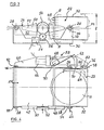
- FIG. 3 diagrammatically illustrates a record changer according to the invention
- a magazine 22 is provided for storing records R
- a loading/reproducing mechanism 24 is provided for receiving a selected record from the magazine 22 and reproducing information recorded thereon.
- the magazine 22 and the loading/reproducing mechanism 24 are both mounted for pivoting about two horizontal axes 26, 28, respectively, and are carried by a fixed frame 30. It is preferred that the magazine 22 be removable from the record changer, and, for this purpose, the magazine 22 is held in a open-ended box-like housing 32 having laterally-extending sleeves 34, 36 which are rotatably supported on vertical side members 38, 40 of the frame, allowing the magazine to pivot about the horizontal axis 26 which is also the axis of the sleeves 34, 36.
- the loading/reproducing mechanism 24 is carried by a movable frame or chassis 42 which is pivotally supported about the horizontal axis 28.
- the movable chassis 42 has laterally-extending sleeves 44, 46 rotatably supported on the opposite side members 38, 40 of the fixed frame 30.
- the magazine 22 is box-shaped and is supported for movement about its geometrical center and is thereby balanced about the supporting axis, while the movable chassis 42 carrying the loading/reproducing mechanism is supported about an axis 28 at the end of the chassis 42 remote from the magazine.
- the magazine 22 Since the magazine 22 is bulkier than the loading/reproducing mechanism 24, the support of the magazine at a geometrical center, by minimizing the extent of lateral movement of the magazine 22 as it swivels when shifted to locate a record compartement for transfer to the loading/reproducing mechanism, results in a record changer which has smaller overall height (1) than the height (L) of conventional record changers with the same capacity magazine, an important objective of the invention.
- both the magazine housing 32 and the movable chassis 42 for the loading/reproducing mechanism 24 have toothed members, herein shown as segments 48, 50, fastened thereto, the segments 48, 50 having gear teeth which mesh with a common drive gear 52 that moves both the magazine 22 and loading/reproducing mechanism 24 in a pivotal manner to produce coordinated angular displacements thereof about their respective axes 26, 28 between different fixed positions.
- the drive gear 52 is operated by a motor 54 through a reduction gear train 56.
- the magazine 22 and loading/reproducing mechanism 24 are movable between a series of fixed positions, and, in each fixed position, one of the compartments in the magazine 22 faces the loading/reproducing mechanism to permit a record to be transferred from the arrangement to the mechanism or vice versa.
- each compartment means is provided for storing a record in a storage plane Pl while in the loading/reproducing mechanism a support is provided for receiving a record in a loading plane P2.
- the pivotal displacements take place in opposite directions to align the storage plane Pl of a different one of the compartments with the loading plane P2 of the loading/reproducing mechanism at each of the fixed positions.
- a transfer mechanism 58 is mounted on the movable chassis 42 carrying the loading/reproducing mechanism being carried by a lateral extension 60 of the chassis 42.
- the transfer mechanism includes a lever member 62 which is pivotally mounted on the lateral extension 60 for movement from a position completely exterior to the magazine to a position penetrating a selected compartment within the magazine.
- Each compartment of the magazine preferably includes a locking lever 64.
- the transfer lever member 62 penetrates a selected compartment, it engages the locking lever 64 therein and causes the locking lever 64 to pivot and move a record within the compartment toward the loading position within the loading/reproducing mechanism 24.
- the locking lever 64 in each compartment is also provided to lock a record in the compartment upon reverse movement.
- the loading/reproducing mechanism 24 is preferably the type of mechanism disclosed in detail in U.S. Patent 4,513,409. This mechanism employs a support (not shown in Figure 4) which is rotatably mounted in the loading/reproducing mechanism 24 and travels in a helicoidal motion to transfer the record from the plane of the loading position to the parallel plane of the operating or playing position.
- the transfer lever member 62 is movable by a motor 66 which is connected to the transfer lever member 62 through a reduction gear drive 68 and a gear segment 70 which is fixed to the transfer lever member 62.
- the transfer lever member 62 is pivotally mounted on the lateral extension 60 of the movable chassis 42 and is rigidly fastened thereto so as to move with the movable chassis 42 as it pivots about its axis 28 (see Figure 4).
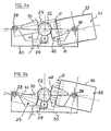
- an optical reading device 78 in the form of a diode-phototransistor adapted to detect optical information, which may be in the form of bars, depressions, reflecting area, etcetera, carried by the housing 32 of the magazine 22. These items of information correspond to the center of each compartment with the magazine and enable the loading/reproducing mechanism 24 and the transfer mechanism 58 to be very precisely aligned with the center of the compartment in which the record selected by the user is situated.
- the optical coding comprises an additional item of information 76, opposite the central compartment (the fifth compartment in the present case), this item of information 76 being detected by an optical reading device 78 similar to a device 80 for reading information 82 representing the positions of the individual compartments.
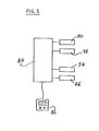
- the readout signal is then transmitted to a microprocessor 84 of the control system pictured in Figure 5, and this microprocessor retains, in one of its storage memories, the fact that the central compartment is opposite the loading/reproducing mechanism 24.
- compartment 1 may be the one situated at the top, as illustrated in Figure 3a
- compartment 10 may be the one at the bottom, as pictured in Figure 3b, facing the loading/reproducing mechanism 24.
- the microprocessor compares the number fed in with that stored and, depending on the result of this comparison, operates the motor 54 to rotate, clockwise or counterwise, depending on the sign of this comparison and the counting of the optical information and depending on the value of the difference obtained.
- the motor 54 positions the loading/reproducing mechanism 24 facing the compartment containing the selected record.
- the transfer mechanism motor 66 is then switched on by the program operating the microprocessor 84 and rotates the transfer lever member 62 which, by acting on the locking lever 64 within the compartment containing the selected record, transfers the record to the loading/reproducing mechanism 24.
- the record is then introduced into the loading/reproducing mechanism which is automatically operated to transfer the record onto a drive spindle where it may be clamped in operating position.
- the record is first disengaged from its drive means and brought to a position from which it may be transferred from the loading/reproducing mechanism and returned to its original compartment in the magazine 22.
- the axis of pivoting of the loading/reproducing mechanism 24 has advantageously been placed close to its opposite end from the magazine housing 32 and, therefore, the axis of the drive gear 52 is equidistant between the two axes 26, 28 of pivotal motion of the magazine 22 and the loading/reproducing mechanism 24.
- Any variation may be made to this geometry to take special conditions into account, and, of course, other connections achieving the same object may be used.
- gears connected by a rack which, given an alternating linear movement, would ensure the rotation of gears in opposite directions.
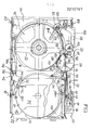
- the changer is shown in plan view in Figure 6, turned end-for-end from the plan view of Figure 4.
- Figure 7 is a side view of the changer as pictured in Figure 6, and Figure 8 is a plan view arranged similarly to Figure 6.
- the records are in the magazine, while in Figure 8 a record is shown in playing position in the loading/reproducing mechanism 24 after it has been transferred from a selected compartment.
- the loading/reproducing mechanism 24 is in the form of a rotationally- mounted support 95 receiving a record and performing a helical movement to raise and lower the record from a loading plane to a parallel operating or playback plane, as described in U.S. Patent 4,513,409.
- a peripheral segment 102 of the rotationally mounted support 95 is engaged with a gear 103 freely mounted on the movable chassis 42 and driven by a toothed rack 105 which is longitudinally moved by means of a first actuating slide 106 for the loading/reproducing mechanism 24.
- the other end 107 of the first actuating slide 106 carries a pin 108 associated with a profile 109 cut in a control cam 110.
- This control cam 110 is rotatable and is supported on the movable chassis 42 which carries the loading/reproducing mechanism 24, the control cam 110 being driven under the direction of the control system to rotate the loading/reproducing mechanism support 95 and cause it to travel in a helicoidal path to shift the position of the record between the loading and playing positions.
- This same control cam 110 is provided with a second profile 109' which is associated with a second actuating slide 112 for the record transfer mechanism 58, and the control cam 110 moves the second actuating slide 112 by means of a pin 111.
- the record transfer actuating slide 112 at the end adjacent the magazine has a toothed segment 113.
- a lateral extension 60 of the movable chassis 42 extends adjacent the magazine housing 32 and supports the second actuating slide 112 and a gear 114 which is engaged by the toothed segment 113 on the slide 112.
- the gear 114 carries a transfer lever arm 115 of the transfer mechanism 58 intended to work jointly with levers 100 contained in the compartments of the magazine 22 and which serve both to transfer a record when actuated to pivot in one direction, or to lock the record in the respective compartment when released to pivot in the reverse direction under the force of the spring 100'.
- the control cam 110 is rotated by a control motor 120 through reduction gear unit 122.
- This same control motor 120 rotates a transfert assist roller 130 located at the edge of the loading/reproducing mechanism support 95 for engagement with the periphery of a record upon its transfer into or out of the loading/reproducing mechanism, the roller 130 being operated through a gear and belt drive 138.
- This type of roller assist means is disclosed in detail in U.S. Patent Application Serial Number 768,562, filed August 23, 1985.
- the record transfer actuating slide 112 also includes a pin 140 mounted to engage an interlock lever 142 acted upon by a spring 143.
- This interlock lever 142 is provided with a pointed end 144 intended to penetrate into openings 145 cut in the edge of the magazine 22 in order to interlock the magazine 22 and the loading/reproducing mechanism 24 during the transfer and playback of a record.
- control cam 110 is rotated and, through the shape of the first and second profiles 109 and 109' cut therein, simultaneously ensures the displacement to the left of the record transfer actuating slide 112 and the clockwise rotation of the transfer roller 130.
- the pin 140 Upon such displacement, the pin 140 releases the interlock lever 142 so that, under the action of the spring 143, the pointed end 144 of the interlock lever 142 enters into the opening 145 corresponding to the magazine compartment facing the loading/reproducing mechanism 24 at the particular intermediate location in which it is positioned by the control system. Consequently, the motor 54 for positioning the magazine 22 with respect to the loading/reproducing mechanism 24 may be deenergized.
- the toothed segment 113 engages with the gear 114 and the lever arm of the transfer mechanism and through clockwise swiveling penetrates the selected compartment and acts on the locking lever 100 within the compartment facing the loading/reproducing mechanism.
- each of the parallel compartments of the magazine means are provided for storing a record in a storage plane Pl, preferably a V-shaped support that carries the record solely at its periphery and guides it by such engagement, as disclosed in U.S. Patent 4,510,591.
- the record which is stored therein is then moved toward the loading/reproducing mechanism.
- the record periphery comes into contact with the transfer roller 130, the contour of which imposes a rolling movement to the disc in association with a guiding face 150 on the loading/reproducing mechanism.
- the transfer roller 130 is mounted on a lever 160 and is acted on by a spring 162 to assist in the loading and unloading of the record on the support 95.
- the first profile 109 of the control cam 110 actuates the displacement to the left of the loading/reproducing mechanism actuating slide 106 and the positioning gear 105 rotates the record support 95 which moves helicoidally and, by lowering, positions the record on its driving and playback means. It is held in place by a clamping device, preferably of the type described in U.S. Patent 4,570,194.
- control motor 120 When it is desired to return the record to its storage compartment in the magazine, the control motor 120 is switched on but with reversed polarity to make it turn in the reverse direction.
- the loading/reproducing mechanism actuating slide 106 is first moved to the right, causing, through the gear 103 and teeth 102 on the support 95, the record support 95 to be rotated and moved in a helicoidal path, raising the record from its operating plane in the loading/reproducing mechanism, while a lever 118 mounted on the intermediate support drive gear 103 is moved pivotally into engagement with the record to start its ejection.
- the roller 130 rolls the disc in the other direction to lead it towards the compartment of the magazine to which it is being returned.
- the transfer actuating slide 112 is then moved to the right and the record is brought back into storage position within the compartment.
- the illustrated control circuit in Figure 5 controls power consumption of the motors 120, 58, ensuring, respectively, the transfer of a record and the positioning of the loading/reproducing mechanism and the magazine, and switches the unit to "stand-by"condition in case of over-consumption to avoid damage.
- the changer although switched on, will not respond to control if a spring-biased lever 182 retaining the magazine is not in proper position or if the door 184 is not properly closed ( Figure 7).
Landscapes
- Automatic Disk Changers (AREA)
Priority Applications (1)
| Application Number | Priority Date | Filing Date | Title |
|---|---|---|---|
| AT86870125T ATE61146T1 (de) | 1985-09-12 | 1986-09-10 | Schwenkbarer plattenwechsler. |
Applications Claiming Priority (4)
| Application Number | Priority Date | Filing Date | Title |
|---|---|---|---|
| BE0/215574A BE903223A (fr) | 1985-09-12 | 1985-09-12 | Appareil pour la reproduction et/ou l'enregistrement successif et/ou selectif de supports d'informations |
| BE215574 | 1985-09-12 | ||
| BE0/216659A BE904766R (fr) | 1985-09-12 | 1986-05-14 | Appareil pour la reproduction et/ou l'enregistrement successif et/ou selectif de supports d'informations. |
| BE216659 | 1986-05-14 |
Publications (3)
| Publication Number | Publication Date |
|---|---|
| EP0215767A2 true EP0215767A2 (de) | 1987-03-25 |
| EP0215767A3 EP0215767A3 (en) | 1988-01-20 |
| EP0215767B1 EP0215767B1 (de) | 1991-02-27 |
Family
ID=25654710
Family Applications (1)
| Application Number | Title | Priority Date | Filing Date |
|---|---|---|---|
| EP86870125A Expired - Lifetime EP0215767B1 (de) | 1985-09-12 | 1986-09-10 | Schwenkbarer Plattenwechsler |
Country Status (7)
| Country | Link |
|---|---|
| US (1) | US4701899A (de) |
| EP (1) | EP0215767B1 (de) |
| JP (1) | JPH0758577B2 (de) |
| KR (1) | KR870003489A (de) |
| BE (1) | BE904766R (de) |
| DE (1) | DE3677680D1 (de) |
| ES (1) | ES2005823A6 (de) |
Cited By (5)
| Publication number | Priority date | Publication date | Assignee | Title |
|---|---|---|---|---|
| JPS63164841U (de) * | 1987-04-17 | 1988-10-27 | ||
| EP0493034A1 (de) * | 1990-12-22 | 1992-07-01 | Sony Corporation | Plattenspieler |
| EP0519655A3 (en) * | 1991-06-20 | 1993-04-07 | Matsushita Electric Industrial Co., Ltd | Disk changer |
| EP0905686A3 (de) * | 1997-09-24 | 1999-07-07 | Victor Company of Japan, Ltd. | Verbesserte Aufbewahrungsstruktur für Speichermedium |
| EP1120786A1 (de) * | 2000-01-26 | 2001-08-01 | Hewlett-Packard Company, A Delaware Corporation | Technik zur Beseitigung der Totraumsendstellung in einem automatischen Medienwechsler |
Families Citing this family (27)
| Publication number | Priority date | Publication date | Assignee | Title |
|---|---|---|---|---|
| US4833552A (en) * | 1986-04-25 | 1989-05-23 | Staar, S.A. | Top loading record changer mechanism with removable magazine supported for swiveling between a top loading position and an operating position angularly displaced therefrom |
| JPS63273264A (ja) * | 1987-04-30 | 1988-11-10 | Nippon Columbia Co Ltd | 記録体の検索装置 |
| BE1001696A4 (fr) * | 1988-01-13 | 1990-02-13 | Staar Sa | Changeur pour supports d'enregistrements. |
| JPH01170358U (de) * | 1988-05-18 | 1989-12-01 | ||
| US5107475A (en) * | 1989-01-31 | 1992-04-21 | Pioneer Electronic Corporation | Automatic disk changer with a tray transfer device |
| US5041929A (en) * | 1989-09-29 | 1991-08-20 | Storage Technology Corporation | Autoloader for magnetic tape cartridges |
| US5153862A (en) * | 1989-11-06 | 1992-10-06 | North American Philips Corporation | Cassette for storing, moving and loading optical storage disk cartridges |
| US5274619A (en) * | 1990-09-04 | 1993-12-28 | Alpine Electronics, Inc. | Disk player with disk select function |
| US5297126A (en) * | 1990-09-12 | 1994-03-22 | Alpine Electronics, Inc. | Compact disk player with a mechanism for ejecting a selected disk |
| JP2645959B2 (ja) * | 1992-04-24 | 1997-08-25 | タナシン電機株式会社 | ディスク再生装置 |
| KR960011292B1 (ko) * | 1994-02-18 | 1996-08-21 | 현대전자산업 주식회사 | 정보기록매체의 자동 교환방법 및 그 장치 |
| US6178153B1 (en) | 1994-02-18 | 2001-01-23 | Hyundai Electronics Ind. Co., Ltd. | Compact disk auto-exchanger and method thereof |
| US5781523A (en) * | 1995-04-05 | 1998-07-14 | Hitachi, Ltd. | Disk reproducing apparatus capable of taking multi-inclined postures |
| JP3424438B2 (ja) * | 1996-02-20 | 2003-07-07 | ティアック株式会社 | 記録媒体再生装置 |
| US6081486A (en) * | 1996-06-06 | 2000-06-27 | Teac Corporation | Disk drive having a disk loading mechanism |
| JP3315034B2 (ja) * | 1996-06-07 | 2002-08-19 | ティアック株式会社 | 記録媒体再生装置 |
| JPH10199093A (ja) * | 1996-12-27 | 1998-07-31 | Nakamichi Corp | チェンジャ−型ディスク再生装置 |
| AU6140398A (en) * | 1997-02-07 | 1998-08-26 | Multidisc Technologies, Inc. | Compact disc storage and loader system |
| US5912873A (en) * | 1997-06-18 | 1999-06-15 | Multidisc Technologies | Compact disc transporter with dual transport sites |
| US5886974A (en) * | 1997-06-18 | 1999-03-23 | Multidisc Technologies | Compact disc loader and transport apparatus |
| JP3264866B2 (ja) * | 1997-07-02 | 2002-03-11 | 富士通株式会社 | ライブラリ装置用カートリッジ移送ロボット |
| US6234346B1 (en) * | 1997-07-11 | 2001-05-22 | Newco Enterprises, Inc. | Snack dispenser |
| US5886960A (en) * | 1997-11-04 | 1999-03-23 | Multidisc Technologies | Optical disc system using multiple optical heads for accessing information data |
| JP3754621B2 (ja) * | 2001-02-16 | 2006-03-15 | 日本電産ピジョン株式会社 | カム構造 |
| US20050169125A1 (en) * | 2003-05-30 | 2005-08-04 | Fujitsu Limited | Optical information storage apparatus and optical information storage system |
| JP2005310212A (ja) * | 2004-04-16 | 2005-11-04 | Mitsubishi Electric Corp | ディスク装置 |
| JP2012009120A (ja) * | 2010-05-28 | 2012-01-12 | Sony Corp | ディスクチェンジャー |
Family Cites Families (12)
| Publication number | Priority date | Publication date | Assignee | Title |
|---|---|---|---|---|
| US3272307A (en) * | 1966-09-13 | Conveyor system | ||
| US2839305A (en) * | 1951-05-31 | 1958-06-17 | Fidelitone Inc | Selective record changer |
| US2850285A (en) * | 1955-05-09 | 1958-09-02 | Ami Ind Inc | True sequence selector |
| US3085805A (en) * | 1957-09-18 | 1963-04-16 | Record Automaten A G | Record changing mechanism |
| US4016969A (en) * | 1975-07-22 | 1977-04-12 | Ppg Industries, Inc. | Flow dividing mechanism for a conveyor system |
| CH621305A5 (de) * | 1978-06-05 | 1981-01-30 | Sapal Plieuses Automatiques | |
| US4453188A (en) * | 1981-04-10 | 1984-06-05 | Amlyn Corporation | Disk drive |
| BE891428A (fr) * | 1981-12-10 | 1982-03-31 | Staar Sa | Dispositif de positionnement automatique du disque a jouer dans un appareil de reproduction. |
| BE891649A (fr) * | 1981-12-29 | 1982-04-16 | Staar Sa | Dispositif de positionnement et de verrouillage pour disques porteurs d'informations. |
| BE892073A (fr) * | 1982-02-09 | 1982-05-27 | Staar Sa | Dispositif de maintien d'un verrou magnetique pour tourne disque |
| US4635150A (en) * | 1982-02-22 | 1987-01-06 | Victor Company Of Japan Ltd. | Apparatus for automatically selecting and reproducing a recording medium |
| JPH0821188B2 (ja) * | 1983-12-27 | 1996-03-04 | 株式会社東芝 | ディスクオートチェンジャー装置 |
-
1986
- 1986-05-14 BE BE0/216659A patent/BE904766R/fr not_active IP Right Cessation
- 1986-08-27 US US06/900,890 patent/US4701899A/en not_active Expired - Lifetime
- 1986-09-09 JP JP61210831A patent/JPH0758577B2/ja not_active Expired - Fee Related
- 1986-09-10 DE DE8686870125T patent/DE3677680D1/de not_active Expired - Fee Related
- 1986-09-10 ES ES8601757A patent/ES2005823A6/es not_active Expired
- 1986-09-10 EP EP86870125A patent/EP0215767B1/de not_active Expired - Lifetime
- 1986-09-12 KR KR1019860007683A patent/KR870003489A/ko not_active Withdrawn
Cited By (8)
| Publication number | Priority date | Publication date | Assignee | Title |
|---|---|---|---|---|
| JPS63164841U (de) * | 1987-04-17 | 1988-10-27 | ||
| EP0493034A1 (de) * | 1990-12-22 | 1992-07-01 | Sony Corporation | Plattenspieler |
| US5956300A (en) * | 1990-12-22 | 1999-09-21 | Sony Corporation | Compact audio disc changer with disc drive mounted on movable elevator |
| EP0519655A3 (en) * | 1991-06-20 | 1993-04-07 | Matsushita Electric Industrial Co., Ltd | Disk changer |
| US5396475A (en) * | 1991-06-20 | 1995-03-07 | Matsushita Electric Industrial Co., Ltd. | Disk changer |
| EP0905686A3 (de) * | 1997-09-24 | 1999-07-07 | Victor Company of Japan, Ltd. | Verbesserte Aufbewahrungsstruktur für Speichermedium |
| EP1120786A1 (de) * | 2000-01-26 | 2001-08-01 | Hewlett-Packard Company, A Delaware Corporation | Technik zur Beseitigung der Totraumsendstellung in einem automatischen Medienwechsler |
| US6445652B1 (en) | 2000-01-26 | 2002-09-03 | Hewlett-Packard Company | Technique for eliminating end-of-travel dead space in media autochangers |
Also Published As
| Publication number | Publication date |
|---|---|
| BE904766R (fr) | 1986-09-01 |
| EP0215767B1 (de) | 1991-02-27 |
| JPH0758577B2 (ja) | 1995-06-21 |
| DE3677680D1 (de) | 1991-04-04 |
| ES2005823A6 (es) | 1989-04-01 |
| EP0215767A3 (en) | 1988-01-20 |
| US4701899A (en) | 1987-10-20 |
| JPS62117164A (ja) | 1987-05-28 |
| KR870003489A (ko) | 1987-04-17 |
Similar Documents
| Publication | Publication Date | Title |
|---|---|---|
| EP0215767B1 (de) | Schwenkbarer Plattenwechsler | |
| US4561078A (en) | Disc changer and disc holder and box for use with such a changer | |
| EP0351470B1 (de) | Automatische Plattenaustauschvorrichtung | |
| US4937690A (en) | Automatic exchanging system for storage and retrieval of magnetic tape cassettes | |
| EP0623924B1 (de) | Magazin-Schublade-Manipulationssystem für Datenträgerladevorrichtung | |
| JP3208787B2 (ja) | カセット移送装置 | |
| KR920007325B1 (ko) | 디스크 기억장치 | |
| US4949328A (en) | Disk player for playing both sides of a disk or multiple disks without ejection thereof and a disk player with a disk being played that overlaps disks stored in a storage receptor | |
| US4879615A (en) | Cartridge transfer mechanism for a disk file apparatus | |
| EP0317370B1 (de) | Kassettenladegerät für Digital-Audio-Bandaufzeichnungsgerät | |
| US6166877A (en) | Cassette auto changer system including tape signal reading means and selection means for selecting between a plurality of cassettes | |
| US5528567A (en) | Disk changer for optical disks having different sizes | |
| JP2644446B2 (ja) | データキャリヤローダ | |
| JPH0991831A (ja) | ディスクオートチェンジャー | |
| CA1150405A (en) | Cassette changer apparatus | |
| EP0389199B1 (de) | Automatisches Kassettenbandaufnahme- und -wiedergabegerät | |
| EP0526215B1 (de) | Ladegerät für Bandkassette und Platte | |
| US4984228A (en) | Dual drive changer for records | |
| EP0845777B1 (de) | Plattenladevorrichtung | |
| US5870358A (en) | Disk recording/reproducing apparatus having magazine for accommodating a plurality of disks and a tray position changing mechanism | |
| CA1276566C (en) | Swinging record changer | |
| US5715229A (en) | Disk recording/reproducing apparatus having two trays so that a disk in a magazine can be replaced by one tray when a disk in the other tray is being recorded/reproduced | |
| JPH0636269B2 (ja) | デイスクフアイル装置 | |
| EP0539665A1 (de) | Bandladegerät | |
| JPH0991934A (ja) | ディスクオートチェンジャー |
Legal Events
| Date | Code | Title | Description |
|---|---|---|---|
| PUAI | Public reference made under article 153(3) epc to a published international application that has entered the european phase |
Free format text: ORIGINAL CODE: 0009012 |
|
| AK | Designated contracting states |
Kind code of ref document: A2 Designated state(s): AT CH DE FR GB IT LI NL SE |
|
| PUAL | Search report despatched |
Free format text: ORIGINAL CODE: 0009013 |
|
| AK | Designated contracting states |
Kind code of ref document: A3 Designated state(s): AT CH DE FR GB IT LI NL SE |
|
| 17P | Request for examination filed |
Effective date: 19880211 |
|
| RAP3 | Party data changed (applicant data changed or rights of an application transferred) |
Owner name: STAAR SOCIETE ANONYME |
|
| 17Q | First examination report despatched |
Effective date: 19891116 |
|
| GRAA | (expected) grant |
Free format text: ORIGINAL CODE: 0009210 |
|
| AK | Designated contracting states |
Kind code of ref document: B1 Designated state(s): AT CH DE FR GB IT LI NL SE |
|
| PG25 | Lapsed in a contracting state [announced via postgrant information from national office to epo] |
Ref country code: SE Effective date: 19910227 Ref country code: AT Effective date: 19910227 |
|
| REF | Corresponds to: |
Ref document number: 61146 Country of ref document: AT Date of ref document: 19910315 Kind code of ref document: T |
|
| ITF | It: translation for a ep patent filed | ||
| REF | Corresponds to: |
Ref document number: 3677680 Country of ref document: DE Date of ref document: 19910404 |
|
| ET | Fr: translation filed | ||
| PLBE | No opposition filed within time limit |
Free format text: ORIGINAL CODE: 0009261 |
|
| 26N | No opposition filed | ||
| PGFP | Annual fee paid to national office [announced via postgrant information from national office to epo] |
Ref country code: CH Payment date: 19960815 Year of fee payment: 11 |
|
| PGFP | Annual fee paid to national office [announced via postgrant information from national office to epo] |
Ref country code: NL Payment date: 19960930 Year of fee payment: 11 |
|
| PG25 | Lapsed in a contracting state [announced via postgrant information from national office to epo] |
Ref country code: LI Free format text: LAPSE BECAUSE OF NON-PAYMENT OF DUE FEES Effective date: 19970930 Ref country code: CH Free format text: LAPSE BECAUSE OF NON-PAYMENT OF DUE FEES Effective date: 19970930 |
|
| PG25 | Lapsed in a contracting state [announced via postgrant information from national office to epo] |
Ref country code: NL Free format text: LAPSE BECAUSE OF NON-PAYMENT OF DUE FEES Effective date: 19980401 |
|
| REG | Reference to a national code |
Ref country code: CH Ref legal event code: PL |
|
| NLV4 | Nl: lapsed or anulled due to non-payment of the annual fee |
Effective date: 19980401 |
|
| REG | Reference to a national code |
Ref country code: GB Ref legal event code: 746 Effective date: 19990816 |
|
| REG | Reference to a national code |
Ref country code: GB Ref legal event code: IF02 |
|
| PGFP | Annual fee paid to national office [announced via postgrant information from national office to epo] |
Ref country code: DE Payment date: 20020919 Year of fee payment: 17 |
|
| PGFP | Annual fee paid to national office [announced via postgrant information from national office to epo] |
Ref country code: GB Payment date: 20030916 Year of fee payment: 18 |
|
| PGFP | Annual fee paid to national office [announced via postgrant information from national office to epo] |
Ref country code: FR Payment date: 20030917 Year of fee payment: 18 |
|
| PG25 | Lapsed in a contracting state [announced via postgrant information from national office to epo] |
Ref country code: DE Free format text: LAPSE BECAUSE OF NON-PAYMENT OF DUE FEES Effective date: 20040401 |
|
| PG25 | Lapsed in a contracting state [announced via postgrant information from national office to epo] |
Ref country code: GB Free format text: LAPSE BECAUSE OF NON-PAYMENT OF DUE FEES Effective date: 20040910 |
|
| GBPC | Gb: european patent ceased through non-payment of renewal fee |
Effective date: 20040910 |
|
| PG25 | Lapsed in a contracting state [announced via postgrant information from national office to epo] |
Ref country code: FR Free format text: LAPSE BECAUSE OF NON-PAYMENT OF DUE FEES Effective date: 20050531 |
|
| REG | Reference to a national code |
Ref country code: FR Ref legal event code: ST |
|
| PG25 | Lapsed in a contracting state [announced via postgrant information from national office to epo] |
Ref country code: IT Free format text: LAPSE BECAUSE OF NON-PAYMENT OF DUE FEES;WARNING: LAPSES OF ITALIAN PATENTS WITH EFFECTIVE DATE BEFORE 2007 MAY HAVE OCCURRED AT ANY TIME BEFORE 2007. THE CORRECT EFFECTIVE DATE MAY BE DIFFERENT FROM THE ONE RECORDED. Effective date: 20050910 |