EP0215827B1 - Schaltung zur steuerung eines bürstenlosen elektromotors - Google Patents
Schaltung zur steuerung eines bürstenlosen elektromotors Download PDFInfo
- Publication number
- EP0215827B1 EP0215827B1 EP86901384A EP86901384A EP0215827B1 EP 0215827 B1 EP0215827 B1 EP 0215827B1 EP 86901384 A EP86901384 A EP 86901384A EP 86901384 A EP86901384 A EP 86901384A EP 0215827 B1 EP0215827 B1 EP 0215827B1
- Authority
- EP
- European Patent Office
- Prior art keywords
- polarity
- winding
- control
- voltage
- windings
- Prior art date
- Legal status (The legal status is an assumption and is not a legal conclusion. Google has not performed a legal analysis and makes no representation as to the accuracy of the status listed.)
- Expired
Links
- 238000004804 winding Methods 0.000 claims abstract description 42
- 238000005406 washing Methods 0.000 claims abstract description 9
- 238000009966 trimming Methods 0.000 abstract 3
- 230000001360 synchronised effect Effects 0.000 description 3
- 238000011161 development Methods 0.000 description 2
- 230000018109 developmental process Effects 0.000 description 2
- 238000009987 spinning Methods 0.000 description 2
- 230000002159 abnormal effect Effects 0.000 description 1
- 230000000694 effects Effects 0.000 description 1
- 230000007257 malfunction Effects 0.000 description 1
- 238000000034 method Methods 0.000 description 1
Images

Classifications
-
- H—ELECTRICITY
- H02—GENERATION; CONVERSION OR DISTRIBUTION OF ELECTRIC POWER
- H02K—DYNAMO-ELECTRIC MACHINES
- H02K29/00—Motors or generators having non-mechanical commutating devices, e.g. discharge tubes or semiconductor devices
- H02K29/06—Motors or generators having non-mechanical commutating devices, e.g. discharge tubes or semiconductor devices with position sensing devices
-
- H—ELECTRICITY
- H02—GENERATION; CONVERSION OR DISTRIBUTION OF ELECTRIC POWER
- H02P—CONTROL OR REGULATION OF ELECTRIC MOTORS, ELECTRIC GENERATORS OR DYNAMO-ELECTRIC CONVERTERS; CONTROLLING TRANSFORMERS, REACTORS OR CHOKE COILS
- H02P6/00—Arrangements for controlling synchronous motors or other dynamo-electric motors using electronic commutation dependent on the rotor position; Electronic commutators therefor
- H02P6/08—Arrangements for controlling the speed or torque of a single motor
-
- H—ELECTRICITY
- H02—GENERATION; CONVERSION OR DISTRIBUTION OF ELECTRIC POWER
- H02P—CONTROL OR REGULATION OF ELECTRIC MOTORS, ELECTRIC GENERATORS OR DYNAMO-ELECTRIC CONVERTERS; CONTROLLING TRANSFORMERS, REACTORS OR CHOKE COILS
- H02P6/00—Arrangements for controlling synchronous motors or other dynamo-electric motors using electronic commutation dependent on the rotor position; Electronic commutators therefor
- H02P6/24—Arrangements for stopping
Definitions
- the invention relates to a circuit for controlling a brushless electric motor, in particular a slow-running flat motor, the z. B. is suitable for the direct drive of washing machines.
- a direct drive of the washing drum of a washing machine the speed of rotation must be changed within wide limits, namely 40-70 rpm for the washing process and about 1,000 rpm for the spinning process. This is no longer possible with synchronous motors because the speed of a synchronous motor depends on the frequency that cannot be influenced.
- the invention has for its object to provide a circuit for controlling a brushless electric motor, which enables the motor to run slowly regardless of the mains frequency.
- the problem of additionally maintaining the symmetrical load on the network is maintained despite an asymmetrical supply to the stator winding.
- a motor with the control circuit has several advantages. Due to the speed of the motor, which can be influenced within wide limits, this can, for. B. can be used in a washing machine for direct drive of the drum both in the slow washing process and in the fast spinning process. By controlling the currents supplied to the stator windings and the brushless rotor, no collectors are necessary, which increases reliability. Switching the direction of rotation, which is particularly important in washing machines, can be achieved purely electronically by controlling the stator winding, so that no reading relay is required. Electrical braking can also be achieved by means of an electronic control. For this purpose, e.g. B.
- phase cut control also allows a change in the torque because the electrical energy supplied to the motor and thus the torque generated can be influenced by changing the phase cut angle.
- the application of the control circuit according to claim 1 and the division of the stator winding according to claim 2 are preferably carried out with any existing stator winding. However, it is also possible to limit this application to only one stator winding. This is particularly possible at a high speed at which the frequency of the magnetic field and the mains frequency are approximately the same.
- the motor can then run similarly to a synchronous motor, in which the torque generated can be adjusted by changing the phase angle.
- the line voltage can be directly the voltage taken from a network. But you can also with a voltage converter (inverter) from a DC voltage, for. B. a battery can be derived if the engine power is less and a supply with a battery enables.
- the torque generated by the motor is usually not constant, but changes periodically via the angle of rotation of the motor. However, this torque is sufficiently integrated by the inertia of the rotor and the parts driven by it.
- the rotor 1 shows the rotor 1 of a drive motor, two stator windings S1, S2 and two Hall elements D1, D2.
- the rotor 1 has a north pole N and a south pole S diametrically opposite, which are formed by permanent magnets.
- the Hall elements D1 and D2 generate voltages eH1 and eH2, which indicate the respective angular position of the rotor 1.
- the voltages eH1 and eH2 control the currents iS1, iS2 supplied to the windings S1, S2 in such a way that the windings S1, S2 alternately generate north poles and south poles. These interact with the poles of the stator 1 and cause the rotor 1 to rotate in the desired direction.
- FIG. 2 shows the course of the voltages and currents shown in FIG. 1.
- the currents iS1 and iS2 are mutually shifted in phase by 90 ° according to the position of the windings S1, S2.
- the north and south poles generated by the windings S1, S2 thus form the rotating field required for the rotation of the rotor 1. If the currents iS1, iS2 immediately from the Line frequency are derived, the speed of the motor is determined by the line frequency and could only be changed in stages by changing the number of poles, i.e. the required stator windings.
- Fig. 3 shows an embodiment in which the speed is not determined by the frequency of the applied mains voltage UN.
- the mains voltage UN is applied to the two windings S1, S2 via two triacs T1, T2.
- Triacs form switches that conduct an alternating current in both directions and can be switched on and off as required at a control electrode, the so-called gate.
- the triacs T1, T2 are controlled by the control circuit 2.
- the mains voltage UN and, on the other hand, the two voltages eH1 eH2 from the Hall elements D1, D2 are applied to the control circuit 2.
- Fig. 4 shows that the frequency of the voltage eH1 is significantly lower than the frequency of the mains voltage UN.
- a control voltage for the triac T1 is generated from the voltages eH1 and UN, which only briefly controls it in the sense of a leading edge control only during the periods ⁇ t.
- the periods .DELTA.t each start at the maximum of the positive half-wave of the mains voltage UN.
- the winding S1 thus receives voltage pulses VS1 of the same polarity, which generate essentially proportional current pulses iS1 in the winding S1. These current pulses of constant polarity z.
- the frequency of the voltage eH1 and thus the duration t1 to t2 is not predetermined by the network frequency, but can be selected independently of the network frequency.
- the time t1 to t2 can thus be of any length compared to the network period, so that a low speed which is independent of the network frequency is achieved.
- the voltage eH1 starts from period t2, the voltage eH1 generates ignition pulses with a different phase position for its triac T1 due to its negative half-wave, so that voltage pulses VS1 and thus corresponding current pulses iS1 are now generated from the negative half-waves of the mains voltage UN.
- the magnetic pole generated by the winding S1 is reversed.
- Each group of voltage and current pulses during the time t1 to t2 thus corresponds to a half-wave of the curve iS1 in FIG. 2.
- the winding S1 consisting of S1a and S1 is fed with current pulses of the same polarity in each case during the half-life of the voltage eH1 in the effect on the magnetic field.
- the triac T11 is controlled by the applied control voltage only during the positive current pulses in accordance with the current flow angle of the phase control and the triac T12 only during the duration of the negative current pulses iN1.
- the total winding S1 from t1 to t2 is fed with asymmetrical current pulses of constant polarity according to FIG. 6c, so that a specific magnetic pole, N or S, is generated becomes.
- a polarity reversal takes place, as in FIG. 4, so that now the negative current pulses iN1 reach the winding S1 a and the positive current pulses iN1 reach the partial winding S1, so that at time t2 the necessary pole change by Winding S1 generated magnetic pole occurs.
- the winding S2 can be operated in the same way. However, it is also possible to feed only one stator winding in the manner described.
Landscapes
- Engineering & Computer Science (AREA)
- Power Engineering (AREA)
- Control Of Ac Motors In General (AREA)
- Control Of Motors That Do Not Use Commutators (AREA)
Description
- Die Erfindung betrifft eine Schaltung zur Steuerung eines bürstenlosen Elektromotors, insbesondere eines langsam laufenden Flachmotors, der z. B. für den Direktantrieb von Waschmaschinen geeignet ist. Bei einem Direktantrieb der Waschtrommel einer Waschmaschine muß die Drehgeschwindigkeit in weiten Grenzen, nämlich 40-70 Upm für den Waschvorgang und etwa 1 000 Upm für den Schleudervorgang geändert werden. Mit synchronmotoren ist dieses ohneweiteres nicht möglich, weil die Drehzahl eines Synchronmotors von der nicht beinfiußbaren Netzfrequenz abhängig ist.
- Es ist bekannt (DE-OS 15 38 916, 15 38 893), die Statorwicklungen des mit einem permanentmagnetischen Rotor versehenen Motors über elektronisch steuerbare Schalter an das Netz anzuschließen und an die Steuerelektroden der Schalter eine Phasenanschnittsteuerung bewirkende aus der RotorsteHung abgeleitete Steuerspannungen anzulegen. Die Steuerspannungen werden dabei durch vom Rotor gesteuerte Hallgeneratoren gewonnen.
- Der Erfindung liegt die Aufgabe zugrunde, eine Schaltung zur Steuerung eines bürstenlosen Elektromotors zu schaffen, die unabhängig von der Netzfrequenz einen Langsamlauf des Motors ermöglicht. Durch eine-Weiteeldung der Erfindung wird zusätzlich die Aufgabe gelöst, däß trotz einer unsymmetrischen Speisung der Statorwicklung eine symmetrische Belastung des Netzes eingehalten wird.
- Diese Aufgaben werden durch die im Anspruch 1 bzw. Anspruch 2 beschriebene Erfindung gelöst. Vorteilhafte Weiterbildungen der Erfindung sind in den Unteransprüchen beschrieben.
- Der Betrieb eines Motors mit der erfindungsgemäßen Steuerschaltung hat mehrere Vorteile. Durch die in weiten Grenzen beeinflußbare Drehzahl des Motors kann dieser z. B. in einer Waschmaschine zum Direktantrieb der Trommel sowohl bei dem langsamen Waschvorgang als auch bei dem schnellen Schleudervorgang verwendet werden. Durch die Steuerung der den Statorwicklungen zugeführten Ströme und den bürstenlosen Rotor sind keine Kollektoren notwendig, wodurch die Zuverlässigkeit erhöht wird. Eine Umschaltung der Drehrichtung, die insbesondere bei Waschmaschinen wichtig ist, kann rein elektronisch durch die Steuerung der Statorwicklung erreicht werden, so daß kein Lestungsrelais erforderlich ist. Durch eine elektronische Steuerung kann außerdem eine elektrische Bremsung erreicht werden. Zu diesem Zweck wird z. B. durch Umpolung der zugeführten Spannungen ein Drehmoment erzeugt, das der gerade vorliegenden Drehrichtung entgegengesetzt gerichtet ist. Die Phasenschnittsteuerung erlaubt außerdem eine Änderung des Drehmomentes, weil durch ein Änderung des Phasenanschnittwinkels die dem Motor zugeführte elektrische Energie und damit das erzeugte Drehmoment beeinflußt werden können.
- Die Anwendung der Steuerschaltung gemäß Anspruch 1 und die Aufteilung der Statorwicklung gemäß Anspruch 2 erfolgen vorzugsweise bei jeder vorhandenen Statorwicklung. Es ist aber auch möglich, diese Anwendung auf nur eine Statorwicklung zu beschränken. Das ist insbesondere möglich bei einer hohen Geschwindigkeit, bei der die Frequenz des magnetischen Feldes und die Netzfrequenz etwa gleich sind. Dann kann der Motor ähnlich wie ein Synchronmotor laufen, bei dem das erzeugte Drehmoment durch Änderung des Phasenanschnittwinkels einstellbar ist. Die Netzspannung kann unmittelbar die einem Netz entnommene Spannung sein. Sie kann aber auch mit einem Spannungswandler (Wechselrichter) aus einer Gleichspannung, z. B. einem Akku, abgeleitet werden, wenn die Motorleistung kleiner ist und eine Speisung mit einem Akku ermöglicht. Das von Motor erzeugte Drehmoment ist in der Regel nicht konstant, sondern ändert sich periodisch über den Drehwinkel des Motors. Dieses Drehmoment wird jedoch durch die Trägheit des Rotors und der von diesem angetriebenen Teile ausreichend integriert.
- Die Erfindung wird in folgenden anhand der Zeichnung erläutert. Darin zeigen
- Fig. 1 das Grundprinzip der erfindungsgemäßen Steuerung,
- Fig. 2 Kurven zur Erläuterung der anordnung nach Fig. 1,
- Fig. 3 ein praktisches Ausführungsbeispiel der Erfindung,
- Fig. 4 Kurven zur Erläuterung der Wirkungsweise der Anordnung nach Fig. 3,
- Fig. 5 ein Ausführungsbeispiel für die Weiterbildung der Erfindung gemäß Anspruch 2 und
- Fig. 6 Kurven zur Erläuterung der Wirkungsweise der Anordnung nach Fig. 5.
- Fig. 1 zeigt von einem Antriebsmotor den Rotor 1, zwei Statorwicklungen S1, S2 und zwei Hall-Elemente D1, D2. Der Rotor 1 hat diametral gegenüber liegend einen Nordpol N sowie einen Südpol S, die durch Permanentmagnete gebildet sind. Die Hall-Elemente D1 und D2 erzeugen Spannungen eH1 und eH2, die die jeweiligen Winkelstellung des Rotors 1 anzeigen. Die Spannungen eH1 und eH2 steuern die den Wicklungen S1, S2 zugeführten Ströme iS1, iS2 derart, daß die Wicklungen S1, S2 abwechselnd Nordpole und Südpole erzeugen. Diese wirken mit den Polen des Stators 1 zusammen und verursachen die Rotation des Rotors 1 in der gewünschten Richtung.
- Fig. 2 zeigt den Verlauf der in Fig. 1 dargestellten Spannungen und Ströme. Die Ströme iS1 und iS2 sind gegeneinander um 90° in der Phase verschoben entsprechend der Lage der Wicklungen S1, S2. Die durch die Wicklungen S1, S2 erzeugten Nord- und Südpole bilden also das für die Rotation des Rotors 1 erforderliche Drehfeld. Wenn die Ströme iS1, iS2 unmittelbar aus der Netzfrequenz abgeleitet werden, ist die Drehzahl des Motors durch die Netzfrequenz vorgegeben und könnte nur durch eine Änderung der Polzahl, also der benötigten Statorwicklungen, in Stufen geändert werden.
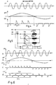
- Fig. 3 zeigt eine Ausbildung, bei der die Drehzahl nicht durch die Frequenz der angelegten Netzspannung UN festgelegt ist. Die Netzspannung UN ist über zwei Triacs T1, T2 an die beiden Wicklungen S1, S2 angelegt. Triacs bilden Schalter, die einen Wechselstrom in beiden Richtungen leiten und an einer Steuerelektrode, dem sogenannten Gate, beliebig ein- und ausschaltbar sind. Die Triacs T1, T2 werden von der Steuerschaltung 2 gesteuert. An die Steuerschaltung 2 sind einerseits die Netzspannung UN und andererseits die beiden Spannungen eH1 eH2 von den Hall-Elementen D1, D2 angelegt.
- Fig. 4 zeigt, daß die Frequenz der Spannung eH1 wesentlich geringer ist als die Frequenz der Netzspannung UN. Aus den Spannungen eH1 und UN wird eine Steuerspannung für den Triac T1 erzeugt, die diesen jeweils nur während der Zeiträume Δt kurzzeitig im Sinne einer Phasenanschnittsteuerung leitend steuert. Die Zeiträume Δt beginnen jeweils beim Maximum der positiven Halbwelle der Netzspannung UN. Die Wicklung S1 bekommt also Spannungsimpulse VS1 gleicher Polarität, die im wesentlichen proportionale Stromipulse iS1 in der Wicklung S1 erzeugen. Diese Stromipulse gleichbleibender Polarität erzeugen z. B. einen Nordpol. Dieser Vorgang erstreckt sich von t1 bis t2. Es ist ersichtilich, daß die Frequenz der Spannung eH1 und damit die Dauer t1 bis t2, nicht durch die Netzfrequenz vorgegeben ist, sondern unabhängig von der Netzfrequenz gewählt werden kann. Die Zeit t1 bis t2 kann also beliebig groß gegenüber der Netzperiode sein, so daß eine von der Netzfrequenz unabhängige, niedrige Drehzahl erreicht wird.
- Beginnend vom Zeitraum t2 erzeugt die Spannung eH1 durch ihre negative Halbwelle für den Triac T1 Zündimpulse mit einer anderen Phasenlage, so daß jetzt aus den negativen Halbwellen der Netzspannung UN Spannungsimpulse VS1 und damit entsprechende Stromimpulse iS1 erzeugt werden. Dadurch wird der von der Wicklung S1 erzeugte Magnetpol umgepolt. Jeweils die Gruppe von Spannungs- und Stromimpulsen während der Zeit t1 bis t2 entspricht also einer Halbwelle der Kurve iS1 in Fig. 2.
- Wie Fig. 4 zeigt, werden während eines längeren Zeitraumes, dort t1 bis t2, nur die positiven' Halbwellen der Netzspannung UN ausgewertet. Das bedeutet eine unsymmetrische, anomale Belastung des Netzes, die den Wirkungsgrad des Motors vermindert, gegen Vorschriften verstoßen und zu Störungen führen kann.
- Bei der Weiterbildung gemäß Fig. 5 wird dieser Nachteil der unsymmetrischen Belastung des Netzes vermieden. Durch entsprechende Steuerung der Triacs T11, T12 werden dem Netz Stromimpulse iN1 gemäß Fig. 6d entnommen. Das bedeutet, daß die positiven und negativen Halbwellen der Netzspannung UN gleichmäßig ausgewertet werden und somit eine symmetrische Belastung des Netzes vorliegt. Die Wicklung S1 ist in zwei Teilwicklungen S1a und S1b aufgeteilt, die einander gleich und magnetisch entgegengesetzt gepolt sind, wie durch die Punkte angedeutet. Durch entsprechende Steuerung der Triacs T11, T12 werden die positiven Stromimpulse iN1 der Teilwicklung S1a und die negativen Stromimpulse iN1 der Teilwicklung S1b zugeführt. Da die Wicklungen gegengesetzt gepolt sind, ergibt sich für die Summe der Spannung VS11 und VS12 und damit auch für den Strom iS1 für die Gesamtwicklung S1 = S1a + S1b die Kurvenform gemäß Fig. 6c. Wie in Fig. 4 wird also die aus S1a und S1 bestehende Wicklung S1 in der Auswirkung auf das magnetische Feld jeweils während der Halbdauer der Spannung eH1 mit Stromimpulsen gleicher Polarität gespeist. Der Triac T11 ist durch die angelegte Steuerspannung jeweils nur während der positiven Stromimpulse entsprechend dem Stromflußwinkel der Phasenanschnittsteuerung durchlässig gesteuert und der Triac T12 nur während der Dauer der negativen Stromimpulse iN1. Während also das Netz in erwünschter Weise durch den Strom iN1 eine symmetrische Belastung gemäß Fig. 6d erfährt, wird die Gesamtwicklung S1 von t1 bis t2 mit unsymmetrischen Stromimpulsen gleichbleibender Polarität gemäß Fig. 6c gespeist, so daß ein bestimmter Magnetpol, N oder S, erzeugt wird. In dem auf den Zeitpunkt t2 folgenden Zeitram erfolgt wie in Fig. 4 eine Umpolung, so daß nun die negativen Stromimpulse iN1 auf die Wicklung S1 a und die positiven Stromimpulse iN1 auf die Teilwicklung S1 gelangen, damit im Zeitpunkt t2 der notwendige Polwechsel des durch die Wicklung S1 erzeugten Magnetpols auftritt. Auf gleiche Weise kann mit der Wicklung S2 verfahren werden. Es ist aber auch möglich, nur eine Statorwicklung in der beschriebenen Weise zu speisen.
Claims (6)
Priority Applications (1)
| Application Number | Priority Date | Filing Date | Title |
|---|---|---|---|
| AT86901384T ATE47258T1 (de) | 1985-03-06 | 1986-02-15 | Schaltung zur steuerung eines buerstenlosen elektromotors. |
Applications Claiming Priority (2)
| Application Number | Priority Date | Filing Date | Title |
|---|---|---|---|
| DE3507883 | 1985-03-06 | ||
| DE19853507883 DE3507883A1 (de) | 1985-03-06 | 1985-03-06 | Schaltung zur steuerung eines buerstenlosen elektromotors |
Publications (2)
| Publication Number | Publication Date |
|---|---|
| EP0215827A1 EP0215827A1 (de) | 1987-04-01 |
| EP0215827B1 true EP0215827B1 (de) | 1989-10-11 |
Family
ID=6264337
Family Applications (1)
| Application Number | Title | Priority Date | Filing Date |
|---|---|---|---|
| EP86901384A Expired EP0215827B1 (de) | 1985-03-06 | 1986-02-15 | Schaltung zur steuerung eines bürstenlosen elektromotors |
Country Status (6)
| Country | Link |
|---|---|
| US (1) | US4780652A (de) |
| EP (1) | EP0215827B1 (de) |
| JP (1) | JPS62502163A (de) |
| AT (1) | ATE47258T1 (de) |
| DE (2) | DE3507883A1 (de) |
| WO (1) | WO1986005336A1 (de) |
Families Citing this family (17)
| Publication number | Priority date | Publication date | Assignee | Title |
|---|---|---|---|---|
| DE3841147A1 (de) * | 1988-12-07 | 1990-06-13 | Mulfingen Elektrobau Ebm | Verfahren zum ansteuern eines wechselstrom-motors sowie nach diesem verfahren ansteuerbarer wechselstrom-motor |
| US4942345A (en) * | 1989-02-14 | 1990-07-17 | Emerson Electric Co. | Pole changing switched reluctance motor and method |
| US5053688A (en) * | 1989-03-07 | 1991-10-01 | Sundstrand Corporation | Feedback circuit for eliminating DC offset in drive current of an AC motor |
| US5343129A (en) * | 1990-06-18 | 1994-08-30 | Papst Licensing Gmbh | Drive circuit for a brushless direct-current motor |
| DE4216837C2 (de) * | 1992-05-21 | 1995-11-16 | Daimler Benz Aerospace Ag | Radartarnung für langsamfliegende rollstabilisierte Flugkörper |
| FR2706226B1 (fr) * | 1993-05-05 | 1996-10-11 | Plumer Sa | Dispositif de commande de variation de puissance et/ou de vitesse d'une charge, tel que d'un moteur ou autre. |
| WO1995012240A1 (en) * | 1993-10-26 | 1995-05-04 | Chongqing Iron & Steel Designing Institute, Ministry Of Metallurgical Industry | Method and apparatus for controlling an ac high-frequency motor |
| IT1273149B (it) * | 1994-04-15 | 1997-07-04 | Merloni Elettrodomestici Spa | Macchina lavastoviglie perfezionata con un sistema elettronico di regolazione della pressione dell'acqua di lavaggio |
| US5675226A (en) * | 1995-09-06 | 1997-10-07 | C.E.Set. S.R.L. | Control circuit for an synchronous electric motor of the brushless type |
| JP3290354B2 (ja) * | 1996-07-05 | 2002-06-10 | 株式会社東芝 | 洗濯機及び洗濯機の駆動方法 |
| IT1289817B1 (it) * | 1996-12-30 | 1998-10-16 | Plaset Srl | Dispositivo per il controllo di un motore elettrico sincrono con rotore a magnete permanente |
| DE19701856A1 (de) * | 1997-01-21 | 1998-07-23 | Wunnibald Kunz | Elektronische Anlauf und Betriebssteuerung für einen Einphasen-Synchronmotor |
| ITTO980027A1 (it) * | 1998-01-15 | 1999-07-15 | Plaset Srl | Circuito di pilotaggio per un motore elettrico sincrono in corrente al ternata. |
| US6433505B2 (en) * | 1998-09-25 | 2002-08-13 | Michael Saman, Jr. | Phase shifting network |
| ES2197822B1 (es) * | 2002-06-18 | 2005-09-16 | Fagor, S. Coop. | Dispositivo electronico para el control de un motor sincrono con rotor de iman permanente. |
| DE50311997D1 (de) * | 2003-01-21 | 2009-11-19 | Grundfos As | Verfahren zum Steuern des Zündwinkels und einphasiger wechselstromversorgter Elektromotor |
| US10056852B2 (en) | 2016-01-22 | 2018-08-21 | Canarm Ltd. | Controller for EC motor and method thereof |
Family Cites Families (15)
| Publication number | Priority date | Publication date | Assignee | Title |
|---|---|---|---|---|
| US3333171A (en) * | 1964-11-17 | 1967-07-25 | Carrier Corp | Dynamoelectric machine including a particular pole face arcuate length and scr fed windings |
| DE1538893A1 (de) * | 1966-08-16 | 1970-04-23 | Licentia Gmbh | Buerstenloser Universalmotor |
| DE1538916A1 (de) * | 1966-10-24 | 1970-10-22 | Licentia Gmbh | Buerstenloser Universalmotor |
| US3466519A (en) * | 1966-10-24 | 1969-09-09 | Carrier Corp | Direct current motor employing a static switching arrangement |
| JPS4921488B1 (de) * | 1967-03-24 | 1974-06-01 | ||
| DE2002767A1 (de) * | 1970-01-16 | 1971-07-22 | Siemens Ag | Stromrichtermaschine fuer steuerbare Drehzahlen |
| JPS5420621B2 (de) * | 1972-06-24 | 1979-07-24 | ||
| US3908158A (en) * | 1973-05-09 | 1975-09-23 | Borg Warner | Control system for adjusting a-c motor speed at line frequency or a subharmonic of the line frequency |
| GB1480899A (en) * | 1973-10-19 | 1977-07-27 | Secr Defence | Phase shifting apparatus |
| DE2549157C3 (de) * | 1975-11-03 | 1982-03-18 | Electrostar Schöttle GmbH & Co, 7313 Reichenbach | Anordnung zur Steuerung der Drehzahl eines elektrischen Mehrphasen-Wechselstromsynchronmotors mit Permanentmagnet- oder Reluktanzrotor |
| US4238719A (en) * | 1978-03-24 | 1980-12-09 | Bourbeau Frank J | Rotatable transformer field excitation system for variable speed brushless synchronous motor |
| JPS56121377A (en) * | 1980-02-29 | 1981-09-24 | Jeol Ltd | Motor driving device |
| US4431958A (en) * | 1981-01-30 | 1984-02-14 | Eaton Corporation | Control apparatus for single phase AC induction motor |
| US4528485A (en) * | 1982-04-13 | 1985-07-09 | General Electric Company | Electronically commutated motor, method of operating such, control circuit, laundry machine and drive therefor |
| JPS60176473A (ja) * | 1984-02-23 | 1985-09-10 | Matsushita Electric Ind Co Ltd | 永久磁石回転子型同期電動機 |
-
1985
- 1985-03-06 DE DE19853507883 patent/DE3507883A1/de not_active Withdrawn
-
1986
- 1986-02-15 JP JP61501213A patent/JPS62502163A/ja active Pending
- 1986-02-15 AT AT86901384T patent/ATE47258T1/de not_active IP Right Cessation
- 1986-02-15 US US06/940,761 patent/US4780652A/en not_active Expired - Fee Related
- 1986-02-15 WO PCT/EP1986/000077 patent/WO1986005336A1/de not_active Ceased
- 1986-02-15 EP EP86901384A patent/EP0215827B1/de not_active Expired
- 1986-02-15 DE DE8686901384T patent/DE3666315D1/de not_active Expired
Also Published As
| Publication number | Publication date |
|---|---|
| US4780652A (en) | 1988-10-25 |
| DE3666315D1 (en) | 1989-11-16 |
| DE3507883A1 (de) | 1986-09-18 |
| JPS62502163A (ja) | 1987-08-20 |
| EP0215827A1 (de) | 1987-04-01 |
| WO1986005336A1 (fr) | 1986-09-12 |
| ATE47258T1 (de) | 1989-10-15 |
Similar Documents
| Publication | Publication Date | Title |
|---|---|---|
| DE69716086T2 (de) | Elektrische maschinen | |
| DE2827340C2 (de) | Antriebseinrichtung mit wenigstens zwei Elektromotoren | |
| WO1986005336A1 (fr) | Circuit de commande d'un moteur electrique sans brosses | |
| DE69727651T2 (de) | Vorrichtung zur Steuerung eines Synchronomotors mit einem Dauermagnetläufer | |
| DE3012833C2 (de) | ||
| EP0762625A1 (de) | Elektrischer Antrieb | |
| DE2305251A1 (de) | Asynchronmaschine zur erzeugung von wechsel- bzw. gleichspannungen | |
| DE102017126621A1 (de) | Motor und Motortreiberschaltung | |
| EP0221939B1 (de) | Schaltung zur steuerung eines bürstenlosen elektromotors | |
| DE1513389A1 (de) | Verfahren und Vorrichtung zur Drehzahlregelung von Mehrphasenmotoren | |
| EP0516807B1 (de) | Schaltungsanordnung zum betreiben eines mehrphasen-synchronmotors an einem gleichspannungsnetz | |
| EP0654890B1 (de) | Vorrichtung zum Antrieb eines Einphasen-Synchronmotors, insbesondere zum Antrieb eines Pumpenantriebes in einem Haushaltsgerät | |
| DE19722453C1 (de) | Elektrisches Antriebssystem | |
| EP3629468A1 (de) | Verfahren zum betreiben einer drehstrommaschine | |
| BE1030973B1 (de) | Antriebssystem | |
| DE3341948A1 (de) | Schaltung zur erzeugung eines zweiphasigen treiberstromes fuer einen bipolaren buerstenlosen motor | |
| DE2150262C3 (de) | Drehzahlsteuerung oder -regelung für einen aus einem Wechselstromnetz gleichstromgespeisten, elektrischen Motor mit einem dazu in Reihe geschalteten Heizwiderstand | |
| BE1029061B1 (de) | Verfahren zum Ansteuern eines mindestens zweiphasigen bürstenlosen Motors | |
| DE9407983U1 (de) | Vorrichtung zum Antrieb eines Einphasen-Synchronmotors, insbesondere zum Antrieb eines Pumpenantriebes in einem Haushaltsgerät | |
| DE1538893A1 (de) | Buerstenloser Universalmotor | |
| DE102020119357A1 (de) | Motorantrieb-Steuervorrichtung, Motoreinheit und Motorantrieb-Steuerverfahren | |
| DE3218740C2 (de) | ||
| EP4593281A1 (de) | Antriebssystem | |
| DE3348465C2 (de) | Steueranordnung für einen elektronisch kommutierten Gleichstrommotor | |
| EP0574010A2 (de) | Elektronisch kommutierter Motor, gesteuert mit Gleichstromimpulsen |
Legal Events
| Date | Code | Title | Description |
|---|---|---|---|
| PUAI | Public reference made under article 153(3) epc to a published international application that has entered the european phase |
Free format text: ORIGINAL CODE: 0009012 |
|
| 17P | Request for examination filed |
Effective date: 19861008 |
|
| AK | Designated contracting states |
Kind code of ref document: A1 Designated state(s): AT BE CH DE FR GB IT LI LU NL SE |
|
| 17Q | First examination report despatched |
Effective date: 19881028 |
|
| GRAA | (expected) grant |
Free format text: ORIGINAL CODE: 0009210 |
|
| AK | Designated contracting states |
Kind code of ref document: B1 Designated state(s): AT BE CH DE FR GB IT LI LU NL SE |
|
| REF | Corresponds to: |
Ref document number: 47258 Country of ref document: AT Date of ref document: 19891015 Kind code of ref document: T |
|
| ITF | It: translation for a ep patent filed | ||
| GBT | Gb: translation of ep patent filed (gb section 77(6)(a)/1977) | ||
| REF | Corresponds to: |
Ref document number: 3666315 Country of ref document: DE Date of ref document: 19891116 |
|
| ET | Fr: translation filed | ||
| PLBE | No opposition filed within time limit |
Free format text: ORIGINAL CODE: 0009261 |
|
| STAA | Information on the status of an ep patent application or granted ep patent |
Free format text: STATUS: NO OPPOSITION FILED WITHIN TIME LIMIT |
|
| 26N | No opposition filed | ||
| ITTA | It: last paid annual fee | ||
| EPTA | Lu: last paid annual fee | ||
| EAL | Se: european patent in force in sweden |
Ref document number: 86901384.7 |
|
| PGFP | Annual fee paid to national office [announced via postgrant information from national office to epo] |
Ref country code: GB Payment date: 19960129 Year of fee payment: 11 |
|
| PGFP | Annual fee paid to national office [announced via postgrant information from national office to epo] |
Ref country code: FR Payment date: 19960216 Year of fee payment: 11 |
|
| PGFP | Annual fee paid to national office [announced via postgrant information from national office to epo] |
Ref country code: NL Payment date: 19960220 Year of fee payment: 11 |
|
| PGFP | Annual fee paid to national office [announced via postgrant information from national office to epo] |
Ref country code: SE Payment date: 19960221 Year of fee payment: 11 Ref country code: BE Payment date: 19960221 Year of fee payment: 11 Ref country code: AT Payment date: 19960221 Year of fee payment: 11 |
|
| PGFP | Annual fee paid to national office [announced via postgrant information from national office to epo] |
Ref country code: CH Payment date: 19960227 Year of fee payment: 11 |
|
| PGFP | Annual fee paid to national office [announced via postgrant information from national office to epo] |
Ref country code: LU Payment date: 19960301 Year of fee payment: 11 |
|
| PGFP | Annual fee paid to national office [announced via postgrant information from national office to epo] |
Ref country code: DE Payment date: 19960418 Year of fee payment: 11 |
|
| PG25 | Lapsed in a contracting state [announced via postgrant information from national office to epo] |
Ref country code: LU Free format text: LAPSE BECAUSE OF NON-PAYMENT OF DUE FEES Effective date: 19970215 Ref country code: GB Effective date: 19970215 Ref country code: AT Effective date: 19970215 |
|
| PG25 | Lapsed in a contracting state [announced via postgrant information from national office to epo] |
Ref country code: SE Effective date: 19970216 |
|
| PG25 | Lapsed in a contracting state [announced via postgrant information from national office to epo] |
Ref country code: LI Effective date: 19970228 Ref country code: CH Effective date: 19970228 Ref country code: BE Effective date: 19970228 |
|
| BERE | Be: lapsed |
Owner name: DEUTSCHE THOMSON-BRANDT G.M.B.H. Effective date: 19970228 |
|
| PG25 | Lapsed in a contracting state [announced via postgrant information from national office to epo] |
Ref country code: NL Effective date: 19970901 |
|
| GBPC | Gb: european patent ceased through non-payment of renewal fee |
Effective date: 19970215 |
|
| REG | Reference to a national code |
Ref country code: CH Ref legal event code: PL |
|
| PG25 | Lapsed in a contracting state [announced via postgrant information from national office to epo] |
Ref country code: FR Effective date: 19971030 |
|
| PG25 | Lapsed in a contracting state [announced via postgrant information from national office to epo] |
Ref country code: DE Effective date: 19971101 |
|
| EUG | Se: european patent has lapsed |
Ref document number: 86901384.7 |
|
| NLV4 | Nl: lapsed or anulled due to non-payment of the annual fee |
Effective date: 19970901 |
|
| REG | Reference to a national code |
Ref country code: FR Ref legal event code: ST |
|
| PG25 | Lapsed in a contracting state [announced via postgrant information from national office to epo] |
Ref country code: IT Free format text: LAPSE BECAUSE OF NON-PAYMENT OF DUE FEES;WARNING: LAPSES OF ITALIAN PATENTS WITH EFFECTIVE DATE BEFORE 2007 MAY HAVE OCCURRED AT ANY TIME BEFORE 2007. THE CORRECT EFFECTIVE DATE MAY BE DIFFERENT FROM THE ONE RECORDED. Effective date: 20050215 |