EP0216060A1 - Konvertierbarer Dreschrotor - Google Patents
Konvertierbarer Dreschrotor Download PDFInfo
- Publication number
- EP0216060A1 EP0216060A1 EP86110020A EP86110020A EP0216060A1 EP 0216060 A1 EP0216060 A1 EP 0216060A1 EP 86110020 A EP86110020 A EP 86110020A EP 86110020 A EP86110020 A EP 86110020A EP 0216060 A1 EP0216060 A1 EP 0216060A1
- Authority
- EP
- European Patent Office
- Prior art keywords
- rotor according
- lugs
- connector
- rotor
- thresher
- Prior art date
- Legal status (The legal status is an assumption and is not a legal conclusion. Google has not performed a legal analysis and makes no representation as to the accuracy of the status listed.)
- Granted
Links
- 241000251169 Alopias vulpinus Species 0.000 claims description 25
- 230000000295 complement effect Effects 0.000 claims description 3
- 238000003491 array Methods 0.000 claims 1
- 238000003306 harvesting Methods 0.000 description 7
- 235000013339 cereals Nutrition 0.000 description 3
- 239000000463 material Substances 0.000 description 3
- 241000196324 Embryophyta Species 0.000 description 2
- 239000007787 solid Substances 0.000 description 2
- 238000003466 welding Methods 0.000 description 2
- 244000068988 Glycine max Species 0.000 description 1
- 235000010469 Glycine max Nutrition 0.000 description 1
- 240000007594 Oryza sativa Species 0.000 description 1
- 235000007164 Oryza sativa Nutrition 0.000 description 1
- 244000046052 Phaseolus vulgaris Species 0.000 description 1
- 235000010627 Phaseolus vulgaris Nutrition 0.000 description 1
- 240000008042 Zea mays Species 0.000 description 1
- 235000005824 Zea mays ssp. parviglumis Nutrition 0.000 description 1
- 235000002017 Zea mays subsp mays Nutrition 0.000 description 1
- 238000010276 construction Methods 0.000 description 1
- 235000005822 corn Nutrition 0.000 description 1
- 230000000694 effects Effects 0.000 description 1
- 238000012986 modification Methods 0.000 description 1
- 230000004048 modification Effects 0.000 description 1
- 235000009566 rice Nutrition 0.000 description 1
- 239000002699 waste material Substances 0.000 description 1
- 238000005303 weighing Methods 0.000 description 1
Images


Classifications
-
- A—HUMAN NECESSITIES
- A01—AGRICULTURE; FORESTRY; ANIMAL HUSBANDRY; HUNTING; TRAPPING; FISHING
- A01F—PROCESSING OF HARVESTED PRODUCE; HAY OR STRAW PRESSES; DEVICES FOR STORING AGRICULTURAL OR HORTICULTURAL PRODUCE
- A01F7/00—Threshing apparatus
- A01F7/02—Threshing apparatus with rotating tools
- A01F7/06—Threshing apparatus with rotating tools with axles in line with the feeding direction ; Axial threshing machines
-
- A—HUMAN NECESSITIES
- A01—AGRICULTURE; FORESTRY; ANIMAL HUSBANDRY; HUNTING; TRAPPING; FISHING
- A01F—PROCESSING OF HARVESTED PRODUCE; HAY OR STRAW PRESSES; DEVICES FOR STORING AGRICULTURAL OR HORTICULTURAL PRODUCE
- A01F12/00—Parts or details of threshing apparatus
- A01F12/18—Threshing devices
- A01F12/22—Threshing cylinders with teeth
Definitions
- This invention relates generally to agricultural threshing machines such as combines and, more particularly, to the threshing rotors utilized in rotary combines.
- a common and well known form of threshing machine is the rotary combine.
- a rotary combine the grain or other crop harvested in the field is fed by a conveyor section into the threshing section containing the threshing rotor.
- the rotor itself is an elongated cylindrical member which may be positioned transversely or longitudinally of the direction of travel of the combine, but usually the latter.
- Thresher vanes or bars are permanently affixed to the outer surface of the rotor, usually arranged in a simple helical pattern, and it is those elements which do the work of separating the edible grain from the remaining plant material.
- Various agitator, shakers, graders, and screens are then utilized to further separate the different plant components.
- a rotor having long straight and helical surface elements is most efficient for the harvesting of small grain, corn, and soybeans.
- a rotor having short helical sections is most efficient for the harvesting of rice, edible beans, and damp weedy crops.
- Use of a rotor mismatched to the particular crop being harvested can result in both inefficient waste of the primary crop and frequent jamming of the rotor and down time for the entire combine.
- a typical combine is, of course, a rather massive and expensive vehicle.
- the rotor of a rotary combine is itself quite heavy and unwieldy, weighing far in excess of what might be liftable mannually by a number of people.
- Even assuming then that a number of different rotors are at hand, the changing of one rotor for another in a given combine is a difficult operation requiring the use of auxiliary lifting cranes, or the like.
- the practical effect of this situation is to severely limit the harvesting applications for which a combine can be used.
- the present invention provides a combine which is readily convertible for use with any crop to overcome the problems described above.
- the convertibility of the combine is readily achieved without requiring removal of the rotor from the combine.
- the invention comprises a cylindrical drum rotor of basically conventional welded construction.
- the rotor On the outer surface, the rotor has none of the permanently affixed helical or straight bars which were heretofore conventional. Instead, the rotor has a plurality of upstanding lugs welded to its outer surface and over the full longitudinal length thereof. The lugs are arranged and spaced to provide an array of patterns including helical rows, longitudinal rows, and circumferential rows over the entire surface of the drum.
- Each of the lugs is formed with means for accommodating releasable attachment thereto of separate thresher elements.
- Cooperating with the lugs is a variety of specially and differently shaped thresher elements. Some elements are adapted to be attached to a single lug. Other elements comprise straight bars adapted to be connected to two lugs. Still other elements comprise segments of a helix and are adapted to be mounted to a plurality of angularly related lugs.
- the thresher elements may be formed with a variety of outer working surfaces. The various thresher elements may be mounted on and disconnected from the lugs so that any desired pattern of threshing may be readily achieved to suit the particular crop and harvesting conditions being encountered. Mounting and removal of the thresher elements is easily achieved with the use of common nuts and bolts and wrenches. The invention thus may be said to provide a combine rotor which is universally convertible for any desired operation.
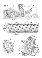
- the reference numeral 10 indicates generally an agricultural combine as utilized in a typical harvesting and threshing operation.
- the combine 10 comprises the conventional portions, including a reel 12 for raking the crop toward the header section 14 which carries a cutter head (not shown) and a conveyor (not shown) for transporting the severed crop rearwardly toward the vehicle 16 which contains the threshing section.
- a threshing rotor 20 embodying the principles of the invention is rotatably mounted in the vehicle 16 and suitable drive means (not shown) are provided for rotating the rotor and actuating the other moveable members of the combine in conventional fashion.
- the rotor 20 is mounted with its longitudinal axis in substantial alignment with the direction of travel of the combine although the same could likewise be mounted transversely to the travel depending on the design of the particular combine.
- Rotor 20 comprises an elongated drum 22 having a cylindrical wall 24, a rear end wall 26, and a front end wall 28. Projecting from the front end wall 28 are a mounting shaft 30 and a plurality of vanes or impeller blades 32 which serve to convey the severed crop material rearwardly to be acted upon by the outer surface of the cylindrical wall 24.
- mounting lug 35 is rigidly secured, as by welding, to the cylindrical wall 24.
- mounting lug 35 comprises an open, frusto-pyramidal member having a front or leading wall 36, sidewalls 38 and 40, and a rear or trailing wall 42, said walls tapering upwardly toward an integral top wall 44.
- Top wall 44 is provided with a connector-receiving hole 46 and a rear wall 42 is formed with an access opening 48 dimensioned to permit entry into the interior of the lug 35 by a tool or finger for purposes which will become apparent as the description proceeds.
- Each of the walls 36, 38, 40, and 42 comprises a bottom flange 50 which is rigidly secured to the cylindrical wall 24 by suitable welding.
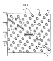
- Mounting lugs 35 are secured to the cylindrical wall 24 to provide an array of helical rows, circumferential rows and longitudinal rows over the entire surface of said wall.
- a preferred arrangement of the lugs 35 is illustrated in FIG. 5 of the drawings. It will there be seen that the lugs 35 form helical rows such as 52, circumferential rows such as 54, and staggered longitudinal rows such as 56. Rotation of the drum 22 would normally be in the upward direction as indicated by the arrow in FIG. 5, so that the closed, front walls 36 of the lugs 35 are leading and contact the crop material first.
- Thresher elements of various forms and shapes are selectively connectable to the lugs 35 as required.
- a bar rasp 60 having a serrated top wall 62 formed with a connector-receiving hole 64 therein.
- Rasp bar 60 has a tapered front wall 66 and comprises a generally frusto-pyramidal form which opens to the rear thereof and is of complementary configuration with the lug 35.
- the rasp bar 60 thus may be connected in contour-accommodating relationship to a lug 35 with suitable connectors such as bolts 67, washers 68 and nuts 69, with the lug opening 48 providing access for a suitable tool for the connection or removal of such connectors.
- FIGS. 8 and 9 illustrate a rasp bar 60' of similar configuration and operation, but having an additional rear spike 61 projecting from the top wall 62'.
- FIGS. 10 and 11 illustrate a straight bar 70 comprising an elongated top wall 72 formed with a pair of connector-receiving openings 74,74, a solid front wall 76, and a pair of hollow end segments 78,78 adapted to fit over a pair of lugs 35 in substantial contour accommodating relationship.
- the bar 70 is connectable to a pair of longitudinally aligned lugs 35.
- FIGS. 12 and 13 there is illustrated a straight bar 70' of substantially identical configuration and operation, but in which the top wall 72' is formed with rasps or serrations 71.
- FIGS. 14 and 15 illustrate a helical kicker bar 80 comprising a top wall 82, a solid front wall 84, and a pair of end portions 86,86 adapted to receive therein a pair of lugs 35.
- Top wall 82 is formed with connector-receiving openings 88,88.
- the kicker bar 80 is formed with curvature as the arc of a helix complementary to the helical curvature of the cylindrical wall 24. As illustrated in FIG. 5, the kicker bar 80 thus may be connected to a pair of helially aligned lugs 35.
- FIGS. 16 and 17 there is illustrated a helical rasp-kicker bar 80' of substantially identical configuration and operation, but in which the top wall 82' is formed with rasps or serrations 81.
- the various thresher elements may be readily and releasably connected to the rotor 20 in an almost limitless variety of patterns as desired or required for the most efficient threshing operations.
- thresher elements may be utilized, it being necessary only that they be releasably connectable to one or a pair of lugs as indicated.
- lugs 35 may be employed.
Landscapes
- Life Sciences & Earth Sciences (AREA)
- Environmental Sciences (AREA)
- Threshing Machine Elements (AREA)
Applications Claiming Priority (2)
| Application Number | Priority Date | Filing Date | Title |
|---|---|---|---|
| US75831385A | 1985-07-24 | 1985-07-24 | |
| US758313 | 1985-07-24 |
Publications (2)
| Publication Number | Publication Date |
|---|---|
| EP0216060A1 true EP0216060A1 (de) | 1987-04-01 |
| EP0216060B1 EP0216060B1 (de) | 1990-10-17 |
Family
ID=25051292
Family Applications (1)
| Application Number | Title | Priority Date | Filing Date |
|---|---|---|---|
| EP19860110020 Expired EP0216060B1 (de) | 1985-07-24 | 1986-07-21 | Konvertierbarer Dreschrotor |
Country Status (9)
| Country | Link |
|---|---|
| EP (1) | EP0216060B1 (de) |
| AU (1) | AU599321B2 (de) |
| CA (1) | CA1293900C (de) |
| DE (1) | DE3674975D1 (de) |
| DK (1) | DK164683C (de) |
| HU (1) | HU197158B (de) |
| NZ (1) | NZ216943A (de) |
| PL (1) | PL152330B1 (de) |
| SU (1) | SU1501909A3 (de) |
Cited By (11)
| Publication number | Priority date | Publication date | Assignee | Title |
|---|---|---|---|---|
| EP0340875A1 (de) * | 1988-05-06 | 1989-11-08 | New Holland Belgium N.V. | Axial-Fluss-Erntemaschine |
| EP0340876A1 (de) * | 1988-05-06 | 1989-11-08 | Ford New Holland N.V. | Axial-Fluss-Erntemaschine |
| US4889517A (en) * | 1989-05-05 | 1989-12-26 | Ford New Holland, Inc. | Overlapping rasp bar rotor for axial flow combines |
| US4936810A (en) * | 1989-05-05 | 1990-06-26 | Ford New Holland, Inc. | Crop thinning elements for axial flow combine |
| DE4232450A1 (de) * | 1992-09-28 | 1994-03-31 | Claas Ohg | Selbstfahrender Mähdrescher |
| RU2181237C2 (ru) * | 2000-02-29 | 2002-04-20 | Федорова Ольга Алексеевна | Молотильно-сепарирующее устройство |
| GB2407749A (en) * | 2003-11-06 | 2005-05-11 | Cnh Belgium Nv | Axial flow combine harvester with adaptable threshing unit |
| GB2407750A (en) * | 2003-11-06 | 2005-05-11 | Cnh Belgium Nv | Axial flow combine harvester with adaptable separating unit |
| WO2014014976A1 (en) * | 2012-07-18 | 2014-01-23 | Cnh America Llc | Threshing element for harvesters |
| WO2014117450A1 (zh) * | 2013-02-04 | 2014-08-07 | 福田雷沃国际重工股份有限公司 | 导草板角度可调的滚筒盖 |
| CN116686534A (zh) * | 2022-03-01 | 2023-09-05 | Cnh工业比利时股份有限公司 | 用于农业器具的纹杆配置 |
Families Citing this family (4)
| Publication number | Priority date | Publication date | Assignee | Title |
|---|---|---|---|---|
| US5083977A (en) * | 1991-03-15 | 1992-01-28 | Deere & Company | Rasp bars for directing crop into an axial separator |
| US5152717A (en) * | 1991-05-10 | 1992-10-06 | Deere & Company | Tooth mounting assembly for axial separator |
| RU2245014C1 (ru) * | 2003-04-30 | 2005-01-27 | Северо-Западный научно-исследовательский институт механизации и электрификации сельского хозяйства | Молотильное устройство |
| DE102004048084A1 (de) * | 2004-09-30 | 2006-04-13 | Claas Selbstfahrende Erntemaschinen Gmbh | Mitnehmer auf einer Zuführtrommel eines selbstfahrenden Mähdreschers |
Citations (5)
| Publication number | Priority date | Publication date | Assignee | Title |
|---|---|---|---|---|
| GB189510793A (en) * | 1895-05-31 | 1895-10-05 | Harry Fisher | Improvements in and relating to Beater Plates of Threshing Machines. |
| US855461A (en) * | 1906-12-26 | 1907-06-04 | George Laczay | Threshing-machine. |
| DE2233018A1 (de) * | 1971-07-06 | 1973-01-25 | Clayson Nv | Maehdrescher der axialflussbauart |
| EP0097988A1 (de) * | 1982-06-24 | 1984-01-11 | Sperry N.V. | Universaler Dreschzylinder |
| US4505279A (en) * | 1983-08-08 | 1985-03-19 | Sperry Corporation | Staggered spiral rasp bar segments for axial flow combines |
-
1986
- 1986-03-27 CA CA000505331A patent/CA1293900C/en not_active Expired - Lifetime
- 1986-05-07 HU HU189086A patent/HU197158B/hu not_active IP Right Cessation
- 1986-07-03 PL PL26044986A patent/PL152330B1/pl unknown
- 1986-07-15 AU AU60167/86A patent/AU599321B2/en not_active Ceased
- 1986-07-21 EP EP19860110020 patent/EP0216060B1/de not_active Expired
- 1986-07-21 DE DE8686110020T patent/DE3674975D1/de not_active Expired - Lifetime
- 1986-07-23 NZ NZ21694386A patent/NZ216943A/en unknown
- 1986-07-23 SU SU864027812A patent/SU1501909A3/ru active
- 1986-07-23 DK DK350586A patent/DK164683C/da not_active IP Right Cessation
Patent Citations (5)
| Publication number | Priority date | Publication date | Assignee | Title |
|---|---|---|---|---|
| GB189510793A (en) * | 1895-05-31 | 1895-10-05 | Harry Fisher | Improvements in and relating to Beater Plates of Threshing Machines. |
| US855461A (en) * | 1906-12-26 | 1907-06-04 | George Laczay | Threshing-machine. |
| DE2233018A1 (de) * | 1971-07-06 | 1973-01-25 | Clayson Nv | Maehdrescher der axialflussbauart |
| EP0097988A1 (de) * | 1982-06-24 | 1984-01-11 | Sperry N.V. | Universaler Dreschzylinder |
| US4505279A (en) * | 1983-08-08 | 1985-03-19 | Sperry Corporation | Staggered spiral rasp bar segments for axial flow combines |
Cited By (16)
| Publication number | Priority date | Publication date | Assignee | Title |
|---|---|---|---|---|
| EP0340875A1 (de) * | 1988-05-06 | 1989-11-08 | New Holland Belgium N.V. | Axial-Fluss-Erntemaschine |
| EP0340876A1 (de) * | 1988-05-06 | 1989-11-08 | Ford New Holland N.V. | Axial-Fluss-Erntemaschine |
| US4946419A (en) * | 1988-05-06 | 1990-08-07 | Ford New Holland, Inc. | Axial flow harvesting machine |
| US4964838A (en) * | 1988-05-06 | 1990-10-23 | Ford New Holland, Inc. | Low profile mounts for axial flow combine rotor |
| US4889517A (en) * | 1989-05-05 | 1989-12-26 | Ford New Holland, Inc. | Overlapping rasp bar rotor for axial flow combines |
| US4936810A (en) * | 1989-05-05 | 1990-06-26 | Ford New Holland, Inc. | Crop thinning elements for axial flow combine |
| DE4232450A1 (de) * | 1992-09-28 | 1994-03-31 | Claas Ohg | Selbstfahrender Mähdrescher |
| US5454758A (en) * | 1992-09-28 | 1995-10-03 | Claas Ohg | Self-propelling harvester thresher |
| RU2181237C2 (ru) * | 2000-02-29 | 2002-04-20 | Федорова Ольга Алексеевна | Молотильно-сепарирующее устройство |
| GB2407749A (en) * | 2003-11-06 | 2005-05-11 | Cnh Belgium Nv | Axial flow combine harvester with adaptable threshing unit |
| GB2407750A (en) * | 2003-11-06 | 2005-05-11 | Cnh Belgium Nv | Axial flow combine harvester with adaptable separating unit |
| WO2014014976A1 (en) * | 2012-07-18 | 2014-01-23 | Cnh America Llc | Threshing element for harvesters |
| US8636569B1 (en) | 2012-07-18 | 2014-01-28 | Cnh America Llc | Threshing element for harvesters |
| WO2014117450A1 (zh) * | 2013-02-04 | 2014-08-07 | 福田雷沃国际重工股份有限公司 | 导草板角度可调的滚筒盖 |
| CN116686534A (zh) * | 2022-03-01 | 2023-09-05 | Cnh工业比利时股份有限公司 | 用于农业器具的纹杆配置 |
| US20230276736A1 (en) * | 2022-03-01 | 2023-09-07 | Cnh Industrial Belgium N.V. | Rasp bar configuration for an agricultural implement |
Also Published As
| Publication number | Publication date |
|---|---|
| DK350586D0 (da) | 1986-07-23 |
| SU1501909A3 (ru) | 1989-08-15 |
| EP0216060B1 (de) | 1990-10-17 |
| DK164683B (da) | 1992-08-03 |
| PL152330B1 (en) | 1990-12-31 |
| CA1293900C (en) | 1992-01-07 |
| AU6016786A (en) | 1987-01-29 |
| AU599321B2 (en) | 1990-07-19 |
| HUT41584A (en) | 1987-05-28 |
| DK164683C (da) | 1992-12-28 |
| NZ216943A (en) | 1988-05-30 |
| HU197158B (en) | 1989-03-28 |
| DE3674975D1 (de) | 1990-11-22 |
| DK350586A (da) | 1987-01-25 |
Similar Documents
| Publication | Publication Date | Title |
|---|---|---|
| US5035675A (en) | Convertible combine rotor | |
| EP0216060A1 (de) | Konvertierbarer Dreschrotor | |
| EP0340876B1 (de) | Axial-Fluss-Erntemaschine | |
| CA1044981A (en) | Rotary combine with improved concave | |
| US4031901A (en) | Concave for an axial flow type combine | |
| JP5022269B2 (ja) | 扱胴 | |
| US5192245A (en) | Thresher elements for a combine | |
| US2833288A (en) | Combine having removable concave | |
| GB1399601A (en) | Harvesting machines | |
| US5192246A (en) | Rotor assembly for a combine | |
| US4117849A (en) | Rotary combine | |
| CN215602015U (zh) | 一种双滚筒脱粒装置及收割机 | |
| DE2729012A1 (de) | Maehdrescher | |
| JP2017176052A (ja) | コンバイン | |
| CA2380995C (en) | Beater for a combine harvester | |
| EP0162431A1 (de) | Erntebergungsmaschine | |
| EP1500323B1 (de) | Erntegutbearbeitungselement für einen Rotor einer Gutbearbeitungseinrichtung eines Mähdreschers | |
| DE2652162A1 (de) | Maehdrescher der axialflussbauart | |
| EP1559307B1 (de) | Dreschwerk für Mähdrescher | |
| EP0097988A1 (de) | Universaler Dreschzylinder | |
| JP5797940B2 (ja) | コンバインの扱胴 | |
| SU978773A1 (ru) | Отбойный битер дл зернового комбайна | |
| JP6335514B2 (ja) | 脱穀装置 | |
| JPH0627083Y2 (ja) | 脱穀装置 | |
| CA2596620C (en) | Step rotor |
Legal Events
| Date | Code | Title | Description |
|---|---|---|---|
| PUAI | Public reference made under article 153(3) epc to a published international application that has entered the european phase |
Free format text: ORIGINAL CODE: 0009012 |
|
| AK | Designated contracting states |
Kind code of ref document: A1 Designated state(s): BE DE FR GB IT |
|
| 17P | Request for examination filed |
Effective date: 19870904 |
|
| 17Q | First examination report despatched |
Effective date: 19880906 |
|
| GRAA | (expected) grant |
Free format text: ORIGINAL CODE: 0009210 |
|
| AK | Designated contracting states |
Kind code of ref document: B1 Designated state(s): BE DE FR GB IT |
|
| ITF | It: translation for a ep patent filed | ||
| REF | Corresponds to: |
Ref document number: 3674975 Country of ref document: DE Date of ref document: 19901122 |
|
| ET | Fr: translation filed | ||
| PLBE | No opposition filed within time limit |
Free format text: ORIGINAL CODE: 0009261 |
|
| STAA | Information on the status of an ep patent application or granted ep patent |
Free format text: STATUS: NO OPPOSITION FILED WITHIN TIME LIMIT |
|
| 26N | No opposition filed | ||
| ITTA | It: last paid annual fee | ||
| REG | Reference to a national code |
Ref country code: GB Ref legal event code: 732E |
|
| REG | Reference to a national code |
Ref country code: GB Ref legal event code: IF02 |
|
| PGFP | Annual fee paid to national office [announced via postgrant information from national office to epo] |
Ref country code: GB Payment date: 20030612 Year of fee payment: 18 |
|
| PGFP | Annual fee paid to national office [announced via postgrant information from national office to epo] |
Ref country code: FR Payment date: 20030702 Year of fee payment: 18 |
|
| PGFP | Annual fee paid to national office [announced via postgrant information from national office to epo] |
Ref country code: DE Payment date: 20030731 Year of fee payment: 18 |
|
| PGFP | Annual fee paid to national office [announced via postgrant information from national office to epo] |
Ref country code: BE Payment date: 20030811 Year of fee payment: 18 |
|
| PG25 | Lapsed in a contracting state [announced via postgrant information from national office to epo] |
Ref country code: GB Free format text: LAPSE BECAUSE OF NON-PAYMENT OF DUE FEES Effective date: 20040721 |
|
| PG25 | Lapsed in a contracting state [announced via postgrant information from national office to epo] |
Ref country code: BE Free format text: LAPSE BECAUSE OF NON-PAYMENT OF DUE FEES Effective date: 20040731 |
|
| BERE | Be: lapsed |
Owner name: *J. I. CASE CY Effective date: 20040731 |
|
| PG25 | Lapsed in a contracting state [announced via postgrant information from national office to epo] |
Ref country code: DE Free format text: LAPSE BECAUSE OF NON-PAYMENT OF DUE FEES Effective date: 20050201 |
|
| GBPC | Gb: european patent ceased through non-payment of renewal fee |
Effective date: 20040721 |
|
| PG25 | Lapsed in a contracting state [announced via postgrant information from national office to epo] |
Ref country code: FR Free format text: LAPSE BECAUSE OF NON-PAYMENT OF DUE FEES Effective date: 20050331 |
|
| REG | Reference to a national code |
Ref country code: FR Ref legal event code: ST |
|
| PG25 | Lapsed in a contracting state [announced via postgrant information from national office to epo] |
Ref country code: IT Free format text: LAPSE BECAUSE OF NON-PAYMENT OF DUE FEES;WARNING: LAPSES OF ITALIAN PATENTS WITH EFFECTIVE DATE BEFORE 2007 MAY HAVE OCCURRED AT ANY TIME BEFORE 2007. THE CORRECT EFFECTIVE DATE MAY BE DIFFERENT FROM THE ONE RECORDED. Effective date: 20050721 |
|
| BERE | Be: lapsed |
Owner name: *J. I. CASE CY Effective date: 20040731 |