EP0216068A1 - Enrouleur pour ceinture de sécurité - Google Patents
Enrouleur pour ceinture de sécurité Download PDFInfo
- Publication number
- EP0216068A1 EP0216068A1 EP86110214A EP86110214A EP0216068A1 EP 0216068 A1 EP0216068 A1 EP 0216068A1 EP 86110214 A EP86110214 A EP 86110214A EP 86110214 A EP86110214 A EP 86110214A EP 0216068 A1 EP0216068 A1 EP 0216068A1
- Authority
- EP
- European Patent Office
- Prior art keywords
- reel
- sensor
- belt
- acceleration
- inertia weight
- Prior art date
- Legal status (The legal status is an assumption and is not a legal conclusion. Google has not performed a legal analysis and makes no representation as to the accuracy of the status listed.)
- Granted
Links
- 230000001133 acceleration Effects 0.000 claims abstract description 33
- 238000000605 extraction Methods 0.000 claims description 3
- 230000000717 retained effect Effects 0.000 description 2
- 238000012986 modification Methods 0.000 description 1
- 230000004048 modification Effects 0.000 description 1
Images
Classifications
-
- B—PERFORMING OPERATIONS; TRANSPORTING
- B60—VEHICLES IN GENERAL
- B60R—VEHICLES, VEHICLE FITTINGS, OR VEHICLE PARTS, NOT OTHERWISE PROVIDED FOR
- B60R22/00—Safety belts or body harnesses in vehicles
- B60R22/34—Belt retractors, e.g. reels
- B60R22/36—Belt retractors, e.g. reels self-locking in an emergency
- B60R22/405—Belt retractors, e.g. reels self-locking in an emergency responsive to belt movement and vehicle movement
-
- B—PERFORMING OPERATIONS; TRANSPORTING
- B60—VEHICLES IN GENERAL
- B60R—VEHICLES, VEHICLE FITTINGS, OR VEHICLE PARTS, NOT OTHERWISE PROVIDED FOR
- B60R22/00—Safety belts or body harnesses in vehicles
- B60R22/34—Belt retractors, e.g. reels
- B60R22/36—Belt retractors, e.g. reels self-locking in an emergency
- B60R22/41—Belt retractors, e.g. reels self-locking in an emergency with additional means for preventing locking during unwinding under predetermined conditions
Definitions
- THE PRESENT INVENTION relates to a seat belt retractor reel and more particularly to a seat belt retractor reel suitable for use in a vehicle such as a motor car.
- a typical seat belt arrangement incorporates a retractor reel adapted to retract the seat belt when the belt is not in use.
- a typical retractor reel is provided with a mechanism adapted to lock the shaft of the reel when an accident arises.
- Such a mechanism may include a sensor which is responsive to acceleration or deceleration of the vehicle in such a way that if an acceleration or deceleration in excess of a predetermined limit is detected the sensor responds to cause the shaft of the reel to be locked.
- a sensor may comprise a pendulum, or a ball in a cup, or a member adapted to topple over when subjected to a predetermined force.
- various prior art reels also include a sensor responsive to the withdrawal of the belt from the reel, the sensor being adapted to respond to seat belt withdrawal in excess of a predetermined velocity or in excess of a predetermined speed, the sensor being adapted to lock the shaft of the reel if the belt is withdrawn at an excessive speed or with an excessive acceleration.
- a sensor incorporates an inertia weight loosely mounted on the shaft and spring biassed to follow movement of the shaft. On rapid movement of the shaft the inertia weight is unable to follow the movement of the shaft, and thus a relative movement occurs between the inertia weight and the shaft. The locking mechanism operates in response to this relative movement.
- an automatic seat belt system when a person enters a motor vehicle and sits in the seat, the seat belt is automatically located in position retaining the person in the seat.
- an automatic seat belt system incorporates a track that is built into the motor vehicle, and one or more carriages are provided which move along the track. The or each carriage carries part of the seat belt.
- the carriages move along the track, withdrawing seat belt from a retractor reel, and the carriages move in such a way that the seat belt is located correctly on the person sitting in the vehicle seat, the seat belt then being clamped or retained in position.
- the sensor that is responsive to vehicle acceleration or deceleration is also responsive to an inclination of the vehicle, since typically the sensor comprises a pendulum, or a ball in a cup, or an element which topples over when subjected to appropriate forces.
- the sensor comprises a pendulum, or a ball in a cup, or an element which topples over when subjected to appropriate forces.
- a further problem can arise if a conventional prior art reel is utilised with an automatic seat belt system as described since if the carriage withdraws the belt from the reel with a speed or acceleration which is in excess of the speed or acceleration that causes the sensor responsive to belt movement to react, again the reel will become locked, thus preventing the further withdrawal of belt.
- the present invention seeks to provide a seat belt system in which the above-described problem is reduced or obviated.
- a retractor reel for a vehicle safety belt arrangement comprising rotatable means on to which part of the safety belt may be wound, locking means adapted to lock the rotatable means in position to prevent the withdrawal of belt therefrom, sensor means adapted to actuate the locking means, said sensor means comprising at least one sensor element either responsive to the speed or acceleration of belt withdrawal, or responsive to the acceleration or deceleration of the vehicle in which the reel is fitted, means being provided selectively to retain said sensor element in an inoperative position.
- said sensor means comprise a first sensor element responsive to the speed or acceleration of belt withdrawal, a second sensor element responsive to the acceleration and deceleration of the vehicle in which the reel is fitted, means being provided selectively to retain both said sensor elements in an inoperative position.
- said selectively operable means are actuated by means of a solenoid.
- the reel may comprise a sensor element responsive to the speed or acceleration of belt withdrawal from the reel, said sensor including an inertia weight mounted about the axis of said rotatable means and biassed to move with the rotatable means by resilient means, said sensor element being arranged to actuate said locking means when a predetermined rotational movement between the inertia weight and the shaft is exceeded, said selectively operable means being adapted to retain the inertia weight in a predetermined position relative to the rotatable means.
- said inertia weight is provided with a portion which extends diametrically of the axis of said rotatable means, transversely to the axis, said selectively operable means including an element movable axially including a portion adapted to engage and retain said diametrically extending portion of the inertia weight, so that the inertia weight co-rotates with the rotatable means.
- said axially movable element comprises a plunger, the end face of the plunger being provided with a diametrically extending groove adapted to engage and retain the diametrically extending portion of the inertia weight, said plunger being provided with means engaging said rotatable means so that at least part of the plunger co-rotates with the rotatable means, thus causing the inertia weight to co-rotate with the rotatable means.
- the plunger comprises a head with a stud rotatably mounted thereon, said stud defining one or more cam faces engageable with a cam element such that movement of the cam element causes the plunger to be driven into and out of the engagement with the diametrically extending portion of the inertia weight.
- the reel may comprise a sensor responsive to acceleration or deceleration of a vehicle in which the reel is fitted, said sensor being constituted by an element which moves from a first predetermined position to a second predetermined position when an acceleration or deceleration in excess of a predetermined limit is experienced, such movement causing a corresponding movement of a locking mechanism, the said selectively operable retaining means being adapted to retain said element in the first position.
- said selectively operable retaining means exert a pressure on part of the locking mechanism actuated by said element, the pressure being adapted to retain the movable element in the first position.
- the part of the selectively operable means applying the pressure to the locking mechanism is resilient.
- the said element is in the form of a "standing man”.
- actuation of the or each sensor causes a carrier wheel to rotate on the subsequent extraction of belt from the reel, movement of the carrier wheel bringing locking elements into engagement with one or more toothed wheels carried by rotatable means to lock the rotatable means in position.
- two diametrically opposed locking bars are provided, said locking bars being engageable with two toothed wheels carried by the rotatable means, the toothed wheels being located on either side of a side wall of a housing in which the rotatable means is mounted, the locking bars passing through apertures in the end wall of the housing.
- This invention also relates to a seat belt arrangement, such as an automatic seat belt arrangement, incorporating such a reel.
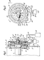
- Figure 1 illustrates part of a retractor reel for receiving a webbing strap forming part of the seat belt arrangement. The strap is not shown.
- One end of the strap may be mounted, in a conventional manner, on a shaft 1 which is rotatably mounted in a housing 2 having endwalls 3 which extend perpendicularly to the axis of the shaft 1.
- the right hand end of the shaft 1 is illustrated in Figure 1 and it can be seen that the shaft 1 is formed integrally with two toothed wheels 4, 5 which are located on either side of the end wall 3 of the housing. It will thus be appreciated that part of the shaft 1 passes through an aperture 6 formed in the end wall 3.
- two locking bars 7, 8 are provided which also extend through corresponding apertures 9, 10 formed in the end wall 3 of the housing.
- the locking bars are carried in apertures 11, 12 formed in a locking bar carrier wheel 13 which is rotatably mounted about the part of the shaft 1 located between the end wall 3 of the housing and the toothed wheel 5.
- the arrangement is such that on rotation of the carrier wheel 13 the locking bars 7, 8 are brought into engagement with the toothed peripheries of the toothed wheels 4, 5 thus serving to lock the shaft against further rotation.
- Means are provided (not shown) resiliently to bias the carrier wheel 13 to a position in which the locking bars 7, 8 are disengaged from the toothed peripheries of the wheels 4, 5 thus permitting free rotation of the shaft 1.
- the shaft 1 is provided with an extension or end piece in the form of two inwardly facing arcuate lugs 14 (which can be seen most clearly in Figure 2) each of the arcuate lugs having, in its inner face, a recess or rebate 15.
- the arcuate lugs effectively form a boss, and a wheel 16 having a toothed outer periphery 17 is carried on the boss.
- the wheel 16 is so mounted that it co-rotates with the shaft 1.
- Carried in a recess 18 formed in the wheel 16 is an annular inertia weight 19.
- the annular weight 19 has a diametrically extending cross piece 20 which extends through the boss 14.
- a projecting pin 22 On the radially innermost portion 21 of the wheel 16 a projecting pin 22 carries a locking lever 23 which is pivotally movable about the pin 22.
- the locking lever is biassed to an inner position (illustrated in Figure 2) by means of a spring 24, one end of which is connected to the free end 25 of the locking lever 23, the other end of the spring 24 being connected to another pin 26 mounted on the radially innermost part 21 of the wheel 16.
- the pins 22 and 26 are diametrically opposed.
- the inertia weight 19 is provided with a projecting pin 27 which engages the underside of the lever 23.
- the inertia weight 19 and the associated elements described above are effectively a sensor which is responsive to the speed or acceleration of belt withdrawal in the direction of the arrow 28. If the belt is only withdrawn slowly, or with a low acceleration, the inertia weight 19 will be able to follow the movement of the shaft 1 without the locking lever 23 being actuated. However, if the belt is withdrawn at a high speed or with a high acceleration the locking lever 23 will be actuated.
- a sensor responsive to vehicle speed is also provided, this sensor being constituted by a "standing man” 30 of a conventional design.
- the "standing man” is a small weight retained in an appropriate cup or hollow, and so designed that when subjected to a predetermined acceleration or deceleration the weight will topple over.
- the weight defines a recess 31 in the upper part thereof, and a follower 32 engages in the recess. When the weight topples the follower is lifted up slightly.
- the follower 32 is formed integrally with a movement amplifying lever 33, and the movement amplifying lever 33 engages a locking lever 34 having a tooth or detent 35 which, when the "standing man” topples is brought into engagement with the toothed periphery 17 of the wheel 16.
- the lever 34 is pivoted by means of a pivot pin 36 to a lug 37 that is formed integrally with the carrier wheel 13.
- means which can be selectively activated to retain both the belt withdrawal sensor (as constituted by the inertia weight 19 and the associated mechansim) and the vehicle acceleration/deceleration sensor (as constituted by the "standing man” 30 and the associated mechanism) in the inoperative position.
- this mechanism can be activated at appropriate times, thus holding both the sensors in the inoperative position, to permit seat belt to be withdrawn from the reel regardless of the speed at which the belt is withdrawn and also regardless of whether the vehicle in which the seat belt assembly is mounted is parked on a slope.
- the means which retain the sensors in the inoperative position are actuated by means of a solenoid 38 which, when activated, draws an arm 39 downwardly as indicated by the arrow 40.
- the arm carries a resilient extension 41 which, when the solenoid is not activated, is located immediately above the movement amplifying lever 33. However, when the solenoid is activated the resilient extension 41 engages the upper surface of the lever 33, and thus exerts a downward bias on the follower 32.
- the concave configuration of the recess 31 in the upper part of the "standing man” 30 the result is that the "standing man” is returned to an upright position, and thus the locking lever 34 does not have the tooth or detent 35 thereof engaged with the toothed periphery 17 of the wheel 16.
- the resilience of the resilient extention 41 is so chosen that in normal circumstances the "standing man” will be returned to an upright condition when the solenoid 38 is activated. However, for safety reasons, it is preferred that the resilience is such that if, whilst the solenoid 38 is activated, the vehicle in which the described arrangement is mounted is subjected to a severe acceleration or deceleration, then the "standing man” 30 will still be able to topple, forcing the movement amplifying lever 33 upwardly against the resilient bias imparted thereto by the resilient projection 41. Thus if, for example, the solenoid 38 becomes jammed, the seat belt mechanism will still provide some degree of protection to a person wearing the seat belt if an accident arises.
- the arm 39 associated with the solenoid extends upwardly and supports a further substantially rigid arm 42 which carries a sloping or cam portion 43.
- the sloping or cam portion 43 passes through a passage 44 provided with sloping faces 45 adapted to cooperate with the cam portion 43 of the arm 42.
- the passage 44 is formed in a stud 46 which carries a rotatable head 47 which is located between the arcuate lugs 14 provided on the extension of the shaft 1.
- the head and stud together form a plunger.
- a transverse groove 48 is formed in the face of the rotatable head 47 which faces away from the stud 46 and is dimensioned to receive the cross piece 20 that forms part of the inertia weight 19.
- the head 47 is provided with two diametrically opposed projections 49 which are received within the above-described recesses 15 formed in the arcuate lugs 14. It will thus be appreciated that as the shaft 1 rotates the head 47 can rotate relative to the stud 46.
- the described seat belt reel may be utilised, for example, in conjunction with an automatic seat belt arrangement of the type in which a carriage moves around a track provided in a motor vehicle, movement of the carriage resulting in seat belt being paid out from the reel.
- the solenoid 38 When the carriage is moved the solenoid 38 will be activated, thus retaining the belt sensor and the vehicle sensor in the inoperative position, thus preventing the shaft 1 from being locked.
- the belt can easily be paid out.
- part of the mechanism is resilient so that, even if the solenoid is jammed, if the vehicle is subjected to a severe acceleration or deceleration the vehicle sensor will still operate to lock the shaft.
Landscapes
- Engineering & Computer Science (AREA)
- Mechanical Engineering (AREA)
- Automotive Seat Belt Assembly (AREA)
Applications Claiming Priority (2)
| Application Number | Priority Date | Filing Date | Title |
|---|---|---|---|
| GB8521413 | 1985-08-28 | ||
| GB858521413A GB8521413D0 (en) | 1985-08-28 | 1985-08-28 | Seat belt |
Publications (2)
| Publication Number | Publication Date |
|---|---|
| EP0216068A1 true EP0216068A1 (fr) | 1987-04-01 |
| EP0216068B1 EP0216068B1 (fr) | 1989-05-24 |
Family
ID=10584387
Family Applications (1)
| Application Number | Title | Priority Date | Filing Date |
|---|---|---|---|
| EP86110214A Expired EP0216068B1 (fr) | 1985-08-28 | 1986-07-24 | Enrouleur pour ceinture de sécurité |
Country Status (5)
| Country | Link |
|---|---|
| US (1) | US4763853A (fr) |
| EP (1) | EP0216068B1 (fr) |
| JP (1) | JPS6253270A (fr) |
| DE (1) | DE3663496D1 (fr) |
| GB (1) | GB8521413D0 (fr) |
Cited By (1)
| Publication number | Priority date | Publication date | Assignee | Title |
|---|---|---|---|---|
| WO2009049754A1 (fr) * | 2007-10-10 | 2009-04-23 | Autoliv Development Ab | Enrouleur de ceinture de sécurité auto-bloquant |
Families Citing this family (12)
| Publication number | Priority date | Publication date | Assignee | Title |
|---|---|---|---|---|
| US4856728A (en) * | 1988-03-21 | 1989-08-15 | General Safety Corporation | Passive seat belt retractor assembly |
| JPH0719931Y2 (ja) * | 1989-01-19 | 1995-05-10 | 株式会社東海理化電機製作所 | ウエビング巻取装置用ロツク機構 |
| US5390874A (en) * | 1993-09-10 | 1995-02-21 | Trw Vehicle Safety Systems Inc. | Vehicle sensitive retractor |
| US5535959A (en) * | 1995-02-21 | 1996-07-16 | Trw Vehicle Safety Systems Inc. | Tension reducing retractor with reduced velocity ratchet |
| US5839790A (en) | 1995-06-06 | 1998-11-24 | Takata Inc. | Remote mechanical sensor and seat belt retractor operated thereby |
| DE10066050B4 (de) * | 2000-04-17 | 2010-05-27 | Trw Automotive Electronics & Components Gmbh & Co. Kg | Gurtaufroller |
| JP5134004B2 (ja) * | 2006-12-02 | 2013-01-30 | オートリブ ディベロップメント エービー | ベルトストラップ感応および車両感応の制御システムの遮断手段を備えているシートベルト巻き取り装置 |
| JP2008213525A (ja) * | 2007-02-28 | 2008-09-18 | Takata Corp | シートベルトリトラクタおよびこれを用いたシートベルト装置 |
| ATE539923T1 (de) * | 2008-03-31 | 2012-01-15 | Ashimori Ind Co Ltd | Sitzgurtaufroller |
| DE102008052563B4 (de) * | 2008-10-21 | 2015-02-12 | Autoliv Development Ab | Sicherheitsgurtaufroller mit deaktivierbarem Blockiersystem |
| DE102012017093A1 (de) * | 2012-08-29 | 2014-05-15 | GM Global Technology Operations, LLC (n.d. Ges. d. Staates Delaware) | Sicherheitsgurtaufroller für ein Kraftfahrzeug |
| DE102013008277B4 (de) * | 2013-05-15 | 2022-10-13 | Zf Automotive Germany Gmbh | Verfahren zum Straffen eines unbenutzten Fahrzeuggurts |
Citations (9)
| Publication number | Priority date | Publication date | Assignee | Title |
|---|---|---|---|---|
| FR2224986A5 (en) * | 1973-04-05 | 1974-10-31 | Peugeot & Renault | Inertia reel for safety belts - has plunger which allows belt to remain free except on rapid deceleration |
| US4036322A (en) * | 1973-04-25 | 1977-07-19 | Takada Takezo | Automatic locking safety belt retractor reel |
| DE2658747A1 (de) * | 1976-12-24 | 1978-06-29 | Autoflug Gmbh | Sicherheitssitz, insbesondere fuer kraftfahrzeuge |
| US4181326A (en) * | 1978-01-25 | 1980-01-01 | American Safety Equipment Corporation | Vehicle sensing inertia reel lockup inhibitors |
| FR2441393A1 (fr) * | 1978-11-20 | 1980-06-13 | Kangol Magnet Ltd | Ceinture de securite pour vehicule |
| US4244600A (en) * | 1978-04-18 | 1981-01-13 | Juichiro Takada | Deactivatable locking retractor for vehicle seat belt systems |
| US4260118A (en) * | 1978-10-04 | 1981-04-07 | Nsk-Warner K.K. | Seat belt retractor |
| DE3532470A1 (de) * | 1984-09-12 | 1986-03-27 | Autoliv Development Ab, Vargarda | Rueckholhaspel fuer einen fahrzeug-sicherheitsgurt |
| DE3441532A1 (de) * | 1984-11-14 | 1986-05-15 | Autoflug GmbH & Co Fahrzeugtechnik, 2084 Rellingen | Selbstsperrender gurtaufroller fuer insbesondere passive sicherheitsgurtsysteme in kraftfahrzeugen |
Family Cites Families (3)
| Publication number | Priority date | Publication date | Assignee | Title |
|---|---|---|---|---|
| JPS521824A (en) * | 1975-06-24 | 1977-01-08 | Nissan Motor Co Ltd | Seat belt retractor |
| DE2750440A1 (de) * | 1977-11-11 | 1979-05-17 | Volkswagenwerk Ag | Sicherheitseinrichtung fuer fahrzeuge, insbesondere personenkraftfahrzeuge |
| US4209186A (en) * | 1978-10-16 | 1980-06-24 | American Safety Equipment Corporation | Lock-up inhibitor for door mounted retractor |
-
1985
- 1985-08-28 GB GB858521413A patent/GB8521413D0/en active Pending
-
1986
- 1986-07-24 EP EP86110214A patent/EP0216068B1/fr not_active Expired
- 1986-07-24 DE DE8686110214T patent/DE3663496D1/de not_active Expired
- 1986-08-26 US US06/900,431 patent/US4763853A/en not_active Expired - Fee Related
- 1986-08-28 JP JP61202610A patent/JPS6253270A/ja active Pending
Patent Citations (9)
| Publication number | Priority date | Publication date | Assignee | Title |
|---|---|---|---|---|
| FR2224986A5 (en) * | 1973-04-05 | 1974-10-31 | Peugeot & Renault | Inertia reel for safety belts - has plunger which allows belt to remain free except on rapid deceleration |
| US4036322A (en) * | 1973-04-25 | 1977-07-19 | Takada Takezo | Automatic locking safety belt retractor reel |
| DE2658747A1 (de) * | 1976-12-24 | 1978-06-29 | Autoflug Gmbh | Sicherheitssitz, insbesondere fuer kraftfahrzeuge |
| US4181326A (en) * | 1978-01-25 | 1980-01-01 | American Safety Equipment Corporation | Vehicle sensing inertia reel lockup inhibitors |
| US4244600A (en) * | 1978-04-18 | 1981-01-13 | Juichiro Takada | Deactivatable locking retractor for vehicle seat belt systems |
| US4260118A (en) * | 1978-10-04 | 1981-04-07 | Nsk-Warner K.K. | Seat belt retractor |
| FR2441393A1 (fr) * | 1978-11-20 | 1980-06-13 | Kangol Magnet Ltd | Ceinture de securite pour vehicule |
| DE3532470A1 (de) * | 1984-09-12 | 1986-03-27 | Autoliv Development Ab, Vargarda | Rueckholhaspel fuer einen fahrzeug-sicherheitsgurt |
| DE3441532A1 (de) * | 1984-11-14 | 1986-05-15 | Autoflug GmbH & Co Fahrzeugtechnik, 2084 Rellingen | Selbstsperrender gurtaufroller fuer insbesondere passive sicherheitsgurtsysteme in kraftfahrzeugen |
Cited By (1)
| Publication number | Priority date | Publication date | Assignee | Title |
|---|---|---|---|---|
| WO2009049754A1 (fr) * | 2007-10-10 | 2009-04-23 | Autoliv Development Ab | Enrouleur de ceinture de sécurité auto-bloquant |
Also Published As
| Publication number | Publication date |
|---|---|
| US4763853A (en) | 1988-08-16 |
| JPS6253270A (ja) | 1987-03-07 |
| EP0216068B1 (fr) | 1989-05-24 |
| GB8521413D0 (en) | 1985-10-02 |
| DE3663496D1 (en) | 1989-06-29 |
Similar Documents
| Publication | Publication Date | Title |
|---|---|---|
| US3991953A (en) | Automatic locking safety belt retractor | |
| US4763853A (en) | Seat belt retractor reel | |
| US4083512A (en) | Independent redundant clutchless retractor | |
| US6598921B2 (en) | Protective device for securing the storage space in the interior of a vehicle | |
| EP0195268A2 (fr) | Dispositif tendeur pour ceinture de sécurité | |
| US4168810A (en) | Novel locking mechanism and reel for retractor | |
| US4262858A (en) | Inertia-responsive actuating device for vehicle seat belt retractors | |
| EP0046308B1 (fr) | Rétracteur de ceinture de siège ayant un arrêt de secours | |
| US4083511A (en) | Seat belt retractor | |
| US4053117A (en) | Automatic locking safety belt retractor | |
| US4456195A (en) | Emergency locking vehicle safety belt retractor | |
| US20050133652A1 (en) | Belt retractor for a vehicle safety belt | |
| US4090678A (en) | Safety belt locking device | |
| IE49157B1 (en) | Double-safety emergency locking belt retractor | |
| US4302030A (en) | Seat belt systems | |
| US3830444A (en) | Safety seat belt assemblies | |
| US4331304A (en) | Emergency lock type retractor | |
| US6364238B1 (en) | Belt retractor with force limiter | |
| EP1279575B1 (fr) | Enrouleur automatique | |
| EP0979187B1 (fr) | Enrouleur | |
| US4014480A (en) | Inertia locking seat belt retractor | |
| US3664600A (en) | Inertia reels for safety belts | |
| US4402473A (en) | Manually operated locking device of seat belt retractor for vehicles | |
| US4856727A (en) | Retractor with cinch | |
| US3942739A (en) | Safety belt construction |
Legal Events
| Date | Code | Title | Description |
|---|---|---|---|
| PUAI | Public reference made under article 153(3) epc to a published international application that has entered the european phase |
Free format text: ORIGINAL CODE: 0009012 |
|
| AK | Designated contracting states |
Kind code of ref document: A1 Designated state(s): DE FR GB IT |
|
| 17P | Request for examination filed |
Effective date: 19870925 |
|
| 17Q | First examination report despatched |
Effective date: 19880923 |
|
| ITF | It: translation for a ep patent filed | ||
| GRAA | (expected) grant |
Free format text: ORIGINAL CODE: 0009210 |
|
| AK | Designated contracting states |
Kind code of ref document: B1 Designated state(s): DE FR GB IT |
|
| REF | Corresponds to: |
Ref document number: 3663496 Country of ref document: DE Date of ref document: 19890629 |
|
| ET | Fr: translation filed | ||
| PLBE | No opposition filed within time limit |
Free format text: ORIGINAL CODE: 0009261 |
|
| STAA | Information on the status of an ep patent application or granted ep patent |
Free format text: STATUS: NO OPPOSITION FILED WITHIN TIME LIMIT |
|
| 26N | No opposition filed | ||
| ITTA | It: last paid annual fee | ||
| PGFP | Annual fee paid to national office [announced via postgrant information from national office to epo] |
Ref country code: FR Payment date: 19920724 Year of fee payment: 7 |
|
| PG25 | Lapsed in a contracting state [announced via postgrant information from national office to epo] |
Ref country code: FR Effective date: 19940331 |
|
| REG | Reference to a national code |
Ref country code: FR Ref legal event code: ST |
|
| PGFP | Annual fee paid to national office [announced via postgrant information from national office to epo] |
Ref country code: GB Payment date: 19960715 Year of fee payment: 11 |
|
| PGFP | Annual fee paid to national office [announced via postgrant information from national office to epo] |
Ref country code: DE Payment date: 19960802 Year of fee payment: 11 |
|
| PG25 | Lapsed in a contracting state [announced via postgrant information from national office to epo] |
Ref country code: GB Free format text: LAPSE BECAUSE OF NON-PAYMENT OF DUE FEES Effective date: 19970724 |
|
| GBPC | Gb: european patent ceased through non-payment of renewal fee |
Effective date: 19970724 |
|
| PG25 | Lapsed in a contracting state [announced via postgrant information from national office to epo] |
Ref country code: DE Free format text: LAPSE BECAUSE OF NON-PAYMENT OF DUE FEES Effective date: 19980401 |
|
| PG25 | Lapsed in a contracting state [announced via postgrant information from national office to epo] |
Ref country code: IT Free format text: LAPSE BECAUSE OF NON-PAYMENT OF DUE FEES;WARNING: LAPSES OF ITALIAN PATENTS WITH EFFECTIVE DATE BEFORE 2007 MAY HAVE OCCURRED AT ANY TIME BEFORE 2007. THE CORRECT EFFECTIVE DATE MAY BE DIFFERENT FROM THE ONE RECORDED. Effective date: 20050724 |