EP0216202A1 - Moteur électrique - Google Patents
Moteur électrique Download PDFInfo
- Publication number
- EP0216202A1 EP0216202A1 EP86112073A EP86112073A EP0216202A1 EP 0216202 A1 EP0216202 A1 EP 0216202A1 EP 86112073 A EP86112073 A EP 86112073A EP 86112073 A EP86112073 A EP 86112073A EP 0216202 A1 EP0216202 A1 EP 0216202A1
- Authority
- EP
- European Patent Office
- Prior art keywords
- stator
- electric motor
- poles
- rotor
- motor according
- Prior art date
- Legal status (The legal status is an assumption and is not a legal conclusion. Google has not performed a legal analysis and makes no representation as to the accuracy of the status listed.)
- Granted
Links
- 239000004020 conductor Substances 0.000 claims abstract description 32
- 238000004804 winding Methods 0.000 claims description 9
- 229910052772 Samarium Inorganic materials 0.000 claims description 2
- 239000000956 alloy Substances 0.000 claims description 2
- 229910045601 alloy Inorganic materials 0.000 claims description 2
- 229910017052 cobalt Inorganic materials 0.000 claims description 2
- 239000010941 cobalt Substances 0.000 claims description 2
- GUTLYIVDDKVIGB-UHFFFAOYSA-N cobalt atom Chemical compound [Co] GUTLYIVDDKVIGB-UHFFFAOYSA-N 0.000 claims description 2
- KZUNJOHGWZRPMI-UHFFFAOYSA-N samarium atom Chemical compound [Sm] KZUNJOHGWZRPMI-UHFFFAOYSA-N 0.000 claims description 2
- 230000005291 magnetic effect Effects 0.000 description 10
- 239000000523 sample Substances 0.000 description 6
- 150000001875 compounds Chemical class 0.000 description 2
- 238000010276 construction Methods 0.000 description 2
- 239000003302 ferromagnetic material Substances 0.000 description 2
- 210000003128 head Anatomy 0.000 description 2
- 235000014676 Phragmites communis Nutrition 0.000 description 1
- 230000004913 activation Effects 0.000 description 1
- 238000005266 casting Methods 0.000 description 1
- 238000001816 cooling Methods 0.000 description 1
- 230000000694 effects Effects 0.000 description 1
- 230000002349 favourable effect Effects 0.000 description 1
- 230000005294 ferromagnetic effect Effects 0.000 description 1
- 210000001061 forehead Anatomy 0.000 description 1
- 230000006698 induction Effects 0.000 description 1
- 238000009413 insulation Methods 0.000 description 1
- 238000003475 lamination Methods 0.000 description 1
- 238000012423 maintenance Methods 0.000 description 1
- 238000004519 manufacturing process Methods 0.000 description 1
- 230000035699 permeability Effects 0.000 description 1
- 239000000843 powder Substances 0.000 description 1
- 150000002910 rare earth metals Chemical group 0.000 description 1
- 238000007789 sealing Methods 0.000 description 1
Images

Classifications
-
- H—ELECTRICITY
- H02—GENERATION; CONVERSION OR DISTRIBUTION OF ELECTRIC POWER
- H02K—DYNAMO-ELECTRIC MACHINES
- H02K41/00—Propulsion systems in which a rigid body is moved along a path due to dynamo-electric interaction between the body and a magnetic field travelling along the path
- H02K41/02—Linear motors; Sectional motors
- H02K41/03—Synchronous motors; Motors moving step by step; Reluctance motors
- H02K41/031—Synchronous motors; Motors moving step by step; Reluctance motors of the permanent magnet type
-
- B—PERFORMING OPERATIONS; TRANSPORTING
- B60—VEHICLES IN GENERAL
- B60K—ARRANGEMENT OR MOUNTING OF PROPULSION UNITS OR OF TRANSMISSIONS IN VEHICLES; ARRANGEMENT OR MOUNTING OF PLURAL DIVERSE PRIME-MOVERS IN VEHICLES; AUXILIARY DRIVES FOR VEHICLES; INSTRUMENTATION OR DASHBOARDS FOR VEHICLES; ARRANGEMENTS IN CONNECTION WITH COOLING, AIR INTAKE, GAS EXHAUST OR FUEL SUPPLY OF PROPULSION UNITS IN VEHICLES
- B60K25/00—Auxiliary drives
- B60K25/08—Auxiliary drives from a ground wheel, e.g. engaging the wheel tread or rim
-
- B—PERFORMING OPERATIONS; TRANSPORTING
- B60—VEHICLES IN GENERAL
- B60L—PROPULSION OF ELECTRICALLY-PROPELLED VEHICLES; SUPPLYING ELECTRIC POWER FOR AUXILIARY EQUIPMENT OF ELECTRICALLY-PROPELLED VEHICLES; ELECTRODYNAMIC BRAKE SYSTEMS FOR VEHICLES IN GENERAL; MAGNETIC SUSPENSION OR LEVITATION FOR VEHICLES; MONITORING OPERATING VARIABLES OF ELECTRICALLY-PROPELLED VEHICLES; ELECTRIC SAFETY DEVICES FOR ELECTRICALLY-PROPELLED VEHICLES
- B60L13/00—Electric propulsion for monorail vehicles, suspension vehicles or rack railways; Magnetic suspension or levitation for vehicles
- B60L13/03—Electric propulsion by linear motors
-
- B—PERFORMING OPERATIONS; TRANSPORTING
- B60—VEHICLES IN GENERAL
- B60L—PROPULSION OF ELECTRICALLY-PROPELLED VEHICLES; SUPPLYING ELECTRIC POWER FOR AUXILIARY EQUIPMENT OF ELECTRICALLY-PROPELLED VEHICLES; ELECTRODYNAMIC BRAKE SYSTEMS FOR VEHICLES IN GENERAL; MAGNETIC SUSPENSION OR LEVITATION FOR VEHICLES; MONITORING OPERATING VARIABLES OF ELECTRICALLY-PROPELLED VEHICLES; ELECTRIC SAFETY DEVICES FOR ELECTRICALLY-PROPELLED VEHICLES
- B60L15/00—Methods, circuits, or devices for controlling the traction-motor speed of electrically-propelled vehicles
- B60L15/002—Methods, circuits, or devices for controlling the traction-motor speed of electrically-propelled vehicles for control of propulsion for monorail vehicles, suspension vehicles or rack railways; for control of magnetic suspension or levitation for vehicles for propulsion purposes
- B60L15/005—Methods, circuits, or devices for controlling the traction-motor speed of electrically-propelled vehicles for control of propulsion for monorail vehicles, suspension vehicles or rack railways; for control of magnetic suspension or levitation for vehicles for propulsion purposes for control of propulsion for vehicles propelled by linear motors
-
- B—PERFORMING OPERATIONS; TRANSPORTING
- B60—VEHICLES IN GENERAL
- B60L—PROPULSION OF ELECTRICALLY-PROPELLED VEHICLES; SUPPLYING ELECTRIC POWER FOR AUXILIARY EQUIPMENT OF ELECTRICALLY-PROPELLED VEHICLES; ELECTRODYNAMIC BRAKE SYSTEMS FOR VEHICLES IN GENERAL; MAGNETIC SUSPENSION OR LEVITATION FOR VEHICLES; MONITORING OPERATING VARIABLES OF ELECTRICALLY-PROPELLED VEHICLES; ELECTRIC SAFETY DEVICES FOR ELECTRICALLY-PROPELLED VEHICLES
- B60L50/00—Electric propulsion with power supplied within the vehicle
- B60L50/10—Electric propulsion with power supplied within the vehicle using propulsion power supplied by engine-driven generators, e.g. generators driven by combustion engines
- B60L50/15—Electric propulsion with power supplied within the vehicle using propulsion power supplied by engine-driven generators, e.g. generators driven by combustion engines with additional electric power supply
-
- B—PERFORMING OPERATIONS; TRANSPORTING
- B60—VEHICLES IN GENERAL
- B60L—PROPULSION OF ELECTRICALLY-PROPELLED VEHICLES; SUPPLYING ELECTRIC POWER FOR AUXILIARY EQUIPMENT OF ELECTRICALLY-PROPELLED VEHICLES; ELECTRODYNAMIC BRAKE SYSTEMS FOR VEHICLES IN GENERAL; MAGNETIC SUSPENSION OR LEVITATION FOR VEHICLES; MONITORING OPERATING VARIABLES OF ELECTRICALLY-PROPELLED VEHICLES; ELECTRIC SAFETY DEVICES FOR ELECTRICALLY-PROPELLED VEHICLES
- B60L50/00—Electric propulsion with power supplied within the vehicle
- B60L50/30—Electric propulsion with power supplied within the vehicle using propulsion power stored mechanically, e.g. in fly-wheels
-
- H—ELECTRICITY
- H02—GENERATION; CONVERSION OR DISTRIBUTION OF ELECTRIC POWER
- H02K—DYNAMO-ELECTRIC MACHINES
- H02K29/00—Motors or generators having non-mechanical commutating devices, e.g. discharge tubes or semiconductor devices
- H02K29/06—Motors or generators having non-mechanical commutating devices, e.g. discharge tubes or semiconductor devices with position sensing devices
- H02K29/08—Motors or generators having non-mechanical commutating devices, e.g. discharge tubes or semiconductor devices with position sensing devices using magnetic effect devices, e.g. Hall-plates, magneto-resistors
-
- B—PERFORMING OPERATIONS; TRANSPORTING
- B60—VEHICLES IN GENERAL
- B60L—PROPULSION OF ELECTRICALLY-PROPELLED VEHICLES; SUPPLYING ELECTRIC POWER FOR AUXILIARY EQUIPMENT OF ELECTRICALLY-PROPELLED VEHICLES; ELECTRODYNAMIC BRAKE SYSTEMS FOR VEHICLES IN GENERAL; MAGNETIC SUSPENSION OR LEVITATION FOR VEHICLES; MONITORING OPERATING VARIABLES OF ELECTRICALLY-PROPELLED VEHICLES; ELECTRIC SAFETY DEVICES FOR ELECTRICALLY-PROPELLED VEHICLES
- B60L2200/00—Type of vehicles
- B60L2200/26—Rail vehicles
-
- Y—GENERAL TAGGING OF NEW TECHNOLOGICAL DEVELOPMENTS; GENERAL TAGGING OF CROSS-SECTIONAL TECHNOLOGIES SPANNING OVER SEVERAL SECTIONS OF THE IPC; TECHNICAL SUBJECTS COVERED BY FORMER USPC CROSS-REFERENCE ART COLLECTIONS [XRACs] AND DIGESTS
- Y02—TECHNOLOGIES OR APPLICATIONS FOR MITIGATION OR ADAPTATION AGAINST CLIMATE CHANGE
- Y02T—CLIMATE CHANGE MITIGATION TECHNOLOGIES RELATED TO TRANSPORTATION
- Y02T10/00—Road transport of goods or passengers
- Y02T10/60—Other road transportation technologies with climate change mitigation effect
- Y02T10/64—Electric machine technologies in electromobility
-
- Y—GENERAL TAGGING OF NEW TECHNOLOGICAL DEVELOPMENTS; GENERAL TAGGING OF CROSS-SECTIONAL TECHNOLOGIES SPANNING OVER SEVERAL SECTIONS OF THE IPC; TECHNICAL SUBJECTS COVERED BY FORMER USPC CROSS-REFERENCE ART COLLECTIONS [XRACs] AND DIGESTS
- Y02—TECHNOLOGIES OR APPLICATIONS FOR MITIGATION OR ADAPTATION AGAINST CLIMATE CHANGE
- Y02T—CLIMATE CHANGE MITIGATION TECHNOLOGIES RELATED TO TRANSPORTATION
- Y02T10/00—Road transport of goods or passengers
- Y02T10/60—Other road transportation technologies with climate change mitigation effect
- Y02T10/70—Energy storage systems for electromobility, e.g. batteries
-
- Y—GENERAL TAGGING OF NEW TECHNOLOGICAL DEVELOPMENTS; GENERAL TAGGING OF CROSS-SECTIONAL TECHNOLOGIES SPANNING OVER SEVERAL SECTIONS OF THE IPC; TECHNICAL SUBJECTS COVERED BY FORMER USPC CROSS-REFERENCE ART COLLECTIONS [XRACs] AND DIGESTS
- Y02—TECHNOLOGIES OR APPLICATIONS FOR MITIGATION OR ADAPTATION AGAINST CLIMATE CHANGE
- Y02T—CLIMATE CHANGE MITIGATION TECHNOLOGIES RELATED TO TRANSPORTATION
- Y02T10/00—Road transport of goods or passengers
- Y02T10/60—Other road transportation technologies with climate change mitigation effect
- Y02T10/7072—Electromobility specific charging systems or methods for batteries, ultracapacitors, supercapacitors or double-layer capacitors
Definitions
- the invention relates to an electric motor according to the preamble of claim 1.
- the invention has for its object to provide an electric motor with good controllability and high efficiency.
- Electric motors according to the invention have a characteristic which can be adapted to the respective operating conditions and a particularly good, varied control behavior.
- the electric motor according to the invention does not require any sliding contacts that are susceptible to wear and are susceptible to faults, and no collector, because the individual current conductors are switched on in a timely manner in an electronic manner.
- the possible different pole pitch of the stator and rotor provides the advantages of a safe motor start-up, a smooth motor run and a uniform network load, whereby this different pole pitch becomes problem-free only in practice due to the timely electronic activation of the current conductors.
- the design with essentially the same number of stator poles and permanent magnet poles allows an optimally high number of permanent magnets on the rotor circumference; As a result, the magnetic return paths can be carried out both on the rotor between the permanent magnets and on the stator between the stator poles with a smaller cross section, thereby saving on motor weight.
- the motor according to the invention has a high ratio of power or torque to weight or construction volume.
- the current conductors are provided in the form of coils or windings.
- a generator can also be constructed according to the principle of the invention.
- stator and rotor are not intended to mean that the stator is necessarily the part of the electric motor that remains stationary and the rotor is necessarily the moving part of the electric motor. Rather, both options, that is, moving stator with a rotor that remains stationary and stator that remains stationary with a rotor that is moving, can be implemented, even the possibility that both the stator and the rotor move at different speeds. However, the case of the stator which remains stationary is preferred since current must be supplied to it.
- highly coercive permanent magnets made from an alloy of an element from the rare earth group, in particular samarium, with cobalt are preferably used.
- Such magnets make it possible to work with comparatively large gap widths. They are also characterized by a practically straight characteristic curve in the fourth quadrant, which makes them relatively insensitive to changes in gap width and opposing fields, for example by electromagnets.
- Hall generators are particularly preferred as sensors, since they can be conveniently arranged to respond to the magnetic fields of the permanent magnets.
- sensors can also be used, for example reed contacts, photocells, ultrasonic sensors, gas flow sensors, induction sensors or permeability sensors.
- a sensor or a switching device to conduct several current conductors or coils of several stator poles, which are in at least substantially the same relative position to permanent magnet poles switch.
- This can be a group of adjacent stator poles which, despite the different pole pitch of the stator and rotor described, still have an essentially identical relative position to permanent magnet poles.
- it is preferably the simultaneous switching of current conductors of a pair of diametrically opposite stator poles in a stator with an even number of stator poles. It is also possible to connect the current conductors or coils of different stator poles to be switched at the same time either in series or in parallel.
- the single-phase design i.e. the provision of a stator pole essentially per permanent magnetic pole, has the further advantage that the same coils or windings can be used that do not overlap or cross each other, so that no winding heads are required. This enables series production of the coils or windings and facilitates their interchangeability.
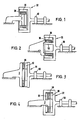
- Figures 1 to 4 show some basic configurations of electric motors.
- the part of the respective electric motor on the right in these figures is rotatably supported with bearings 50 and forms the rotor.
- the actual rotor area is essentially cup-shaped, permanent magnets with alternating polarity being distributed in a ring shape on the inner circumference of the cup.
- the stator 2 is in the form of a roller which is laminated on the outer circumference, the individual laminations being axially packed together.
- the stator 2 carries on the outer circumference axially extending current conductors, not shown in the drawing, in a suitable division.
- the area of the rotor 32 to which the permanent magnets 30 are fastened consists of ferromagnetic material as the return path.
- the current conductors can be inserted, for example, in axially extending grooves in the stator.
- the stator 2 carries a plurality of Hall probes 38 distributed in a ring on the outer circumference, which cooperate with the permanent magnets 30. As soon as it is determined on the Hall sensor side that a rotor-side part and a stator-side part of a magnetic circuit or a plurality of magnetic circuits are in a relative position suitable for the drive, the current conductor or the coil or the current conductors or the coils of this circuit or of these circles switched on automatically.
- the embodiment according to FIG. 2 differs from the embodiment according to FIG. 1 in that the stator area arranged radially inside the ring of the permanent magnets 30 protrudes in a cup-shaped manner and in that an annular projection 52 of the rotor 32 radially within this stator area while maintaining a small air gap to the stator ring is provided.
- the part of the magnetic circuits previously associated with the stator 2 is mainly shifted to the ring projection 52, which rotates at the same speed as the permanent magnets 30. In this way, the eddy current losses can be reduced.
- the stator area located radially between the permanent magnets 30 and the annular projection 52 can also be filled in the form of so-called air flow conductors or air coils or in the form of current conductors or coils, the spaces between which, with the conductor surfaces lying on the outer circumference and on the inner circumference, leaving a casting compound containing ferromagnetic powder are trained.
- the embodiment according to FIG. 3 differs from the embodiment according to FIG. 1 in that the rotor 32 is designed as a disk and in that the permanent magnets are arranged in an axially distributed manner on the end face of the knife facing away from the bearings 50.
- the stator 2 is also disk-shaped and carries the plate pack and the current conductors, not shown, on its end face facing the rotor 32. The individual slats of the disk pack running in the circumferential direction are radially adjacent to one another.
- the embodiment according to FIG. 4 differs from the embodiment according to FIG. 3 in that the rotor 32 has two has interconnected disks on the outer circumference, between which the stator designed as a disk is located.
- a co-rotating, magnetic yoke according to the principle of the embodiment according to FIG. 2 can be provided, or, as shown in the drawing, a series of annularly distributed permanent magnets 30 can be attached there on the end face.
- the stator disk interacts with permanent magnets 30 on both end faces, so that there is a compensation of the axially acting magnetic attraction forces.
- the embodiment according to FIG. 4 can be expanded by adding further stator disks and rotor disks.
- the stator area between the two rotor disks equipped with permanent magnets 30 can, as described in the embodiment according to FIG. 2, be realized with conductors or coils filled with air flow conductors or air coils or sealing compound.
- the center distances of the current conductors of the stator 2 or the center distances of stator poles and the center distances of the permanent magnets 30, in each case in the circumferential direction, are essentially coordinated with one another, although a slightly different division on the stator and on the rotor can be provided to avoid the so-called groove effect.
- FIG. 5 shows an electric motor which is constructed according to the basic principle described in FIG. 1, but with a rotor arranged radially inside the stator. Analogously, however, one can also arrange the stator within the rotor in accordance with the basic principle of FIG. 1, as a result of which the annular gap between the stator and rotor moves further outward and the permanent magnets are pressed against their attachment surface by the centrifugal force.
- the overall cylindrical stator 2 consists of an axially assembled package of - roughly speaking - annular sheets made of ferromagnetic material.
- the stator 2 has stator poles or stator teeth 3 projecting inwards distributed over the inner circumference.
- Each stator tooth 3 has three coils 10 in radial succession.
- Each coil 10 consists of two axial branches and two front branches connecting the axial branches. Each coil is wound from a plurality of wires insulated from one another, but is shown in FIG. 5 as the only thick wire.
- the rotor 31 rotating within the stator 2 carries, on its outer circumference, a series of permanent magnets 30 of alternating polarity, which are provided in an even number and which extend axially and distributed axially.
- the mutually equal distances of the stator teeth 3, measured in the circumferential direction from center to center are so small or larger than the analogously measured center distances of the permanent magnets 30 that one or two pole teeth 3 are more or less as permanent magnets .
- each pole tooth 3 there is a Hall probe 38 which is responsive to the permanent magnets 30, specifically both to the north pole and to the south pole. If the Hall probe 38 detects a relative position between the permanent magnet 30 and the stator tooth 3 assigned to this Hall probe 38, one, two or all three coils 10 of this stator tooth 3 are switched on by means of the switching devices indicated by 40.
- a control part 114 can be used to influence whether all three coils 10 of the relevant stator tooth 3 are switched on or only two coils 10 or only one coil 10. If the motor is required to have a high torque, all three coils 10 are switched on, and a lower one is required Torque less coils 10.
- the control unit can also have the function of the individual coils 10 of each stator tooth 3 of parallel connection to switch in series and vice versa. This can also be done with the possibility described below of simultaneous switching of several coils at different circumferential locations.
- the series connection is recommended for low speed and high torque, the parallel connection for high speed and low torque.
- each stator tooth 3 can be switched on via their own switching device 40, on the one hand, for reasons of reduction in the switching power, which brings about the advantages mentioned in the introduction to the description.
- the slightly different pole pitch of stator 2 and rotor 32 there are the advantages of a safe start-up, a more even motor running and a more uniform network load.
- each stator tooth 3 The coils 10 of each stator tooth 3 are switched on with different current directions, depending on whether there is a north pole of a permanent magnet 30 or a south pole of a permanent magnet 30 with respect to the stator tooth. This is controlled by the switching devices 40.
- coils 10 of several adjacent stator teeth 3 are always switched on during operation. If the pole pitch difference between stator 2 and rotor 32 is relatively small, coils 10 of almost all stator teeth are switched on at the same time. The coils of adjacent stator teeth 3 in the circumferential direction are subjected to the opposite current direction, as indicated in FIG. 5.
- the so-called single-phase design is realized: If two permanent magnets 30 adjacent in the circumferential direction are opposite two stator teeth 3, there is no further stator tooth 3 between these two stator teeth 3. Due to the single-phase design, there are no so-called winding heads on the axial forehead sides of the stator 2, on which the current conductors of the different phases would cross in a multi-phase design. Rather, the coils 10 can be configured identically among themselves and can be plugged onto the stator teeth 3, or the same stator teeth 3 provided with coils 10 can be inserted individually into the stator.
- FIG. 5 can also be modified in such a way that there is not a radially layered package of several coils 10 per stator tooth 3, but only a single coil 10.
- two Hall probes can also be provided axially next to one another, one of which responds only to north poles and the other only to south poles.
Landscapes
- Engineering & Computer Science (AREA)
- Power Engineering (AREA)
- Transportation (AREA)
- Mechanical Engineering (AREA)
- Physics & Mathematics (AREA)
- Chemical & Material Sciences (AREA)
- Combustion & Propulsion (AREA)
- Electromagnetism (AREA)
- Permanent Magnet Type Synchronous Machine (AREA)
- Brushless Motors (AREA)
- Control Of Motors That Do Not Use Commutators (AREA)
Priority Applications (1)
| Application Number | Priority Date | Filing Date | Title |
|---|---|---|---|
| AT86112073T ATE67902T1 (de) | 1980-11-11 | 1981-11-11 | Elektromotor. |
Applications Claiming Priority (3)
| Application Number | Priority Date | Filing Date | Title |
|---|---|---|---|
| DE8030107 | 1980-11-11 | ||
| DE8030107U | 1980-11-11 | ||
| EP81109634A EP0052343B1 (fr) | 1980-11-11 | 1981-11-11 | Machine électrique |
Related Parent Applications (1)
| Application Number | Title | Priority Date | Filing Date |
|---|---|---|---|
| EP81109634.6 Division | 1981-11-11 |
Publications (3)
| Publication Number | Publication Date |
|---|---|
| EP0216202A1 true EP0216202A1 (fr) | 1987-04-01 |
| EP0216202B1 EP0216202B1 (fr) | 1991-09-25 |
| EP0216202B2 EP0216202B2 (fr) | 1995-03-08 |
Family
ID=25948741
Family Applications (1)
| Application Number | Title | Priority Date | Filing Date |
|---|---|---|---|
| EP86112073A Expired - Lifetime EP0216202B2 (fr) | 1980-11-11 | 1981-11-11 | Moteur électrique |
Country Status (2)
| Country | Link |
|---|---|
| EP (1) | EP0216202B2 (fr) |
| AT (1) | ATE32815T1 (fr) |
Cited By (5)
| Publication number | Priority date | Publication date | Assignee | Title |
|---|---|---|---|---|
| WO2000051222A1 (fr) * | 1999-02-25 | 2000-08-31 | Abb Ab | Procede et machine electrique rotative |
| US7723888B2 (en) | 2004-05-25 | 2010-05-25 | Marko Petek | Synchronous electromechanical transformer |
| WO2022228623A1 (fr) * | 2021-04-27 | 2022-11-03 | Bühler Motor GmbH | Procédé de démarrage d'un rotor d'un moteur à pôles à griffes |
| WO2022228624A1 (fr) * | 2021-04-27 | 2022-11-03 | Bühler Motor GmbH | Procédé de démarrage d'un rotor d'un moteur à pôles à griffes |
| JP2024506380A (ja) * | 2021-02-17 | 2024-02-13 | イー-サーキット モーターズ, インコーポレイテッド | 軸方向磁束機械のための平面固定子構成 |
Citations (3)
| Publication number | Priority date | Publication date | Assignee | Title |
|---|---|---|---|---|
| DE2748543A1 (de) * | 1976-11-01 | 1978-05-03 | Sony Corp | Buerstenloser gleichstrommotor |
| BE867436A (nl) * | 1978-05-25 | 1978-09-18 | Clippel Lucien De | Elektrische motor |
| DE2850478A1 (de) * | 1978-11-21 | 1980-05-22 | Siemens Ag | Elektronikmotor mit einem mehrpoligen aussenlaeufer |
-
1981
- 1981-11-11 AT AT81109634T patent/ATE32815T1/de not_active IP Right Cessation
- 1981-11-11 EP EP86112073A patent/EP0216202B2/fr not_active Expired - Lifetime
Patent Citations (3)
| Publication number | Priority date | Publication date | Assignee | Title |
|---|---|---|---|---|
| DE2748543A1 (de) * | 1976-11-01 | 1978-05-03 | Sony Corp | Buerstenloser gleichstrommotor |
| BE867436A (nl) * | 1978-05-25 | 1978-09-18 | Clippel Lucien De | Elektrische motor |
| DE2850478A1 (de) * | 1978-11-21 | 1980-05-22 | Siemens Ag | Elektronikmotor mit einem mehrpoligen aussenlaeufer |
Cited By (7)
| Publication number | Priority date | Publication date | Assignee | Title |
|---|---|---|---|---|
| WO2000051222A1 (fr) * | 1999-02-25 | 2000-08-31 | Abb Ab | Procede et machine electrique rotative |
| US7723888B2 (en) | 2004-05-25 | 2010-05-25 | Marko Petek | Synchronous electromechanical transformer |
| JP2024506380A (ja) * | 2021-02-17 | 2024-02-13 | イー-サーキット モーターズ, インコーポレイテッド | 軸方向磁束機械のための平面固定子構成 |
| WO2022228623A1 (fr) * | 2021-04-27 | 2022-11-03 | Bühler Motor GmbH | Procédé de démarrage d'un rotor d'un moteur à pôles à griffes |
| WO2022228624A1 (fr) * | 2021-04-27 | 2022-11-03 | Bühler Motor GmbH | Procédé de démarrage d'un rotor d'un moteur à pôles à griffes |
| US12556048B2 (en) | 2021-04-27 | 2026-02-17 | Bühler Motor GmbH | Method for starting a rotor of a claw pole motor |
| US12609641B2 (en) | 2021-04-27 | 2026-04-21 | Bühler Motor GmbH | Method for starting a rotor of a claw pole motor |
Also Published As
| Publication number | Publication date |
|---|---|
| ATE32815T1 (de) | 1988-03-15 |
| EP0216202B2 (fr) | 1995-03-08 |
| EP0216202B1 (fr) | 1991-09-25 |
Similar Documents
| Publication | Publication Date | Title |
|---|---|---|
| EP0052343B1 (fr) | Machine électrique | |
| DE69309444T2 (de) | Bürstenloser gleichstrommotor/-generator | |
| DE2260069C2 (fr) | ||
| EP0159005A2 (fr) | Moteur électrique commandé électriquement | |
| DE2225442B2 (de) | Kollektorloser Gleichstrommotor | |
| DE20303580U1 (de) | Innenläufermotor | |
| EP1064712A1 (fr) | Moteur a flux transversal polyphase | |
| CH621217A5 (fr) | ||
| DE102014222064A1 (de) | Stator für eine elektrische Maschine sowie elektrische Maschinen | |
| WO2002089291A2 (fr) | Machine synchrone electrique a enroulement toroidal | |
| DE3510228A1 (de) | Buerstenlose axialluftspalt-synchronmaschine | |
| DE2258361A1 (de) | Gleichstrommotor | |
| EP0990297A1 (fr) | Commande electrique a palier magnetique | |
| EP0300126B1 (fr) | Véhicule avec moteur à combustion interne, générateur et moteur d'entraînement électrique | |
| DE3821660C1 (en) | Reluctance machine | |
| DE1814383A1 (de) | Dynamoelektrische Maschine mit Reluktanzwirkung | |
| EP0216202B1 (fr) | Moteur électrique | |
| DE1927795A1 (de) | Dynamo-elektrische Maschine mit einem permanent-magnetischen Stator | |
| DE102010036828A1 (de) | Stator für elektrische Maschine mit überlappenden U-förmigen Kernblechen | |
| DE1488267B2 (de) | Synchronmotor | |
| DE2539394A1 (de) | Elektrische dynamomaschine | |
| DE1488053B2 (de) | Rotierende elektrische gleichstrommaschine fuer niedrige spannungen und grosse stromstaerken | |
| DE2842195C3 (de) | Synchronmotor mit permanentmagnetischem Rotor | |
| EP0299137A1 (fr) | Entraînement électrique ou générateur | |
| DE2855987A1 (de) | Gleichstrommotor mit zwei verschieden grossen arbeitsdrehzahlen |
Legal Events
| Date | Code | Title | Description |
|---|---|---|---|
| PUAI | Public reference made under article 153(3) epc to a published international application that has entered the european phase |
Free format text: ORIGINAL CODE: 0009012 |
|
| AC | Divisional application: reference to earlier application |
Ref document number: 52343 Country of ref document: EP |
|
| AK | Designated contracting states |
Kind code of ref document: A1 Designated state(s): AT BE CH DE FR GB IT LI |
|
| 17P | Request for examination filed |
Effective date: 19870508 |
|
| 17Q | First examination report despatched |
Effective date: 19890816 |
|
| GRAA | (expected) grant |
Free format text: ORIGINAL CODE: 0009210 |
|
| AC | Divisional application: reference to earlier application |
Ref document number: 52343 Country of ref document: EP |
|
| AK | Designated contracting states |
Kind code of ref document: B1 Designated state(s): AT BE CH DE FR GB IT LI |
|
| REF | Corresponds to: |
Ref document number: 67902 Country of ref document: AT Date of ref document: 19911015 Kind code of ref document: T |
|
| REF | Corresponds to: |
Ref document number: 3177258 Country of ref document: DE Date of ref document: 19911031 |
|
| GBT | Gb: translation of ep patent filed (gb section 77(6)(a)/1977) | ||
| ITF | It: translation for a ep patent filed | ||
| ET | Fr: translation filed | ||
| PLBI | Opposition filed |
Free format text: ORIGINAL CODE: 0009260 |
|
| 26 | Opposition filed |
Opponent name: SIEMENS AKTIENGESELLSCHAFT, BERLIN UND MUENCHEN Effective date: 19920520 |
|
| PUAH | Patent maintained in amended form |
Free format text: ORIGINAL CODE: 0009272 |
|
| STAA | Information on the status of an ep patent application or granted ep patent |
Free format text: STATUS: PATENT MAINTAINED AS AMENDED |
|
| 27A | Patent maintained in amended form |
Effective date: 19950308 |
|
| AK | Designated contracting states |
Kind code of ref document: B2 Designated state(s): AT BE CH DE FR GB IT LI |
|
| REG | Reference to a national code |
Ref country code: CH Ref legal event code: AEN |
|
| ITF | It: translation for a ep patent filed | ||
| ET3 | Fr: translation filed ** decision concerning opposition | ||
| GBTA | Gb: translation of amended ep patent filed (gb section 77(6)(b)/1977) |
Effective date: 19950816 |
|
| PGFP | Annual fee paid to national office [announced via postgrant information from national office to epo] |
Ref country code: GB Payment date: 19990831 Year of fee payment: 19 |
|
| PGFP | Annual fee paid to national office [announced via postgrant information from national office to epo] |
Ref country code: FR Payment date: 19990917 Year of fee payment: 19 |
|
| PGFP | Annual fee paid to national office [announced via postgrant information from national office to epo] |
Ref country code: CH Payment date: 19991119 Year of fee payment: 19 Ref country code: AT Payment date: 19991119 Year of fee payment: 19 |
|
| PGFP | Annual fee paid to national office [announced via postgrant information from national office to epo] |
Ref country code: BE Payment date: 19991123 Year of fee payment: 19 |
|
| PG25 | Lapsed in a contracting state [announced via postgrant information from national office to epo] |
Ref country code: GB Free format text: LAPSE BECAUSE OF NON-PAYMENT OF DUE FEES Effective date: 20001111 Ref country code: AT Free format text: LAPSE BECAUSE OF NON-PAYMENT OF DUE FEES Effective date: 20001111 |
|
| PG25 | Lapsed in a contracting state [announced via postgrant information from national office to epo] |
Ref country code: LI Free format text: LAPSE BECAUSE OF NON-PAYMENT OF DUE FEES Effective date: 20001130 Ref country code: CH Free format text: LAPSE BECAUSE OF NON-PAYMENT OF DUE FEES Effective date: 20001130 Ref country code: BE Free format text: LAPSE BECAUSE OF NON-PAYMENT OF DUE FEES Effective date: 20001130 |
|
| PGFP | Annual fee paid to national office [announced via postgrant information from national office to epo] |
Ref country code: DE Payment date: 20001216 Year of fee payment: 20 |
|
| BERE | Be: lapsed |
Owner name: MAGNET-MOTOR G.- FUR MAGNETMOTORISCHE TECHNIK M.B Effective date: 20001130 |
|
| GBPC | Gb: european patent ceased through non-payment of renewal fee |
Effective date: 20001111 |
|
| REG | Reference to a national code |
Ref country code: CH Ref legal event code: PL |
|
| PG25 | Lapsed in a contracting state [announced via postgrant information from national office to epo] |
Ref country code: FR Free format text: LAPSE BECAUSE OF NON-PAYMENT OF DUE FEES Effective date: 20010731 |
|
| REG | Reference to a national code |
Ref country code: FR Ref legal event code: ST |