EP0216288A1 - Circuit d'interface entre un capteur, en particulier un capteur de pression résistif à couche épaisse et un instrument électrodynamique et capteur incorporant un tel circuit - Google Patents
Circuit d'interface entre un capteur, en particulier un capteur de pression résistif à couche épaisse et un instrument électrodynamique et capteur incorporant un tel circuit Download PDFInfo
- Publication number
- EP0216288A1 EP0216288A1 EP86112733A EP86112733A EP0216288A1 EP 0216288 A1 EP0216288 A1 EP 0216288A1 EP 86112733 A EP86112733 A EP 86112733A EP 86112733 A EP86112733 A EP 86112733A EP 0216288 A1 EP0216288 A1 EP 0216288A1
- Authority
- EP
- European Patent Office
- Prior art keywords
- circuit
- output
- pressure
- transducer
- thick
- Prior art date
- Legal status (The legal status is an assumption and is not a legal conclusion. Google has not performed a legal analysis and makes no representation as to the accuracy of the status listed.)
- Granted
Links
- 230000005520 electrodynamics Effects 0.000 title claims description 8
- 238000012544 monitoring process Methods 0.000 claims abstract description 12
- 230000007423 decrease Effects 0.000 claims abstract description 4
- 238000012886 linear function Methods 0.000 claims description 4
- 239000003990 capacitor Substances 0.000 description 3
- 239000000758 substrate Substances 0.000 description 3
- 238000010586 diagram Methods 0.000 description 2
- 238000007599 discharging Methods 0.000 description 2
- 230000007246 mechanism Effects 0.000 description 2
- 230000003321 amplification Effects 0.000 description 1
- 239000000919 ceramic Substances 0.000 description 1
- 238000010276 construction Methods 0.000 description 1
- 230000000694 effects Effects 0.000 description 1
- 239000012530 fluid Substances 0.000 description 1
- 230000010354 integration Effects 0.000 description 1
- 239000010687 lubricating oil Substances 0.000 description 1
- 239000000463 material Substances 0.000 description 1
- 239000002184 metal Substances 0.000 description 1
- 238000003199 nucleic acid amplification method Methods 0.000 description 1
- 229920006395 saturated elastomer Polymers 0.000 description 1
Images


Classifications
-
- G—PHYSICS
- G01—MEASURING; TESTING
- G01L—MEASURING FORCE, STRESS, TORQUE, WORK, MECHANICAL POWER, MECHANICAL EFFICIENCY, OR FLUID PRESSURE
- G01L9/00—Measuring steady of quasi-steady pressure of fluid or fluent solid material by electric or magnetic pressure-sensitive elements; Transmitting or indicating the displacement of mechanical pressure-sensitive elements, used to measure the steady or quasi-steady pressure of a fluid or fluent solid material, by electric or magnetic means
- G01L9/02—Measuring steady of quasi-steady pressure of fluid or fluent solid material by electric or magnetic pressure-sensitive elements; Transmitting or indicating the displacement of mechanical pressure-sensitive elements, used to measure the steady or quasi-steady pressure of a fluid or fluent solid material, by electric or magnetic means by making use of variations in ohmic resistance, e.g. of potentiometers, electric circuits therefor, e.g. bridges, amplifiers or signal conditioning
- G01L9/04—Measuring steady of quasi-steady pressure of fluid or fluent solid material by electric or magnetic pressure-sensitive elements; Transmitting or indicating the displacement of mechanical pressure-sensitive elements, used to measure the steady or quasi-steady pressure of a fluid or fluent solid material, by electric or magnetic means by making use of variations in ohmic resistance, e.g. of potentiometers, electric circuits therefor, e.g. bridges, amplifiers or signal conditioning of resistance-strain gauges
Definitions
- the present invention relates to electrical sensors, particularly pressure sensors for use in motor vehicles, for monitoring and providing an indication of fluid pressures, such as for example the pressure of the lubricating oil.
- FIG. 1 a pressure sensor of the potentiometric type with a mechanical control is indicated 1, powered by the battery B of the motor vehicle and connected to an electrodynamic instrument 2 of the crossed coil type connectible to the battery B by means of the ignition switch (not illustrated).
- the pressure sensor 1 in general comprises a metal diaphragm, not illustrated, which, by deforming due to the effect of the pressure detected, transmits through a mechanism, a movement to the slider 3a of a potentiometer 3 the resistive element of which is shown at 3b.
- the current I flowing in the coils of the indicator instrument 2 and thus the position of the pointer of the latter vary in dependence on the position assumed by the slider 3a of the potentiometer 3.
- Pressure sensors of the potentiometric type with mechanical control include moving parts such as levers or other mechanisms which are subject to high stresses as a result of the forces to which the motor vehicles themselves are subject and are prone to break down.
- one or more thick film resistors are generally inserted in a bridge circuit.
- these thick-film resistors By suitable configuration and arrangement of these thick-film resistors on the substrate it is possible to take a voltage signal from this bridge circuit which is a linear function of the pressure.
- the object of the present invention is to provide a solution which enables the use of electrodynamic instruments of the type conventionally and generally used in connection with potentiometric pressure sensors with mechanical controls, in connection with electrical sensors other than the said potentiometric pressure sensors with mechanical controls and in particular with pressure sensors of the thick-film type.
- the invention is based on the observation that potentiometric transducers with mechanical control have response curves of the type shown in the graph of Figure 2, in which there is shown on the ordinate the resistance "seen” at the output of the sensor on variation of the pressure p shown on the abscissa: so that the indicator instrument 2 can be used in connection with a thick film electrical sensor it is necessary for the latter to have a response curve of the type shown qualitatively in Figure 2.
- the present invention provides an electrical sensor device, particularly a pressure sensor device, comprising at least one pressure transducer, particularly a thick-film transducer, connected to a monitoring circuit arranged to output an electrical signal which is variable in a substantially linear manner in dependence on the pressure, characterised in that it further includes an interface circuit connected to the monitoring circuit and arranged, in response to the signal, to present an output resistance which decreases, in accordance with a predetermined response curve, on increase in the pressure detected.
- the interface circuit includes an output a switching circuit connected to the output and switchable between first and second conditions in which it presents a minimum resistance and a maximum resistance respectively of predetermined value at the output, and a converter circuit connected to the monitoring circuit and arranged to supply the switching circuit with a square-wave control signal having a duty-cycle variable between a maximum and a minimum in dependence on the voltage signal output by the monitoring circuit.
- the sensor according to the invention is thus, from an electrical point of view, indistinguishable from the mechanical potentiometric pressure sensor and hence may be coupled directly to an indicator instrument of conventional electrodynamic type.
- the invention also relates to particular modes of realising the said interface circuit as is clear from the appended claims.
- a bridge circuit is generally indicated 10 and is formed by four thick-film resistors 11 to 14. These resistors are applied in known manner to a substrate which is deformable under the action of a pressure to be measured.
- the bridge 10 is connected between a d.c. voltage supply V B and earth.
- the other diagonal junctions a and b of the bridge are connected to a processing and amplifying circuit generally indicated 15. This latter is connected in its turn through a resistor R to an astable oscillator circuit 16, the output of which is connected to the input of a switching circuit generally indicated 17.
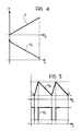
- the voltage between the points a and b of the bridge 10 is indicated V: this voltage, in the thick film sensors of known type, is a linear function of the pressure p detected, as shown qualitatively by the upper graph in Figure 4.
- the voltage V is equal to the difference between the voltages V1 and V2 of the junctions a and b relative to earth.
- the voltages V1 and V2 are applied to the non-inverting inputs of two integrated feedback amplifiers 18, 19.
- the output of the amplifier 18 is connected to the inverting input of the amplifier 19.
- the astable circuit 16 includes in known manner an integrating circuit 29 and a non-inverting threshold comparator 30 with hysteresis, connected together in a closed loop.
- the two resistors 31 and 32 forming a divider between the battery and earth, define the threshold voltage of the comparator 30.
- This latter includes an integrated amplifier 33 with a feedback resistor 34 between the output and the non-inverting input.
- the integrator 29 includes an integrator 29 a capacitor 36 between the output and the inverting input of this amplifier, and a resistor 37. The latter is connected between the output of the comparator 30 and the inverting input of the integrating input 39 to which the output of the integrated amplifier 19 of the processing and amplifying circuit 15 is also connected through the resistor R.
- the integrator 29 outputs in known manner a triangular-wave signal V4 which changes in a manner shown qualitatively in the upper graph of Figure 5 as a function of the time t shown on the abscissa.
- the comparator 30 compares this signal with a threshold, and hence this comparator outputs a square-wave signal V5 which changes as shown qualitatively in the lower graph of Figure 5.
- This signal is supplied to the base of a transistor 40 of npn type through a resistor 41.
- a resistor 42 is connected between the base and the emitter of the transistor 40.
- a resistor 50 is connected between the collector of the transistor 40 and earth.
- the output of the entire device shown in Figure 3 is represented by the collector of the transistor 40.
- the time periods of the rise and fall of the triangular-wave signal V4, linked to the times for charging and discharging the capacitor 36 vary as a function of the amplitude of the signal V3, and the duty cycle of the square-wave signal V5 varies correspondingly. More particularly, in operation, the charging and discharging current of the capacitor 36, which also depends on the value of R, is modulated by the voltage V3. When V3 is equal to the voltage taken from the divider 31, 32, no current flows through R and the circuit 15 is as it were disconnected from the astable circuit 16, which thus oscillates freely in this situation (with a symmetrical waveform).
- the amplification circuit 15 and the astable multivibrator 16 described above operate in a substantially linear manner and enable an average resistance depending on the pressure, and which approximates to the response curve shown in Figure 2, to be obtained at the output of the switching 17.
- the approximation may optionally be improved by the introduction in known manner of non-linear elements into the feedback networks of the integrated amplifiers of circuits 15 and 16.
Landscapes
- Physics & Mathematics (AREA)
- General Physics & Mathematics (AREA)
- Measuring Fluid Pressure (AREA)
- Level Indicators Using A Float (AREA)
Priority Applications (1)
| Application Number | Priority Date | Filing Date | Title |
|---|---|---|---|
| AT86112733T ATE48476T1 (de) | 1985-09-17 | 1986-09-15 | Zwischenschaltung zwischen einem wandler, insbesondere einem dickschichtwiderstanddruckwandler und einem elektrodynamischen instrument und mit einer solchen schaltung ausgeruesteter wandler. |
Applications Claiming Priority (2)
| Application Number | Priority Date | Filing Date | Title |
|---|---|---|---|
| IT6778885 | 1985-09-17 | ||
| IT67788/85A IT1183962B (it) | 1985-09-17 | 1985-09-17 | Circuiti di interfaccia fra un sensore in particolare un sensore di pressione del tipo a film spesso ed uno strumento indicatore elettrodinamico e sensore incorporante tale circuito particolarmente per l'impiego a bordo di autoveicoli |
Publications (2)
| Publication Number | Publication Date |
|---|---|
| EP0216288A1 true EP0216288A1 (fr) | 1987-04-01 |
| EP0216288B1 EP0216288B1 (fr) | 1989-12-06 |
Family
ID=11305296
Family Applications (1)
| Application Number | Title | Priority Date | Filing Date |
|---|---|---|---|
| EP86112733A Expired EP0216288B1 (fr) | 1985-09-17 | 1986-09-15 | Circuit d'interface entre un capteur, en particulier un capteur de pression résistif à couche épaisse et un instrument électrodynamique et capteur incorporant un tel circuit |
Country Status (8)
| Country | Link |
|---|---|
| US (1) | US4748853A (fr) |
| EP (1) | EP0216288B1 (fr) |
| JP (1) | JPS6298229A (fr) |
| AT (1) | ATE48476T1 (fr) |
| DE (1) | DE3667330D1 (fr) |
| ES (1) | ES2005829A6 (fr) |
| IT (1) | IT1183962B (fr) |
| PT (1) | PT83395B (fr) |
Cited By (1)
| Publication number | Priority date | Publication date | Assignee | Title |
|---|---|---|---|---|
| WO1991009276A1 (fr) * | 1989-12-07 | 1991-06-27 | Endress U. Hauser Gmbh U. Co. | Dispositif pour le traitement de signaux d'un detecteur |
Families Citing this family (3)
| Publication number | Priority date | Publication date | Assignee | Title |
|---|---|---|---|---|
| US5031461A (en) * | 1990-02-05 | 1991-07-16 | Motorola, Inc. | Matched pair of sensor and amplifier circuits |
| US7339347B2 (en) * | 2003-08-11 | 2008-03-04 | Reserve Power Cell, Llc | Apparatus and method for reliably supplying electrical energy to an electrical system |
| WO2022198728A1 (fr) * | 2021-03-23 | 2022-09-29 | 微传智能科技(上海)有限公司 | Méthode et système de mesure de la pression des muscles du plancher pelvien féminin |
Citations (2)
| Publication number | Priority date | Publication date | Assignee | Title |
|---|---|---|---|---|
| US3859594A (en) * | 1967-08-21 | 1975-01-07 | Rosemount Inc | Two wire current transmitter responsive to a resistance sensor input signal |
| GB2144857A (en) * | 1983-08-12 | 1985-03-13 | Prutec Ltd | Piezo resistive transducer |
Family Cites Families (1)
| Publication number | Priority date | Publication date | Assignee | Title |
|---|---|---|---|---|
| JPS57177735A (en) * | 1981-04-27 | 1982-11-01 | Toyoda Chuo Kenkyusho Kk | Telemeter type brain nanometer |
-
1985
- 1985-09-17 IT IT67788/85A patent/IT1183962B/it active
-
1986
- 1986-07-16 ES ES8602291A patent/ES2005829A6/es not_active Expired
- 1986-09-15 AT AT86112733T patent/ATE48476T1/de not_active IP Right Cessation
- 1986-09-15 EP EP86112733A patent/EP0216288B1/fr not_active Expired
- 1986-09-15 DE DE8686112733T patent/DE3667330D1/de not_active Expired - Lifetime
- 1986-09-17 US US06/908,538 patent/US4748853A/en not_active Expired - Fee Related
- 1986-09-17 PT PT83395A patent/PT83395B/pt not_active IP Right Cessation
- 1986-09-17 JP JP61217379A patent/JPS6298229A/ja active Pending
Patent Citations (2)
| Publication number | Priority date | Publication date | Assignee | Title |
|---|---|---|---|---|
| US3859594A (en) * | 1967-08-21 | 1975-01-07 | Rosemount Inc | Two wire current transmitter responsive to a resistance sensor input signal |
| GB2144857A (en) * | 1983-08-12 | 1985-03-13 | Prutec Ltd | Piezo resistive transducer |
Non-Patent Citations (2)
| Title |
|---|
| IEEE TRANSACTIONS ON BIO-MEDICAL ENGINEERING, vol. 22, no. 5, September 1975, pages 441-443, New York, US; T.P. GROVER: "Precise voltage to frequency converter to telemetry applications of strain gage pressure transducers" * |
| PATENT ABSTRACTS OF JAPAN, vol. 6, no. 62 (P-111)[940], 21st April 1982; & JP-A-57 004 530 (HITACHI SEISAKUSHO K.K.) 11-01-1982 * |
Cited By (2)
| Publication number | Priority date | Publication date | Assignee | Title |
|---|---|---|---|---|
| WO1991009276A1 (fr) * | 1989-12-07 | 1991-06-27 | Endress U. Hauser Gmbh U. Co. | Dispositif pour le traitement de signaux d'un detecteur |
| US5210501A (en) * | 1989-12-07 | 1993-05-11 | Georg Schneider | Apparatus for processing sensor signals having switch-capacitor structures |
Also Published As
| Publication number | Publication date |
|---|---|
| DE3667330D1 (de) | 1990-01-11 |
| PT83395A (en) | 1986-10-01 |
| IT1183962B (it) | 1987-10-22 |
| ATE48476T1 (de) | 1989-12-15 |
| PT83395B (pt) | 1993-01-29 |
| EP0216288B1 (fr) | 1989-12-06 |
| US4748853A (en) | 1988-06-07 |
| IT8567788A0 (it) | 1985-09-17 |
| ES2005829A6 (es) | 1989-04-01 |
| JPS6298229A (ja) | 1987-05-07 |
Similar Documents
| Publication | Publication Date | Title |
|---|---|---|
| US4703650A (en) | Circuit for the coding of the value of two variables measured in a tire, and device for monitoring tires employing such a circuit | |
| EP0346970B1 (fr) | Circuit pour mesurer la capacité d'une batterie | |
| US5942686A (en) | Ratiometric transducer and method | |
| US3453546A (en) | Telemeter adaptable for implanting in an animal | |
| US4446410A (en) | Control circuit for a solenoid-operated actuator | |
| EP0133695A1 (fr) | Système de capteurs pour mesurer des paramètres | |
| GB1578527A (en) | Apparatus for detecting water in oil | |
| US12416533B2 (en) | Method for monitoring the function of a capacitive pressure measurement cell | |
| EP0404479A1 (fr) | Dispositif de mesure des déplacements | |
| EP0216288B1 (fr) | Circuit d'interface entre un capteur, en particulier un capteur de pression résistif à couche épaisse et un instrument électrodynamique et capteur incorporant un tel circuit | |
| US4560975A (en) | Method of and apparatus for error compensation in electronic analog sensing systems and the like | |
| US5150611A (en) | Flow sensor | |
| EP0078427A2 (fr) | Débitmètre d'air | |
| US6055848A (en) | Air quality measuring device | |
| US6700389B2 (en) | Temperature compensation of an inductive sensor | |
| US4250450A (en) | Detection of engine speed in response to ignition operation | |
| US4310794A (en) | Capacitive probe detection systems | |
| US5144309A (en) | Analog-to-digital converter to be used along with a resistive sensor | |
| EP1502091B1 (fr) | Procede et dispositif de mesure de temperature | |
| US6188226B1 (en) | Electric potential sensor | |
| JP2569595B2 (ja) | センサ信号入力装置の接触抵抗検出装置 | |
| JPH0155419B2 (fr) | ||
| RU2069306C1 (ru) | Индуктивный измеритель перемещения | |
| JP2564961B2 (ja) | 過大入力検出機能付測定器 | |
| JPH089618Y2 (ja) | サーミスタ温度変換回路 |
Legal Events
| Date | Code | Title | Description |
|---|---|---|---|
| PUAI | Public reference made under article 153(3) epc to a published international application that has entered the european phase |
Free format text: ORIGINAL CODE: 0009012 |
|
| AK | Designated contracting states |
Kind code of ref document: A1 Designated state(s): AT BE CH DE FR GB IT LI LU NL SE |
|
| 17P | Request for examination filed |
Effective date: 19870528 |
|
| 17Q | First examination report despatched |
Effective date: 19880531 |
|
| GRAA | (expected) grant |
Free format text: ORIGINAL CODE: 0009210 |
|
| RAP1 | Party data changed (applicant data changed or rights of an application transferred) |
Owner name: MARELLI AUTRONICA S.P.A. |
|
| AK | Designated contracting states |
Kind code of ref document: B1 Designated state(s): AT BE CH DE FR GB IT LI LU NL SE |
|
| REF | Corresponds to: |
Ref document number: 48476 Country of ref document: AT Date of ref document: 19891215 Kind code of ref document: T |
|
| ITF | It: translation for a ep patent filed | ||
| REF | Corresponds to: |
Ref document number: 3667330 Country of ref document: DE Date of ref document: 19900111 |
|
| ET | Fr: translation filed | ||
| PGFP | Annual fee paid to national office [announced via postgrant information from national office to epo] |
Ref country code: AT Payment date: 19900808 Year of fee payment: 5 |
|
| PGFP | Annual fee paid to national office [announced via postgrant information from national office to epo] |
Ref country code: GB Payment date: 19900810 Year of fee payment: 5 |
|
| PGFP | Annual fee paid to national office [announced via postgrant information from national office to epo] |
Ref country code: BE Payment date: 19900814 Year of fee payment: 5 |
|
| PGFP | Annual fee paid to national office [announced via postgrant information from national office to epo] |
Ref country code: CH Payment date: 19900815 Year of fee payment: 5 |
|
| PGFP | Annual fee paid to national office [announced via postgrant information from national office to epo] |
Ref country code: LU Payment date: 19900828 Year of fee payment: 5 |
|
| PGFP | Annual fee paid to national office [announced via postgrant information from national office to epo] |
Ref country code: SE Payment date: 19900829 Year of fee payment: 5 Ref country code: DE Payment date: 19900829 Year of fee payment: 5 |
|
| PGFP | Annual fee paid to national office [announced via postgrant information from national office to epo] |
Ref country code: FR Payment date: 19900928 Year of fee payment: 5 |
|
| PLBE | No opposition filed within time limit |
Free format text: ORIGINAL CODE: 0009261 |
|
| STAA | Information on the status of an ep patent application or granted ep patent |
Free format text: STATUS: NO OPPOSITION FILED WITHIN TIME LIMIT |
|
| ITTA | It: last paid annual fee | ||
| PG25 | Lapsed in a contracting state [announced via postgrant information from national office to epo] |
Ref country code: LU Free format text: LAPSE BECAUSE OF NON-PAYMENT OF DUE FEES Effective date: 19900930 |
|
| PGFP | Annual fee paid to national office [announced via postgrant information from national office to epo] |
Ref country code: NL Payment date: 19900930 Year of fee payment: 5 |
|
| 26N | No opposition filed | ||
| PG25 | Lapsed in a contracting state [announced via postgrant information from national office to epo] |
Ref country code: GB Effective date: 19910915 Ref country code: AT Effective date: 19910915 |
|
| PG25 | Lapsed in a contracting state [announced via postgrant information from national office to epo] |
Ref country code: SE Effective date: 19910916 |
|
| PG25 | Lapsed in a contracting state [announced via postgrant information from national office to epo] |
Ref country code: LI Effective date: 19910930 Ref country code: CH Effective date: 19910930 Ref country code: BE Effective date: 19910930 |
|
| BERE | Be: lapsed |
Owner name: MARELLI AUTRONICA S.P.A. Effective date: 19910930 |
|
| PG25 | Lapsed in a contracting state [announced via postgrant information from national office to epo] |
Ref country code: NL Effective date: 19920401 |
|
| GBPC | Gb: european patent ceased through non-payment of renewal fee | ||
| NLV4 | Nl: lapsed or anulled due to non-payment of the annual fee | ||
| PG25 | Lapsed in a contracting state [announced via postgrant information from national office to epo] |
Ref country code: FR Effective date: 19920529 |
|
| REG | Reference to a national code |
Ref country code: CH Ref legal event code: PL |
|
| PG25 | Lapsed in a contracting state [announced via postgrant information from national office to epo] |
Ref country code: DE Effective date: 19920602 |
|
| REG | Reference to a national code |
Ref country code: FR Ref legal event code: ST |
|
| EUG | Se: european patent has lapsed |
Ref document number: 86112733.0 Effective date: 19920408 |
|
| PG25 | Lapsed in a contracting state [announced via postgrant information from national office to epo] |
Ref country code: IT Free format text: LAPSE BECAUSE OF NON-PAYMENT OF DUE FEES;WARNING: LAPSES OF ITALIAN PATENTS WITH EFFECTIVE DATE BEFORE 2007 MAY HAVE OCCURRED AT ANY TIME BEFORE 2007. THE CORRECT EFFECTIVE DATE MAY BE DIFFERENT FROM THE ONE RECORDED. Effective date: 20050915 |