EP0216293A2 - Verfahren zur Aufzeichnung eines Signals auf einem Magnetband - Google Patents
Verfahren zur Aufzeichnung eines Signals auf einem Magnetband Download PDFInfo
- Publication number
- EP0216293A2 EP0216293A2 EP86112779A EP86112779A EP0216293A2 EP 0216293 A2 EP0216293 A2 EP 0216293A2 EP 86112779 A EP86112779 A EP 86112779A EP 86112779 A EP86112779 A EP 86112779A EP 0216293 A2 EP0216293 A2 EP 0216293A2
- Authority
- EP
- European Patent Office
- Prior art keywords
- track
- control voltage
- block
- magnetic tape
- written
- Prior art date
- Legal status (The legal status is an assumption and is not a legal conclusion. Google has not performed a legal analysis and makes no representation as to the accuracy of the status listed.)
- Granted
Links
- 238000000034 method Methods 0.000 title claims abstract description 16
- 238000001208 nuclear magnetic resonance pulse sequence Methods 0.000 claims description 4
- 230000002123 temporal effect Effects 0.000 claims 1
- 238000010586 diagram Methods 0.000 description 2
- 238000012217 deletion Methods 0.000 description 1
- 230000037430 deletion Effects 0.000 description 1
- 238000011161 development Methods 0.000 description 1
- 230000018109 developmental process Effects 0.000 description 1
- 230000001502 supplementing effect Effects 0.000 description 1
Images
Classifications
-
- G—PHYSICS
- G11—INFORMATION STORAGE
- G11B—INFORMATION STORAGE BASED ON RELATIVE MOVEMENT BETWEEN RECORD CARRIER AND TRANSDUCER
- G11B20/00—Signal processing not specific to the method of recording or reproducing; Circuits therefor
- G11B20/10—Digital recording or reproducing
-
- G—PHYSICS
- G11—INFORMATION STORAGE
- G11B—INFORMATION STORAGE BASED ON RELATIVE MOVEMENT BETWEEN RECORD CARRIER AND TRANSDUCER
- G11B27/00—Editing; Indexing; Addressing; Timing or synchronising; Monitoring; Measuring tape travel
- G11B27/10—Indexing; Addressing; Timing or synchronising; Measuring tape travel
- G11B27/19—Indexing; Addressing; Timing or synchronising; Measuring tape travel by using information detectable on the record carrier
- G11B27/28—Indexing; Addressing; Timing or synchronising; Measuring tape travel by using information detectable on the record carrier by using information signals recorded by the same method as the main recording
- G11B27/30—Indexing; Addressing; Timing or synchronising; Measuring tape travel by using information detectable on the record carrier by using information signals recorded by the same method as the main recording on the same track as the main recording
-
- G—PHYSICS
- G11—INFORMATION STORAGE
- G11B—INFORMATION STORAGE BASED ON RELATIVE MOVEMENT BETWEEN RECORD CARRIER AND TRANSDUCER
- G11B15/00—Driving, starting or stopping record carriers of filamentary or web form; Driving both such record carriers and heads; Guiding such record carriers or containers therefor; Control thereof; Control of operating function
- G11B15/18—Driving; Starting; Stopping; Arrangements for control or regulation thereof
- G11B15/1808—Driving of both record carrier and head
- G11B15/1875—Driving of both record carrier and head adaptations for special effects or editing
-
- G—PHYSICS
- G11—INFORMATION STORAGE
- G11B—INFORMATION STORAGE BASED ON RELATIVE MOVEMENT BETWEEN RECORD CARRIER AND TRANSDUCER
- G11B27/00—Editing; Indexing; Addressing; Timing or synchronising; Monitoring; Measuring tape travel
- G11B27/02—Editing, e.g. varying the order of information signals recorded on, or reproduced from, record carriers
- G11B27/031—Electronic editing of digitised analogue information signals, e.g. audio or video signals
- G11B27/036—Insert-editing
-
- G—PHYSICS
- G11—INFORMATION STORAGE
- G11B—INFORMATION STORAGE BASED ON RELATIVE MOVEMENT BETWEEN RECORD CARRIER AND TRANSDUCER
- G11B5/00—Recording by magnetisation or demagnetisation of a record carrier; Reproducing by magnetic means; Record carriers therefor
- G11B5/008—Recording on, or reproducing or erasing from, magnetic tapes, sheets, e.g. cards, or wires
- G11B5/00813—Recording on, or reproducing or erasing from, magnetic tapes, sheets, e.g. cards, or wires magnetic tapes
- G11B5/00817—Recording on, or reproducing or erasing from, magnetic tapes, sheets, e.g. cards, or wires magnetic tapes on longitudinal tracks only, e.g. for serpentine format recording
- G11B5/00839—Recording on, or reproducing or erasing from, magnetic tapes, sheets, e.g. cards, or wires magnetic tapes on longitudinal tracks only, e.g. for serpentine format recording using cyclically driven heads providing segmented tracks
-
- G—PHYSICS
- G11—INFORMATION STORAGE
- G11B—INFORMATION STORAGE BASED ON RELATIVE MOVEMENT BETWEEN RECORD CARRIER AND TRANSDUCER
- G11B2220/00—Record carriers by type
- G11B2220/90—Tape-like record carriers
-
- G—PHYSICS
- G11—INFORMATION STORAGE
- G11B—INFORMATION STORAGE BASED ON RELATIVE MOVEMENT BETWEEN RECORD CARRIER AND TRANSDUCER
- G11B27/00—Editing; Indexing; Addressing; Timing or synchronising; Monitoring; Measuring tape travel
- G11B27/02—Editing, e.g. varying the order of information signals recorded on, or reproduced from, record carriers
- G11B27/031—Electronic editing of digitised analogue information signals, e.g. audio or video signals
- G11B27/032—Electronic editing of digitised analogue information signals, e.g. audio or video signals on tapes
Definitions
- the invention relates to a method for recording a signal on a tape-shaped recording medium, in particular for a digital signal on a magnetic tape, in which track segments which are successive in time and which are short in relation to the length of the carrier lie next to one another, the track segments running approximately parallel to the edge of the carrier and lie next to one another in the transverse direction to the carrier edge such that the boundary lines of the blocks of track sections formed are directed perpendicularly or approximately perpendicularly to the carrier edge.
- This so-called insert method has e.g. the purpose of correcting a faulty record, replacing a record with another record or supplementing an existing record e.g. through a preamble or introduction.
- the invention has for its object to develop the method described so that when rewriting a block or several consecutive blocks, the newly written tracks take up the required length on the tape.
- the solution according to the invention thus ensures that when a block is rewritten, the geometric length of the track written on the magnetic tape is approximately equal to the geometric length of the previously written track which was deleted when rewritten.
- the rewritten block or several successive rewritten blocks then desirably have practically the same track position and track length as the blocks previously written on the tape.
- the gap formed by the deleted blocks is therefore filled in exactly by the newly written blocks, without any annoying gaps or overlaps occurring.
- the beginning of a newly written track is based on the end of the corresponding track of the previously written block and the end of a newly written track on the beginning of the track of the following block. The beginning and end of the track are marked by start and end impulses.
- the control voltage can affect the longitudinal speed of the magnetic tape, i.e. the advance of the magnetic tape in the longitudinal direction, since this speed has an influence on the length of the 'written track'. If e.g. the direction of the longitudinal speed of the magnetic tape and the rotational speed of the head wheel relative to the tape in the wrap area are opposite, an increase in the longitudinal speed causes an increase in the length of the written track on the tape. Therefore, the control voltage can act on the drive for the longitudinal speed, the so-called capstan.
- the control voltage can also affect the speed of rotation of the top wheel, since this also affects the length of the track written. If the speed of rotation increases, the length of the written track becomes longer with the same signal duration.
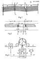
- FIG. 1 shows the magnetic tape 1, on which blocks B1, B2, B3 .... in the longitudinal direction of the tape 1 are written one behind the other in matrix-like fashion, each with tracks S1, S2, S3, S4 .... running parallel to one another.
- the tracks S are marked by start pulses 7 and end pulses 8.
- the dashed lines L denote dividing lines between two successive blocks.
- the tape 1 is described in the manner described with the blocks B.
- the tracks S of block B2 are to be rewritten by a write operation together with an erase operation.
- the start of track S1 of block B2 is oriented to the end of track S1 of block B1, as is the case with a normal write operation.
- the track S1 of the block B2 has a geometrical length which is too short, that is to say the end pulse 8 is too early relative to the dividing line L between the blocks B2 and B3.
- the length of track S2 is increased by the control voltage obtained therefrom, so that the final pulse 8 is already later in this track.
- the length of the track in the track S3 is increased by the control to such an extent that the end pulse 8 is in the correct position with respect to the dividing line L as in block B1 and thus the track S3 has its target length. All other tracks S of block B2 are then written with the correct geometric length.
- the track sl from the block B2 at the point sl from the end pulse 8 with the magnetic head K1 in accordance with FIG. Fig. 3 generates the pulse A, which thus indicates the actual end of the newly written track sl.
- the written track sl is too short.
- the target end of the track is s2.
- the head K1 previously used for writing the track sl is switched over to reading. Since the head Kl acc. 3 also remains in tape contact beyond the end of block B2, the head K1 reads the initial pulse 7 at the location s3 of the block B3 originating from the existing record and then generates the pulse B at the location s3.
- the distance ⁇ t is therefore a measure of the deviation of the position of the end of the track sl in block B2 from the target position.
- the control voltage for influencing the length of the tracks S of the block B2 is obtained from this deviation ⁇ t.
- Fig. 3 shows the magnetic tape 1, the rotating head drum 11 with four heads K1, K2, K3, K4 and the drive 2 for the longitudinal speed of the tape 1.
- the control unit 3 controls the writing and reading processes with the heads K1 to K4 and generates the pulses A and B acc. Fig. 2.
- the pulses A and B are compared with each other in the comparison stage 4.
- Control voltages Url and Ur2 are obtained from the time deviation ⁇ t.
- the control voltage Url acts on the drive 2 and increases the longitudinal speed V of the magnetic tape 1 to increase the length of the track written.
- the control voltage Ur2 acts on the motor 5 and increases the speed of rotation of the top wheel 11 also to increase the length of the written track.
- the two regulations with Url and Ur2 can also be applied individually.
Landscapes
- Engineering & Computer Science (AREA)
- Signal Processing (AREA)
- Multimedia (AREA)
- Signal Processing For Digital Recording And Reproducing (AREA)
- Digital Magnetic Recording (AREA)
- Recording Or Reproducing By Magnetic Means (AREA)
- Management Or Editing Of Information On Record Carriers (AREA)
- Television Signal Processing For Recording (AREA)
Abstract
Description
- Die Erfindung betrifft ein Verfahren zur Aufzeichnung eines Signals auf einem bandförmigen Aufzeichnungsträger, insbesondere für ein Digitalsignal auf einem Magnetband, bei dem jeweils zeitlich aufeinanderfolgende, gegenüber der Länge des Trägers kurze Spurabschnitte auf dem Träger nebeneinander liegen, wobei die.Spurabschnitte etwa parallel zur Trägerkante verlaufen und in Querrichtung zur Trägerkante derart nebeneinander liegen, daß die Begrenzungslinien der gebildeten Blöcke von Spurabschnitten senkrecht oder annähernd senkrecht zur Trägerkante gerichtet sind.
- Bei einem derartigen Verfahren bestehen der Wunsch und die Möglichkeit, einzelne Blöcke oder mehrere aufeinanderfolgende Blöcke auf einem beschriebenen Band gezielt neu zu schreiben und dabei die bisher beschriebenen Blöcke löschen. Dieses sogenannte Insert-Verfahren hat z.B. den Zweck, eine fehlerhafte Aufzeichnung zu korrigieren, eine Aufzeichnung durch eine andere Aufzeichnung zu ersetzen oder eine bereits vorhandene Aufzeichnung zu ergänzen z.B. durch einen Vorspann oder Einleitung.
- Da die aufeinanderfolgenden Blöcke in Längsrichtung des Magnetbandes hintereinander liegen und ihre Anfänge und Enden jeweils durch Kennsignale markiert sind, ist ein derartiges gezieltes Neuschreiben einer ganzen Anzahl von Blöcken grundsätzlich möglich. Durch Toleranzen bei verschiedenen Parametern wie Z.B. der Dehnung des Bandes, der Längsgeschwindigkeit des Magnetbandes und der Rotationsgeschwindigkeit der Kopftrommel ist jedoch nicht gewährleistet, daß die neu geschriebenen Spuren eines Blockes die gleiche geometrische Länge auf dem Band wie die Spuren des ursprünglich geschriebenen Blockes haben. Dann kann der Fall eintreten, daß ein neu geschriebener Block in die durch das Löschen des ursprünglich geschriebenen Blockes gebildete Lücke nicht hineinpaßt oder diese nicht voll ausfüllt. In beiden Fällen kann es zu Synchronisierstörungen bei der Wiedergabe oder sogar zu einer unerwünschten Löschung von Signalteilen eines Blockes kommen.
- Der Erfindung liegt die Aufgabe zugrunde, das beschriebene Verfahren so weiterzubilden, daß beim Neuschreiben eines Blockes oder mehrerer aufeinander folgender Blöcke die neu geschriebenen Spuren die erforderliche Länge auf dem Band einnehmen.
- Diese Aufgabe wird durch die im Anspruch 1 beschriebene Erfindung gelöst. Vorteilhafte Weiterbildungen der Erfindung sind in den Unteransprüchen beschrieben.
- Durch die erfindungsgemäße Lösung wird also erreicht, daß beim Neuschreiben eines Blockes die geometrische Länge der auf dem Magnetband geschriebenen Spur etwa gleich der geometrischen Länge der vorher geschriebenen, beim Neuschreiben gelöschten Spur ist. Der neu geschriebene Block oder mehrere aufeinanderfolgende neu geschriebene Blöcke haben dann in erwünschter Weise praktisch die gleich Spurlage und Spurlänge wie die vorher auf dem Band geschriebenen Blöcke. Die durch die gelöschten Blöcke gebildete Lücke wird also durch die neu geschriebenen Blöcke genau ausgefüllt, ohne daß dabei störende Lücken oder Überschneidungen auftreten. Der Anfang einer neu geschriebenen Spur orientiert sich dabei an dem Ende der entsprechenden Spur des vorher geschriebenen Blockes und das Ende einer neu geschriebenen Spur an dem Anfang der Spur des folgenden Blockes. Die Spuranfänge und Spurenden sind dabei jeweils durch Anfangsimpulse und Endimpulse markiert.
- Zum Ausgleich von Toleranzen ist es dabei notwendigf die geometrische Länge der auf dem Band neu geschriebenen Spur mit - einer Regelspannung zu beeinflussen. Hierfür gibt es verschiedene Möglichkeiten.
- Die Regelspannung kann auf die Längsgeschwindigkeit des Magnetbandes, also den Vorschub des Magnetbandes in Längsrichtung, einwirken, da diese Geschwindigkeit Einfluß auf die Länge der` geschriebenen Spur hat. Wenn z.B. die Richtung der Längsgeschwindigkeit des Magnetbandes und die Rotationsgeschwindigkeit des Kopfrades relativ zum Band im Umschlingungsbereich entgegengesetzt gerichtet sind, bewirkt eine Vergrößerung der Längsgeschwindigkeit eine Vergrößerung der Länge der geschriebenen Spur auf dem Band. Daher kann die Regelspannung auf den Antrieb für die Längsgeschwindigkeit, den sogenannten Capstan, einwirken.
- Die Regelspannung kann auch auf die Rotationsgeschwindigkeit des Kopfrades einwirken, da diese ebenfalls auf die Länge der geschriebenen Spur eingeht. Bei einer Erhöhung der Rotationsgeschwindigkeit wird die Länge der geschriebenen Spur bei gleichbleibender Signaldauer länger.
- Es ist möglich, mit der Regelspannung die Dauer des geschriebenen Signales zu beeinflussen, so daß dann der jeweils geschriebene Kopf für eine längere Zeit mit dem neu geschriebenen Signal gesteuert wird und somit die Länge der Spur vergrößert wird. Eine derartige Änderung der Dauer eines Signals ist dadurch möglich, daß das Signal mit einer ersten Taktimpulsfolge in einen Speicher eingelesen und mit einer zweiten, von der Regelspannung beeinflußten Taktimpulsfolge aus dem Speicher ausgelesen wird. Die Wirkungsweise eines derartigen Speichers, der auch als FIFO (first-in / firstout) bezeichnet wird, ist näher beschrieben in der älteren Patentanmeldung P 36 26 017. Die beschriebenen Möglichkeiten zur Beeinflussung der geometrischen Länge der neu geschriebenen Spur können je für sich allein oder auch in verschiedenen Kombinationen additiv zur Regelung der Spurlänge verwendet werden.
- Die Erfindung wird im folgenden anhand der Zeichnungen erläutert. Darin zeigen
- Fig. 1 das Magnetband mit Spuren von drei Blöcken, r.,von denen einer neu geschrieben wird,
- Fig. 2 ein Prinzipschaltbild zur Erläuterung der Erzeugung der Regelspannung und
- Fig. 3 ein Blockschaltbild zur Durchführung des erfindungsgemäßen Verfahrens.
- Fig. 1 zeigt das Magnetband 1, auf dem in Längsrichtung des Bandes 1 hintereinander matrixartig Blöcke B1, B2, B3.... jeweils mit parallel zueinander verlaufenden Spuren S1, S2, S3, S4.... geschrieben sind. Die Spuren S sind durch Anfangsimpulse 7 und Endimpulse 8 markiert. Die gestrichelten Linien L bezeichnen Trennlinien jeweils zwischen zwei aufeinanderfolgenden Blöcken. Das Band 1 ist in der beschriebenen Weise mit den Blöcken B beschrieben. Die Spuren S des Blockes B2 sollen durch einen Schreibvorgang zusammen mit einem Löschvorgang neu geschrieben werden. Der Anfang der Spur S1 des Blockes B2 orientiert sich wie bei einem üblichen Schreibvorgang an dem Ende der Spur S1 des Blockes B1. In Fig. 1 ist angenommen, daß durch den neuen Schreibvorgang die Spur S1 des Blockes B2 eine zu kurze geometrische Länge hat, der Endimpuls 8 also zu früh relativ zur Trennlinie L zwischen den Blöcken B2 und B3 liegt. Durch die daraus gewonnene Regelspannung wird die Länge der Spur S2 vergrößert, so daß bei dieser Spur der Endimpuls 8 bereits später liegt. Es ist angenommen, daß in der Spur S3 durch die Regelung die Länge der Spur soweit vergrößert ist, daß der Endimpuls 8 die richtige Lage zur Trennlinie L wie im Block B1 und damit die Spur S3 ihre Soll-Länge hat. Alle übrigen Spuren S des Blockes B2 werden dann mit der richtigen geometrischen Länge geschrieben.
- Gemäß Fig. 2 wird am Ende des Schreibvorgangs der Spur sl vom Block B2 an der Stelle sl aus dem Endimpuls 8 mit dem Magnetkopf K1 gem. Fig. 3 der Impuls A erzeugt, der somit das Ist-Ende der neu geschriebenen Spur sl anzeigt. Die geschriebene Spur sl ist zu kurz. Das soll-Ende der Spur liegt bei s2. Gleichzeitig wird der bisher zum Schreiben der Spur sl benutzte Kopf K1 auf Lesen umgeschaltet. Da der Kopf Kl gem. Fig. 3 auch über das Ende des Blockes B2 hinaus in Bandkontakt bleibt, liest der Kopf K1 an der Stelle s3 den Anfangsimpuls 7 des aus der vorhandenen Aufzeichnung stammenden Blockes B3 und erzeugt daraufhin den Impuls B an der Stelle s3. Der Abstand Δt ist also ein Maß für die Abweichung der Lage des Endes der Spur sl im Block B2 von der Sollage. Aus dieser Abweichung Δt wird die Regelspannung zur Beeinflussung der Länge der Spuren S des Blockes B2 gewonnen.
- Fig. 3 zeigt das Magnetband 1, die rotierende Kopftrommel 11 mit vier Köpfen Kl, K2, K3,K4 und dem Antrieb 2 für die Längsgeschwindigkeit des Bandes 1. Die Steuereinheit 3 steuert die Schreib- und Lesevorgänge mit den Köpfen K1 bis K4 und erzeugt die Impulse A und B gem. Fig. 2. Die Impulse A und B werden in der Vergleichsstufe 4 mit einander verglichen. Aus der zeitlichen Abweichung Δt werden Regelspannungen Url und Ur2 gewonnen. Die Regelspannung Url wirkt auf den Antrieb 2 ein und erhöht die Längsgeschwindigkeit V des Magnetbandes 1 zur Vergrößerung der Länge der geschriebenen Spur. Die Regelspannung Ur2 wirkt auf den Motor 5 ein und vergrößert die Rotationsgeschwindigkeit des Kopfrades 11 ebenfalls zur Vergrößerung der Länge der geschriebenen Spur.
- Die beiden Regelungen mit Url und Ur2 können auch je für sich angewendet werden.
- Wenn die geschriebene Spur sl des Blockes B2 Uberlänge hat, kann der Fall eintreten, daß der Anfangsimpuls 7 der Spur sl des Blockes B3 gelöscht wird und somit der Anfang dieser Spur wegen des Fehlens des Anfangsimpulses 7 nicht mehr erkannt werden kann. Deshalb ist es zweckmäßig, die Antriebswerte so auszulegen, daß ohne Einsatz der Regelung die neu geschriebenen Spuren eines Blockes grundsätzlich zu kurz sind und die Regelung immer im Sinne einer Vergrößerung der Spurlänge bis auf den Sollwert wirkt. Dann wird sichergestellt, daß das Ende einer neu geschriebenen Spur jeweils die Trennlinie L nicht überschreiten kann.
Claims (6)
Priority Applications (1)
| Application Number | Priority Date | Filing Date | Title |
|---|---|---|---|
| AT86112779T ATE70658T1 (de) | 1985-09-21 | 1986-09-16 | Verfahren zur aufzeichnung eines signals auf einem magnetband. |
Applications Claiming Priority (2)
| Application Number | Priority Date | Filing Date | Title |
|---|---|---|---|
| DE3533761 | 1985-09-21 | ||
| DE19853533761 DE3533761A1 (de) | 1985-09-21 | 1985-09-21 | Verfahren zur aufzeichnung eines signals auf einem magnetband |
Publications (3)
| Publication Number | Publication Date |
|---|---|
| EP0216293A2 true EP0216293A2 (de) | 1987-04-01 |
| EP0216293A3 EP0216293A3 (en) | 1989-02-01 |
| EP0216293B1 EP0216293B1 (de) | 1991-12-18 |
Family
ID=6281614
Family Applications (1)
| Application Number | Title | Priority Date | Filing Date |
|---|---|---|---|
| EP86112779A Expired - Lifetime EP0216293B1 (de) | 1985-09-21 | 1986-09-16 | Verfahren zur Aufzeichnung eines Signals auf einem Magnetband |
Country Status (5)
| Country | Link |
|---|---|
| EP (1) | EP0216293B1 (de) |
| JP (1) | JPS62119782A (de) |
| KR (1) | KR870003494A (de) |
| AT (1) | ATE70658T1 (de) |
| DE (2) | DE3533761A1 (de) |
Cited By (1)
| Publication number | Priority date | Publication date | Assignee | Title |
|---|---|---|---|---|
| EP0413288A3 (en) * | 1989-08-17 | 1992-09-02 | Nokia Unterhaltungselektronik (Deutschland) Gmbh | Video recorder with automatic search mode |
Families Citing this family (2)
| Publication number | Priority date | Publication date | Assignee | Title |
|---|---|---|---|---|
| JPS648575A (en) * | 1987-06-30 | 1989-01-12 | Toshiba Corp | Video recording and reproducing device |
| DE4119625C1 (de) * | 1991-06-14 | 1992-09-10 | Grundig E.M.V. Elektro-Mechanische Versuchsanstalt Max Grundig Hollaend. Stiftung & Co Kg, 8510 Fuerth, De |
Family Cites Families (4)
| Publication number | Priority date | Publication date | Assignee | Title |
|---|---|---|---|---|
| DE1449831B2 (de) * | 1963-12-02 | 1975-02-20 | Iwasaki Tsushinki K.K. | Einrichtung zur Bildung von blockweise gebündelten Signalgruppen |
| DE2461868C3 (de) * | 1974-12-30 | 1980-03-27 | Sycor, Inc., Ann Arbor, Mich. (V.St.A.) | Verfahren und Aufzeichnungsgerät zum Überschreiben von Aufzeichnungsblöcken |
| GB8323112D0 (en) * | 1983-08-26 | 1983-09-28 | British Broadcasting Corp | Recording of digital data |
| EP0197333B1 (de) * | 1985-03-16 | 1989-12-13 | Deutsche Thomson-Brandt GmbH | Verfahren zur Aufzeichnung eines Signals auf einen bandförmigen Aufzeichnungsträger |
-
1985
- 1985-09-21 DE DE19853533761 patent/DE3533761A1/de not_active Withdrawn
-
1986
- 1986-09-11 KR KR1019860007640A patent/KR870003494A/ko not_active Abandoned
- 1986-09-16 AT AT86112779T patent/ATE70658T1/de not_active IP Right Cessation
- 1986-09-16 EP EP86112779A patent/EP0216293B1/de not_active Expired - Lifetime
- 1986-09-16 DE DE8686112779T patent/DE3682992D1/de not_active Expired - Fee Related
- 1986-09-22 JP JP61222260A patent/JPS62119782A/ja active Pending
Cited By (1)
| Publication number | Priority date | Publication date | Assignee | Title |
|---|---|---|---|---|
| EP0413288A3 (en) * | 1989-08-17 | 1992-09-02 | Nokia Unterhaltungselektronik (Deutschland) Gmbh | Video recorder with automatic search mode |
Also Published As
| Publication number | Publication date |
|---|---|
| JPS62119782A (ja) | 1987-06-01 |
| ATE70658T1 (de) | 1992-01-15 |
| KR870003494A (ko) | 1987-04-17 |
| DE3682992D1 (de) | 1992-01-30 |
| EP0216293A3 (en) | 1989-02-01 |
| DE3533761A1 (de) | 1987-03-26 |
| EP0216293B1 (de) | 1991-12-18 |
Similar Documents
| Publication | Publication Date | Title |
|---|---|---|
| DE3046722C2 (de) | ||
| DE2702971A1 (de) | Verfahren zur aufzeichnung von haupt- und zugeordneten hilfssignalen auf einem aufzeichnungsmedium und nach dem verfahren hergestellter aufzeichnungstraeger | |
| DE2659659C3 (de) | Anordnung zum elektronischen Schneiden bei Videomagnetbandspeichern | |
| DE3045541A1 (de) | Verfahren und anordnung zur wiedergabe von auf einenaufzeichnungstraeger in einzelnen spuren aufgezeichneten videosignalen | |
| DE69920868T2 (de) | Spurfolge-servosignalmusterschreibmethode für magnetplattenvorrichtung | |
| DE3245509A1 (de) | Drehbare kopfeinheit | |
| AT397897B (de) | Verfahren zur aufzeichnung von einem videosignal entsprechenden digitalen daten | |
| EP0216293B1 (de) | Verfahren zur Aufzeichnung eines Signals auf einem Magnetband | |
| DE68915028T2 (de) | Magnetisches Aufzeichnungs- und Wiedergabegerät. | |
| DE3044624C2 (de) | ||
| DE69020594T2 (de) | Gerät zum Aufzeichnen und Wiedergeben von Signalen. | |
| DE69119613T2 (de) | Aufnahme- und Wiedergabegerät mit Editierfunktion | |
| DE2506853A1 (de) | Magnetisches aufzeichnungs- und wiedergabesystem | |
| DE2055538A1 (de) | Anordnung zum Auffinden auf Magnet band aufgezeichneter Information | |
| DE3107733C2 (de) | ||
| DE3044623A1 (de) | System zur aufzeichnung und/oder wiedergabe von digitalen signalen auf einen bandfoermigen traeger | |
| DE2432982A1 (de) | Mehrspur-aufzeichnungskopf | |
| EP0010716A1 (de) | Verfahren und Anordnung zum Verändern von Videoaufzeichnungen mit oder ohne Audioinformation in Videoaufzeichnungs-/Wiedergabesystemen, insbesondere Magnet-Aufzeichnungs-/Wiedergabesystemen | |
| DE1918555A1 (de) | Verfahren zum Aufzeichnen von Informationen auf ein Magnetband | |
| DE3517380A1 (de) | Verfahren zur spurfindung | |
| DE1947741A1 (de) | Verfahren zur Aufzeichnung und Wiedergabe von Fernsehsignalen | |
| DE3239307C2 (de) | ||
| DE3711951A1 (de) | Videorecorder mit standard- und langzeitbetrieb | |
| DE3541272A1 (de) | Magnetbandgeraet | |
| DE2654577A1 (de) | Einrichtung mit einem einspur-magnetkopf |
Legal Events
| Date | Code | Title | Description |
|---|---|---|---|
| PUAI | Public reference made under article 153(3) epc to a published international application that has entered the european phase |
Free format text: ORIGINAL CODE: 0009012 |
|
| AK | Designated contracting states |
Kind code of ref document: A2 Designated state(s): AT BE CH DE FR GB IT LI LU NL SE |
|
| RIN1 | Information on inventor provided before grant (corrected) |
Inventor name: PETERS, HARTMUT, DIPL.-ING. Inventor name: SCHAEFER, RALF-DIETER, DIPL.-ING. Inventor name: HABBEN, DIETER, DIPL.-ING. Inventor name: HARTNACK, WOLFGANG, DIPL.-ING. Inventor name: OBERJATZAS, GUENTER, DIPL.-ING. Inventor name: KEESEN, WERNER, DR.-ING. |
|
| PUAL | Search report despatched |
Free format text: ORIGINAL CODE: 0009013 |
|
| RHK1 | Main classification (correction) |
Ipc: G11B 27/02 |
|
| AK | Designated contracting states |
Kind code of ref document: A3 Designated state(s): AT BE CH DE FR GB IT LI LU NL SE |
|
| 17P | Request for examination filed |
Effective date: 19890706 |
|
| 17Q | First examination report despatched |
Effective date: 19900905 |
|
| GRAA | (expected) grant |
Free format text: ORIGINAL CODE: 0009210 |
|
| AK | Designated contracting states |
Kind code of ref document: B1 Designated state(s): AT BE CH DE FR GB IT LI LU NL SE |
|
| REF | Corresponds to: |
Ref document number: 70658 Country of ref document: AT Date of ref document: 19920115 Kind code of ref document: T |
|
| GBT | Gb: translation of ep patent filed (gb section 77(6)(a)/1977) | ||
| ITF | It: translation for a ep patent filed | ||
| REF | Corresponds to: |
Ref document number: 3682992 Country of ref document: DE Date of ref document: 19920130 |
|
| ET | Fr: translation filed | ||
| PGFP | Annual fee paid to national office [announced via postgrant information from national office to epo] |
Ref country code: LU Payment date: 19920820 Year of fee payment: 7 |
|
| PGFP | Annual fee paid to national office [announced via postgrant information from national office to epo] |
Ref country code: GB Payment date: 19920902 Year of fee payment: 7 |
|
| PGFP | Annual fee paid to national office [announced via postgrant information from national office to epo] |
Ref country code: AT Payment date: 19920910 Year of fee payment: 7 |
|
| PG25 | Lapsed in a contracting state [announced via postgrant information from national office to epo] |
Ref country code: SE Effective date: 19920917 |
|
| PG25 | Lapsed in a contracting state [announced via postgrant information from national office to epo] |
Ref country code: LI Effective date: 19920930 Ref country code: CH Effective date: 19920930 Ref country code: BE Effective date: 19920930 |
|
| PGFP | Annual fee paid to national office [announced via postgrant information from national office to epo] |
Ref country code: NL Payment date: 19920930 Year of fee payment: 7 |
|
| PLBE | No opposition filed within time limit |
Free format text: ORIGINAL CODE: 0009261 |
|
| STAA | Information on the status of an ep patent application or granted ep patent |
Free format text: STATUS: NO OPPOSITION FILED WITHIN TIME LIMIT |
|
| 26N | No opposition filed | ||
| EPTA | Lu: last paid annual fee | ||
| BERE | Be: lapsed |
Owner name: DEUTSCHE THOMSON-BRANDT G.M.B.H. Effective date: 19920930 |
|
| PG25 | Lapsed in a contracting state [announced via postgrant information from national office to epo] |
Ref country code: FR Effective date: 19930528 |
|
| REG | Reference to a national code |
Ref country code: CH Ref legal event code: PL |
|
| PG25 | Lapsed in a contracting state [announced via postgrant information from national office to epo] |
Ref country code: DE Effective date: 19930602 |
|
| REG | Reference to a national code |
Ref country code: FR Ref legal event code: ST |
|
| PG25 | Lapsed in a contracting state [announced via postgrant information from national office to epo] |
Ref country code: LU Free format text: LAPSE BECAUSE OF NON-PAYMENT OF DUE FEES Effective date: 19930916 Ref country code: GB Effective date: 19930916 Ref country code: AT Effective date: 19930916 |
|
| PG25 | Lapsed in a contracting state [announced via postgrant information from national office to epo] |
Ref country code: NL Effective date: 19940401 |
|
| GBPC | Gb: european patent ceased through non-payment of renewal fee |
Effective date: 19930916 |
|
| NLV4 | Nl: lapsed or anulled due to non-payment of the annual fee | ||
| EUG | Se: european patent has lapsed |
Ref document number: 86112779.3 Effective date: 19930406 |
|
| PG25 | Lapsed in a contracting state [announced via postgrant information from national office to epo] |
Ref country code: IT Free format text: LAPSE BECAUSE OF NON-PAYMENT OF DUE FEES Effective date: 20050916 |