EP0216404A1 - Apparat zur Bilderzeugung mittels magnetischer Resonanz mit homogenisierenden magnetischen Elementen - Google Patents
Apparat zur Bilderzeugung mittels magnetischer Resonanz mit homogenisierenden magnetischen Elementen Download PDFInfo
- Publication number
- EP0216404A1 EP0216404A1 EP86201372A EP86201372A EP0216404A1 EP 0216404 A1 EP0216404 A1 EP 0216404A1 EP 86201372 A EP86201372 A EP 86201372A EP 86201372 A EP86201372 A EP 86201372A EP 0216404 A1 EP0216404 A1 EP 0216404A1
- Authority
- EP
- European Patent Office
- Prior art keywords
- magnetic
- imaging apparatus
- resonance imaging
- field
- magnetic resonance
- Prior art date
- Legal status (The legal status is an assumption and is not a legal conclusion. Google has not performed a legal analysis and makes no representation as to the accuracy of the status listed.)
- Granted
Links
Images
Classifications
-
- G—PHYSICS
- G01—MEASURING; TESTING
- G01R—MEASURING ELECTRIC VARIABLES; MEASURING MAGNETIC VARIABLES
- G01R33/00—Arrangements or instruments for measuring magnetic variables
- G01R33/20—Arrangements or instruments for measuring magnetic variables involving magnetic resonance
- G01R33/28—Details of apparatus provided for in groups G01R33/44 - G01R33/64
- G01R33/38—Systems for generation, homogenisation or stabilisation of the main or gradient magnetic field
- G01R33/387—Compensation of inhomogeneities
- G01R33/3873—Compensation of inhomogeneities using ferromagnetic bodies ; Passive shimming
Definitions
- the invention relates to a magnetic resonance imaging apparatus which includes a magnetic system for generating a steady magnetic field in a measurement space situated within the magnet system, and also relates to a method of designing such an apparatus.
- the steady magnetic field in a measurement space within the magnet system has a high spatial homogeneity.
- the cited article provides a solution for correction of lower-order errors which are understood to be errors up to the fourth order.
- errors may be caused by magnetic disturbances from the environment, manufacturing tolerances, errors due to irregularities in the turns of the coils, non-optimum positioning of the coils and the like. It is assumed that any error up to the fourth order, which means in practice the second and the fourth order errors for zonal errors, is separately reduced to an as low as possible value.
- a magnetic resonance imaging apparatus of the kind set forth in accordance with the invention is characterized in that within the magnet system there is provided a magnetic material which increases the spatial field homogeneity also for errors beyond the fourth order.
- the ferromagnetic elements are preferably formed by pairs of rings which are arranged each time symmetrically with respect to the centre of a coil former.
- the rings can be sub-divided into a plurality of sector arcs by means of azimuthal interruptions.
- the rings or ring segments may be accomodated, for example in recesses in a carrier for gradient coils which is customarily arranged within the magnet system for the steady field.
- the ferromagnetic material of each ring or ring segment may be composed of a stack of wires, but may also be shaped as a band or a strip.
- a preferred embodiment utilizes three pairs of ring segments of ferromagnetic material which are symmetrically arranged with respect to the central plane of the magnet system, viewed in the axial direction.
- a magnet system for generating a steady magnetic field for an apparatus in accordance with the invention is notably constructed so as to be comparatively short. This results in a patient-friendly apparatus. As a result of the compensation of the individual error contributions, the resultant field will still be homogeneous to a high degree.
- the compensation of higher-order fields utilizes, for example a method where the resultant of the higher-order contributions to be dealt with is minimized by the axial position, the width and the thickness of ring pairs of ferromagnetic material.
- the subsidiary conditions notably the axial dimension of the coil system, can be chosen with a higher degree of freedom, because the contributions of the higher-order errors in the field can still be compensated for at a later stage. An optimum compromise can thus result in a geometrically more attractive magnet system.
- the ferromagnetic material can be simply accommodated in a cooled space for the superconducting coils; this may be the helium space as well as a jacket space filled, for example with liquid nitrogen. Using an adapted design, the functions of heat shield and error correction can thus be combined. When accommodated in a cooled space, the ferromagnetic material need be cooled only once and will not form an additional heat leak because no external connections are required. The increased thermal capacity or rather cold reserve can often be used to good advantage.
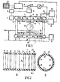
- a magnetic resonance imaging apparatus as shown in Figure 1 includes a magnet system 2 for generating a steady, uniform magnetic field H, a magnet system 4 for generating magnetic gradient fields, and power supply sources 6 and 8 for the magnet systems 2 and 4, respectively.
- An r.f. magnet coil 10 serves to generate an r.f. magnetic alternating field; to this end it is connected to an r.f. source 12.
- the r.f. coil 10 is then connected to a signal amplifier 14.
- the signal amplifier 14 is connected to a phase-sensitive rectifier 16 which is connected to a central control device 18.
- the central control device 18 also controls a modulator 20 for the r.f.
- a cooling device 26 which includes cooling ducts 27.
- Such a cooling device may be constructed, for example as a water cooling system for resistance coils or as liquid helium cooling system for superconducting magnet coils for a high field intensity.
- the transmitter coil 10 arranged within the magnet systems 2 and 4 encloses a measurement space 28 which is sufficiently large to accomodate patients to be examined in the case of a medical diagnostic apparatus.
- the r.f. coil 10 is assumed to combine the functions of transmitter coil and measurement coil. However, for both functions use can also be made of different coils, for example surface coils being used as the measurement coils.
- the coil system 2 for the steady field is in this case formed by six isoradial coils 29 which are accomodated as superconducting coils in a dewar vessel 30 for liquid helium which can be introduced therein from the cooling device 26.
- the cooling device may be simply a storage device for liquid helium as well as a helium liquefier. In the latter case the helium evaporated in the dewar vessel is continuously cooled again so that a closed cooling system is obtained.
- a helium dewar vessel there is arranged a conventional jacket which is filled with, for example liquid nitrogen.
- a gradient coil holder 32 supporting the gradient coils 4 is arranged inside the coils for the main field, and hence inside the dewar vessel in a customary manner.
- rings 34 of, for example ferromagnetic material are mounted in the gradient coil holder 32.
- the rings form (except for specific magnet design) ring pairs which are always symmetrically situated with respect to an axial symmetry plane 36 of the magnet system. Using very practical isoradial pairs of rings, the contribution to the homogenizing of the steady magnetic field H in the measurement space 28 is thus determined by the position of the pairs of rings with respect to the symmetry plane 36, by the width of the pairs of rings and by the amount of ferromagnetic material per pair.
- All rings are rotationally symmetrical, except for specific magnet designs, so that they contain a uniform quantity of magnetic material, measured along the circumference.
- a magnet design can be realized in accordance with the invention, for example as follows.
- Subsidiary conditions to be satisfied are the miniumum requirements to be imposed as regards the diagnostic images to be realized by means of the apparatus.
- the requirements to be imposed on the homogeneity of the steady magnetic field whereto the present description is restricted should be formulated.
- technological, structural and geometrical limitations are technological, structural and geometrical limitations.
- the non-corrected field may also be produced, for example by a coil design which is not completely isoradial. More or less itteratively a minimum permissible length can thus be stepwise determined for the magnet system.
- a coil is in principle optimally compensated for only for a fixed field intensity.
- the magnet is to be used, for example for two field intensities, for example 1.0 and 1.5 tesla
- this fact can be taken into account in that optimization is performed either for a mean value or for a preferred value of the two field intensities, taking into account the situation for the other field intensity.
- This may imply, for example that for an absolute minimum, combined contribution preference is given to a positive or negative error or that the individual contributions are shifted in the sense which favours the other field intensity value while maintaining the mimimum sum value.
- the carrier for the gradient coils as well as the carrier for shim coils, as well as a common carrier for both types of coils can be used for this purpose.
- ring pairs having an axial width of, for example from 1 to 10 cm and a radial thickness of, for example at the most 2 cm. In practice, of course, the design will take ease of mounting into account as much as possible.
- Figure 2 shows the gradient coil holder 32 with the ferromagnetic rings 34 in an axial cross-sectional view ( Figure 2a) as well as in a radial cross-sectional view at the area of a ring 34 ( Figure 2b).
- the ferromagnetic elements are accommodated in recesses in the gradient coil holder and, in order to prevent circulating eddy currents, they are divided into segments 42 by means of interruptions 40. Except for specific embodiments, the segments can again be chosen so as to be identical.
- the segments of ferromagnetic material are preferably composed of a comparatively large number of wires or bands of ferromagnetic material which can be separately added or removed for empiric optimization.
- ferromagnetic elements For normally calculated ferromagnetic elements use can be made of single strips which can be mounted in suitable recesses. Though the thickness of the ring pairs is shown to be identical, this is not a stringent requirement. Considering the contributions to each of the order or errors by each ring pair separately, a mutually different width of the ring is often practical. Said ferromagnetic material can be used extremely well as the material for the correction rings. However, use can also be made of other magnetic materials, for example premagnetized materials such as Noydynium. When the latter type of material is used, two oppositely directed preferred orientations can be imparted to a ring, which enables even more accurate correction in some cases or the use of a smaller amount of material. The use of combinations of several materials of the described type may also offer good results.
Landscapes
- Physics & Mathematics (AREA)
- Condensed Matter Physics & Semiconductors (AREA)
- General Physics & Mathematics (AREA)
- Magnetic Resonance Imaging Apparatus (AREA)
Applications Claiming Priority (2)
| Application Number | Priority Date | Filing Date | Title |
|---|---|---|---|
| NL8502340A NL8502340A (nl) | 1985-08-26 | 1985-08-26 | Magnetisch resonantie apparaat met veld homogeniserende magnetische elementen. |
| NL8502340 | 1985-08-26 |
Publications (2)
| Publication Number | Publication Date |
|---|---|
| EP0216404A1 true EP0216404A1 (de) | 1987-04-01 |
| EP0216404B1 EP0216404B1 (de) | 1990-03-21 |
Family
ID=19846468
Family Applications (1)
| Application Number | Title | Priority Date | Filing Date |
|---|---|---|---|
| EP86201372A Expired EP0216404B1 (de) | 1985-08-26 | 1986-08-04 | Apparat zur Bilderzeugung mittels magnetischer Resonanz mit homogenisierenden magnetischen Elementen |
Country Status (7)
| Country | Link |
|---|---|
| US (1) | US4771243A (de) |
| EP (1) | EP0216404B1 (de) |
| JP (1) | JPH0763457B2 (de) |
| DE (1) | DE3669786D1 (de) |
| FI (1) | FI863407A7 (de) |
| IL (1) | IL79831A (de) |
| NL (1) | NL8502340A (de) |
Cited By (16)
| Publication number | Priority date | Publication date | Assignee | Title |
|---|---|---|---|---|
| WO1988008126A1 (en) * | 1987-04-15 | 1988-10-20 | Oxford Magnet Technology Limited | Magnetic field generating apparatus |
| EP0303880A1 (de) * | 1987-08-14 | 1989-02-22 | Siemens Aktiengesellschaft | Elektrischer Magnet für Kernspin-Thomographen |
| WO1989004494A1 (fr) * | 1987-11-13 | 1989-05-18 | Centre National De La Recherche Scientifique (Cnrs | Dispositif d'imagerie rmn, procede de correction d'inhomogeneite et procede de realisation d'aimants mis en oeuvre dans le dispositif |
| GB2219407A (en) * | 1988-06-03 | 1989-12-06 | Mitsubishi Electric Corp | Magnetic shim for magnetic field correction |
| GB2219406A (en) * | 1988-04-08 | 1989-12-06 | Magnex Scient Limited | Electromagnets |
| GB2184243B (en) * | 1985-12-09 | 1989-12-20 | Picker Int Ltd | Electromagnet arrangements |
| EP0374377A3 (de) * | 1988-12-22 | 1991-01-30 | General Electric Company | Passiver Ausgleichskörper zur Korrektur von (3,2)- und (3,-2)-harmonischen Gliedern bei magnetischen Resonanzmagneten |
| EP0414528A3 (en) * | 1989-08-23 | 1991-07-31 | General Electric Company | Ferromagnetic compensation rings for high field strength magnets |
| EP0460762A1 (de) * | 1990-06-08 | 1991-12-11 | Koninklijke Philips Electronics N.V. | Magnetsystem für Kernspinresonanz |
| EP0619500A1 (de) * | 1993-04-08 | 1994-10-12 | Oxford Magnet Technology Limited | Verbesserungen an Magneten der Bilderzeugung mittels magnetischer Resonanz |
| EP0655630A1 (de) * | 1993-11-25 | 1995-05-31 | Koninklijke Philips Electronics N.V. | Apparat mittels magnetischer Resonanz mit Elementen zur Homogenisierung des Magnetfeldes |
| GB2288464A (en) * | 1994-04-13 | 1995-10-18 | Oxford Magnet Tech | Wire bundle MRI magnet shim rings |
| EP0677751A1 (de) * | 1994-04-13 | 1995-10-18 | Oxford Magnet Technology Limited | Verbesserungen an oder mit Bezug auf Geräte zur Bilderzeugung durch magnetische Resonanz |
| EP0737867A1 (de) * | 1995-04-13 | 1996-10-16 | Picker International, Inc. | Ein Gerät für die magnetische Resonanz |
| EP0770883A1 (de) * | 1995-10-23 | 1997-05-02 | General Electric Company | Offener, durch kryogenes Fluid gekühlter Magnet für die Bilderzeugung durch magnetische Resonanz mit gleichförmigem Magnetfeld |
| EP0826978A1 (de) * | 1996-08-26 | 1998-03-04 | General Electric Company | Geschlossener Magnet für die bildgebende magnetische Resonanz mit Kompakter Bauweise |
Families Citing this family (16)
| Publication number | Priority date | Publication date | Assignee | Title |
|---|---|---|---|---|
| US4881035A (en) * | 1987-11-24 | 1989-11-14 | Siemens Aktiengesellschaft | Magnetic structural arrangement of an installation for nuclear magnetic resonance tomography with superconducting background field coils and normal-conducting gradient coils |
| GB8912601D0 (en) * | 1989-06-01 | 1989-07-19 | Oxford Magnet Tech | Magnetic field generating apparatus |
| GB9105286D0 (en) * | 1991-03-13 | 1991-04-24 | Oxford Instr Ltd | Magnetic field generating apparatus |
| US5317298A (en) * | 1993-01-04 | 1994-05-31 | General Electric Company | Apparatus and method for passive shimming of a superconducting magnet which images human limbs |
| DE4412755C2 (de) * | 1994-04-13 | 1996-09-05 | Bruker Analytische Messtechnik | Magnetsystem für die NMR-Tomographie |
| US5635839A (en) * | 1994-11-04 | 1997-06-03 | Picker International, Inc. | High order passive shimming assembly for MRI magnets |
| US5532597A (en) * | 1994-11-04 | 1996-07-02 | Picker International, Inc. | Passive shimming technique for MRI magnets |
| US5568102A (en) * | 1996-02-20 | 1996-10-22 | General Electric Company | Closed superconductive magnet with homogeneous imaging volume |
| US5594401A (en) * | 1996-02-20 | 1997-01-14 | General Electric Company | Closed superconductive magnet with uniform imaging volume |
| JP3585141B2 (ja) * | 1996-04-05 | 2004-11-04 | 株式会社日立メディコ | 超電導磁石装置 |
| US5721523A (en) * | 1996-08-26 | 1998-02-24 | General Electric Company | Compact MRI superconducting magnet |
| EP1260827B1 (de) * | 2001-05-17 | 2008-12-31 | Mitsubishi Denki Kabushiki Kaisha | Supraleitender Magnet für die bildgebende magnetische Resonanz |
| US6861933B1 (en) | 2001-05-17 | 2005-03-01 | Mitsubishi Denki Kabushiki Kaisha | Superconductive magnet device |
| CN1926443B (zh) * | 2004-03-03 | 2010-09-01 | 皇家飞利浦电子股份有限公司 | 具有增强器铁的磁共振成像扫描仪 |
| CN101019036A (zh) * | 2004-06-17 | 2007-08-15 | 皇家飞利浦电子股份有限公司 | 带有铁辅助磁场梯度系统的磁共振成像系统 |
| WO2012132911A1 (ja) * | 2011-03-25 | 2012-10-04 | 株式会社 日立メディコ | 静磁場均一度の調整方法、磁気共鳴イメージング用静磁場発生装置、磁場調整システム、プログラム |
Citations (4)
| Publication number | Priority date | Publication date | Assignee | Title |
|---|---|---|---|---|
| EP0067933A1 (de) * | 1981-06-13 | 1982-12-29 | Bruker Analytische Messtechnik GmbH | Elektromagnet für die NMR-Tomographie |
| EP0111218A2 (de) * | 1982-12-11 | 1984-06-20 | Bruker Analytische Messtechnik GmbH | Elektromagnet für die NMR-Tomographie |
| US4506247A (en) * | 1984-05-23 | 1985-03-19 | General Electric Company | Axisymmetric correction coil system for NMR magnets |
| EP0167059A2 (de) * | 1984-07-02 | 1986-01-08 | Siemens Aktiengesellschaft | Kernspin-Tomographiegerät |
Family Cites Families (5)
| Publication number | Priority date | Publication date | Assignee | Title |
|---|---|---|---|---|
| JPS5960346A (ja) * | 1982-09-30 | 1984-04-06 | Toshiba Corp | 磁気共鳴イメージング装置用傾斜磁場コイルユニット |
| US4591789A (en) * | 1983-12-23 | 1986-05-27 | General Electric Company | Method for correcting image distortion due to gradient nonuniformity |
| GB8402360D0 (en) * | 1984-01-30 | 1984-02-29 | Picker Int Ltd | Nmr shims |
| JPS60189905A (ja) * | 1984-03-09 | 1985-09-27 | Mitsubishi Electric Corp | 高均一磁界発生装置 |
| GB8407098D0 (en) * | 1984-03-19 | 1984-04-26 | Picker Int Ltd | Nuclear magnetic resonance apparatus |
-
1985
- 1985-08-26 NL NL8502340A patent/NL8502340A/nl not_active Application Discontinuation
-
1986
- 1986-08-01 US US06/891,849 patent/US4771243A/en not_active Expired - Fee Related
- 1986-08-04 DE DE8686201372T patent/DE3669786D1/de not_active Expired - Lifetime
- 1986-08-04 EP EP86201372A patent/EP0216404B1/de not_active Expired
- 1986-08-22 FI FI863407A patent/FI863407A7/fi not_active IP Right Cessation
- 1986-08-25 IL IL79831A patent/IL79831A/xx unknown
- 1986-08-26 JP JP61198281A patent/JPH0763457B2/ja not_active Expired - Lifetime
Patent Citations (4)
| Publication number | Priority date | Publication date | Assignee | Title |
|---|---|---|---|---|
| EP0067933A1 (de) * | 1981-06-13 | 1982-12-29 | Bruker Analytische Messtechnik GmbH | Elektromagnet für die NMR-Tomographie |
| EP0111218A2 (de) * | 1982-12-11 | 1984-06-20 | Bruker Analytische Messtechnik GmbH | Elektromagnet für die NMR-Tomographie |
| US4506247A (en) * | 1984-05-23 | 1985-03-19 | General Electric Company | Axisymmetric correction coil system for NMR magnets |
| EP0167059A2 (de) * | 1984-07-02 | 1986-01-08 | Siemens Aktiengesellschaft | Kernspin-Tomographiegerät |
Non-Patent Citations (2)
| Title |
|---|
| PATENTS ABSTRACTS OF JAPAN, vol. 8, no. 163 (P-290)[1600], 27th July 1984; & JP-A-59 60 346 (TOSHIBA K.K.) 06-04-1984 * |
| REVIEW OF SCIENTIFIC INSTRUMENTS, vol. 52, no. 10, October 1981, pages 1501-1508, American Institute of Physics, New York, US; H. SAINT-JALMES et al.: "Optimization of homogeneous electromagnetic coil systems: Application to whole-body NMR imaging magnets" * |
Cited By (29)
| Publication number | Priority date | Publication date | Assignee | Title |
|---|---|---|---|---|
| GB2184243B (en) * | 1985-12-09 | 1989-12-20 | Picker Int Ltd | Electromagnet arrangements |
| WO1988008126A1 (en) * | 1987-04-15 | 1988-10-20 | Oxford Magnet Technology Limited | Magnetic field generating apparatus |
| EP0303880A1 (de) * | 1987-08-14 | 1989-02-22 | Siemens Aktiengesellschaft | Elektrischer Magnet für Kernspin-Thomographen |
| US4879538A (en) * | 1987-08-14 | 1989-11-07 | Siemens Aktiengesellschaft | Magnet system for nuclear magnetic resonance tomography devices |
| US5168231A (en) * | 1987-11-13 | 1992-12-01 | Centre National De La Recherche Scientifique | Nmr imaging device, method for correcting inhomogeneity and method for making magnets used in this device |
| WO1989004494A1 (fr) * | 1987-11-13 | 1989-05-18 | Centre National De La Recherche Scientifique (Cnrs | Dispositif d'imagerie rmn, procede de correction d'inhomogeneite et procede de realisation d'aimants mis en oeuvre dans le dispositif |
| FR2623324A1 (fr) * | 1987-11-13 | 1989-05-19 | Thomson Cgr | Dispositif d'imagerie rmn, procede de correction d'inhomogeneite et procede de realisation d'aimants mis en oeuvre dans le dispositif |
| GB2219406B (en) * | 1988-04-08 | 1993-04-07 | Magnex Scient Limited | Electromagnet apparatus |
| GB2219406A (en) * | 1988-04-08 | 1989-12-06 | Magnex Scient Limited | Electromagnets |
| DE3917764A1 (de) * | 1988-06-03 | 1989-12-07 | Mitsubishi Electric Corp | Magnetische trimmeinrichtung zur magnetfeldkorrektur |
| GB2219407B (en) * | 1988-06-03 | 1992-12-09 | Mitsubishi Electric Corp | Magnetic shim for magnetic field correction |
| GB2219407A (en) * | 1988-06-03 | 1989-12-06 | Mitsubishi Electric Corp | Magnetic shim for magnetic field correction |
| EP0374377A3 (de) * | 1988-12-22 | 1991-01-30 | General Electric Company | Passiver Ausgleichskörper zur Korrektur von (3,2)- und (3,-2)-harmonischen Gliedern bei magnetischen Resonanzmagneten |
| EP0414528A3 (en) * | 1989-08-23 | 1991-07-31 | General Electric Company | Ferromagnetic compensation rings for high field strength magnets |
| EP0460762A1 (de) * | 1990-06-08 | 1991-12-11 | Koninklijke Philips Electronics N.V. | Magnetsystem für Kernspinresonanz |
| GB2276945B (en) * | 1993-04-08 | 1997-02-26 | Oxford Magnet Tech | Improvements in or relating to MRI magnets |
| EP0619500A1 (de) * | 1993-04-08 | 1994-10-12 | Oxford Magnet Technology Limited | Verbesserungen an Magneten der Bilderzeugung mittels magnetischer Resonanz |
| GB2276945A (en) * | 1993-04-08 | 1994-10-12 | Oxford Magnet Tech | MRI magnet with both ferromagnetic and permanent magnet field correction |
| US5400786A (en) * | 1993-04-08 | 1995-03-28 | Oxford Magnet Technology Limited | MRI magnets |
| EP0655630A1 (de) * | 1993-11-25 | 1995-05-31 | Koninklijke Philips Electronics N.V. | Apparat mittels magnetischer Resonanz mit Elementen zur Homogenisierung des Magnetfeldes |
| BE1007783A3 (nl) * | 1993-11-25 | 1995-10-17 | Philips Electronics Nv | Magnetisch resonantie apparaat met elementen voor het homogeniseren van het magneetveld. |
| US5457388A (en) * | 1993-11-25 | 1995-10-10 | U.S. Philips Corporation | Magnetic resonance apparatus including elements for homogenizing the magnetic field |
| GB2288464A (en) * | 1994-04-13 | 1995-10-18 | Oxford Magnet Tech | Wire bundle MRI magnet shim rings |
| EP0677751A1 (de) * | 1994-04-13 | 1995-10-18 | Oxford Magnet Technology Limited | Verbesserungen an oder mit Bezug auf Geräte zur Bilderzeugung durch magnetische Resonanz |
| GB2288464B (en) * | 1994-04-13 | 1998-01-28 | Oxford Magnet Tech | Improvements in or relating to magnetic resonance imaging apparatus |
| EP0737867A1 (de) * | 1995-04-13 | 1996-10-16 | Picker International, Inc. | Ein Gerät für die magnetische Resonanz |
| EP0770883A1 (de) * | 1995-10-23 | 1997-05-02 | General Electric Company | Offener, durch kryogenes Fluid gekühlter Magnet für die Bilderzeugung durch magnetische Resonanz mit gleichförmigem Magnetfeld |
| US6100780A (en) * | 1995-10-23 | 2000-08-08 | General Electric Company | Cryogenic-fluid-cooled open MRI magnet with uniform magnetic field |
| EP0826978A1 (de) * | 1996-08-26 | 1998-03-04 | General Electric Company | Geschlossener Magnet für die bildgebende magnetische Resonanz mit Kompakter Bauweise |
Also Published As
| Publication number | Publication date |
|---|---|
| EP0216404B1 (de) | 1990-03-21 |
| IL79831A0 (en) | 1986-11-30 |
| FI863407A0 (fi) | 1986-08-22 |
| FI863407A7 (fi) | 1987-02-27 |
| DE3669786D1 (de) | 1990-04-26 |
| IL79831A (en) | 1990-08-31 |
| US4771243A (en) | 1988-09-13 |
| JPH0763457B2 (ja) | 1995-07-12 |
| JPS6247349A (ja) | 1987-03-02 |
| NL8502340A (nl) | 1987-03-16 |
Similar Documents
| Publication | Publication Date | Title |
|---|---|---|
| US4771243A (en) | Magnetic resonance imaging apparatus including field-homogenizing magnetic elements | |
| JP2581536B2 (ja) | 磁石装置およびその使用方法 | |
| US5410287A (en) | Open MRI magnet with uniform magnetic field | |
| US5635839A (en) | High order passive shimming assembly for MRI magnets | |
| US5565831A (en) | Shielded and open MRI magnet | |
| US5677630A (en) | Planar superconducting MRI magnet | |
| EP0304126B1 (de) | Magnetisches Resonanzgerät mit Gradientenspulensystem | |
| US5414360A (en) | Gradient coils for therapy tomographs | |
| US5485088A (en) | Therapy tomograph with homogeneity device | |
| EP0817211B1 (de) | Supraleitende magnetvorrichtung und bilderzeugungsvorrichtung durch magnetische resonanz unter verwendung derselben | |
| US5999075A (en) | Open magnet with shielding | |
| US6396376B1 (en) | Apparatus and method for a superconductive magnet with pole piece | |
| EP0826977B1 (de) | Kompakter supraleitender MRI-Magnet | |
| US5574417A (en) | Open MRI magnet with homogeneous imaging volume | |
| US5361054A (en) | Magnet system | |
| EP0770883B1 (de) | Offener, durch kryogenes Fluid gekühlter Magnet für die Bilderzeugung durch magnetische Resonanz mit gleichförmigem Magnetfeld | |
| US4468622A (en) | Gradient coil system for nuclear magnetic resonance apparatus | |
| JPH0554977B2 (de) | ||
| GB2354328A (en) | Passive shimming method | |
| US5396208A (en) | Magnet system for magnetic resonance imaging | |
| US5084677A (en) | Magnetic field generating apparatus | |
| US5594401A (en) | Closed superconductive magnet with uniform imaging volume | |
| US5568110A (en) | Closed MRI magnet having reduced length | |
| US5568102A (en) | Closed superconductive magnet with homogeneous imaging volume | |
| US20070146107A1 (en) | Magnetic field generating apparatus for magnetic resonance imaging |
Legal Events
| Date | Code | Title | Description |
|---|---|---|---|
| PUAI | Public reference made under article 153(3) epc to a published international application that has entered the european phase |
Free format text: ORIGINAL CODE: 0009012 |
|
| AK | Designated contracting states |
Kind code of ref document: A1 Designated state(s): CH DE FR GB LI NL |
|
| 17P | Request for examination filed |
Effective date: 19870716 |
|
| 17Q | First examination report despatched |
Effective date: 19881021 |
|
| GRAA | (expected) grant |
Free format text: ORIGINAL CODE: 0009210 |
|
| AK | Designated contracting states |
Kind code of ref document: B1 Designated state(s): CH DE FR GB LI NL |
|
| PG25 | Lapsed in a contracting state [announced via postgrant information from national office to epo] |
Ref country code: NL Effective date: 19900321 Ref country code: LI Effective date: 19900321 Ref country code: CH Effective date: 19900321 |
|
| REF | Corresponds to: |
Ref document number: 3669786 Country of ref document: DE Date of ref document: 19900426 |
|
| REG | Reference to a national code |
Ref country code: CH Ref legal event code: PL |
|
| ET | Fr: translation filed | ||
| NLV1 | Nl: lapsed or annulled due to failure to fulfill the requirements of art. 29p and 29m of the patents act | ||
| PLBE | No opposition filed within time limit |
Free format text: ORIGINAL CODE: 0009261 |
|
| STAA | Information on the status of an ep patent application or granted ep patent |
Free format text: STATUS: NO OPPOSITION FILED WITHIN TIME LIMIT |
|
| 26N | No opposition filed | ||
| REG | Reference to a national code |
Ref country code: FR Ref legal event code: CD |
|
| PGFP | Annual fee paid to national office [announced via postgrant information from national office to epo] |
Ref country code: GB Payment date: 19960731 Year of fee payment: 11 |
|
| PGFP | Annual fee paid to national office [announced via postgrant information from national office to epo] |
Ref country code: FR Payment date: 19960828 Year of fee payment: 11 |
|
| PGFP | Annual fee paid to national office [announced via postgrant information from national office to epo] |
Ref country code: DE Payment date: 19961025 Year of fee payment: 11 |
|
| PG25 | Lapsed in a contracting state [announced via postgrant information from national office to epo] |
Ref country code: GB Free format text: LAPSE BECAUSE OF NON-PAYMENT OF DUE FEES Effective date: 19970804 |
|
| GBPC | Gb: european patent ceased through non-payment of renewal fee |
Effective date: 19970804 |
|
| PG25 | Lapsed in a contracting state [announced via postgrant information from national office to epo] |
Ref country code: FR Free format text: LAPSE BECAUSE OF NON-PAYMENT OF DUE FEES Effective date: 19980430 |
|
| PG25 | Lapsed in a contracting state [announced via postgrant information from national office to epo] |
Ref country code: DE Free format text: LAPSE BECAUSE OF NON-PAYMENT OF DUE FEES Effective date: 19980501 |
|
| REG | Reference to a national code |
Ref country code: FR Ref legal event code: ST |