EP0216458A1 - Pyromètre détecteur de la température - Google Patents
Pyromètre détecteur de la température Download PDFInfo
- Publication number
- EP0216458A1 EP0216458A1 EP86305521A EP86305521A EP0216458A1 EP 0216458 A1 EP0216458 A1 EP 0216458A1 EP 86305521 A EP86305521 A EP 86305521A EP 86305521 A EP86305521 A EP 86305521A EP 0216458 A1 EP0216458 A1 EP 0216458A1
- Authority
- EP
- European Patent Office
- Prior art keywords
- radiation
- temperature
- output
- signal
- pyrometer
- Prior art date
- Legal status (The legal status is an assumption and is not a legal conclusion. Google has not performed a legal analysis and makes no representation as to the accuracy of the status listed.)
- Granted
Links
- 230000005855 radiation Effects 0.000 claims abstract description 56
- OKTJSMMVPCPJKN-UHFFFAOYSA-N Carbon Chemical compound [C] OKTJSMMVPCPJKN-UHFFFAOYSA-N 0.000 abstract description 10
- 229910052799 carbon Inorganic materials 0.000 abstract description 10
- 239000002245 particle Substances 0.000 abstract description 10
- 238000011088 calibration curve Methods 0.000 abstract description 2
- 230000000694 effects Effects 0.000 description 5
- 238000005259 measurement Methods 0.000 description 3
- 238000009529 body temperature measurement Methods 0.000 description 2
- 238000012937 correction Methods 0.000 description 2
- 238000013461 design Methods 0.000 description 2
- 239000000835 fiber Substances 0.000 description 2
- 238000001914 filtration Methods 0.000 description 2
- 230000003287 optical effect Effects 0.000 description 2
- 238000012545 processing Methods 0.000 description 2
- 238000002485 combustion reaction Methods 0.000 description 1
- 238000010586 diagram Methods 0.000 description 1
- 230000008030 elimination Effects 0.000 description 1
- 238000003379 elimination reaction Methods 0.000 description 1
- 238000000034 method Methods 0.000 description 1
- 238000012544 monitoring process Methods 0.000 description 1
- 239000013307 optical fiber Substances 0.000 description 1
- 230000000191 radiation effect Effects 0.000 description 1
- 230000001052 transient effect Effects 0.000 description 1
Images

Classifications
-
- G—PHYSICS
- G01—MEASURING; TESTING
- G01J—MEASUREMENT OF INTENSITY, VELOCITY, SPECTRAL CONTENT, POLARISATION, PHASE OR PULSE CHARACTERISTICS OF INFRARED, VISIBLE OR ULTRAVIOLET LIGHT; COLORIMETRY; RADIATION PYROMETRY
- G01J5/00—Radiation pyrometry, e.g. infrared or optical thermometry
- G01J5/60—Radiation pyrometry, e.g. infrared or optical thermometry using determination of colour temperature
Definitions
- the present invention relates to a temperature detecting p y rometer.
- Pyrometers are well known as is the use of various optics for receiving radiation being emitted from bodies .
- US-A-4222663 discloses an optical pyrometer and technioue for temperature measurement of a body, which includes means for correcting errors due to reflected energy from the body being monitored.
- a pair of detectors see the same body, but at least one detector has its input filtered, so that the wave length interval of one detector is contained within that of the other.
- Conventional detectors are utilized for generating output voltages that are analyzed in a high speed computer. The computer produces an output that compensates for the presence of reflected energy by estimating the magnitude of the reflected energy component through the calculations.
- US-A-4222663 indicates that detectors and filters are conventional, and also mentions that fiber optic bundles are utilized.
- a two-color pyrometer is disclosed in US-A-3715922, which utilizes two photo devices responding to different wavelengths, and means to provide a measure of the ratio of received radiation intensities at the two different wavelengths.
- GB-B-2045425 discloses pvrometers that provide for removing errors that are due to the presence of spurious sources of heat.
- the p y rometer was used specifically for turbine blade temperature measurements, and the specification points out that the measurements can be degraded by the transitory presence of hot carbon particles from the combustion chamber.
- FR-A-2365108 discloses an optical system for measuring the temperature of the fins of a turbo-reactor, and includes filters for passing radiation at two different wavelengths, and detectors that separately detect the radiation levels and provide output signals that are amplified and then passed to a divider circuit that in turn produces analog signals that are representative of the ratio of the amplitudes of the signals from the detectors.
- the analog signal from the output divider circuit is used in a central processing unit to provide the appropriate measurement of the temperature of the fins of the turbine.
- US-A-4326798 discloses a p y rometer system with a measurement of temperature from a source of heat which might be contaminated by radiation from a transient spurious source of heat at a higher temperature, the system using filters to divide radiation detected directly from a turbine blade into two channels which are separately detected and their outputs divided and fed to a threshold detector to provide a "flag" output signal if the ratio between the outputs of the two detectors exceeds a predetermined value to indicate an erroneous temperature reading due to the presence on hot carbon particles. Additionally, this specification discloses the use of output amplifiers for each of the detectors, and the use of a scaling factor circuit on the output of one of the amplifiers, which is then fed to a subtraction circuit.
- a temperature detecting pyrometer for use with a member emitting radiation as a function of its temperature and also reflecting radiation, characterised bv means to receive both reflected and emitted radiation from the member; means to divide the radiation from the member into two channels, at least one channel having filter means, each channel detecting a portion of the reflected radiation; first and second detector means for providing first and second electrical signals which are a function of the total radiation level from each of the channels, after passing through the filter means; means for adding a weighting constant to one of the signals relative to the other signal, which constant represents the ratio of the portions of the first and second electrical signals, respectively, representing reflected radiation; and means to determine the difference between the first and second electrical signals after adding the weighting constant to the one signal, and to provide an output signal representing the difference between the first and second signals after weighting.
- the present invention provides a temperature detecting pyrometer that effectively eliminates the effect of spurious reflected radiation.
- the sensing is done in a simple manner bv dividing the detected radiation into two channels, and filtering at least one of the channels so that the detector used for each channel responds to radiation of different wavelength ranges.
- the output of one of the detectors is weighted relative to the other by a factor based on the ratio between the portions of the output signals from the two detectors that is attributable to reflected radiation. That is, each of the detectors provides a total current output, and a portion of the total current from each detector is attributable to the reflected radiation. The ratio between the outputs attributable to this reflected radiation can be determined and used as the weighting or scaling constant.
- the difference between the factored output from one of the detectors, and the output from the other detector can be provided to a difference amplifier or substracting circuit, to provide a signal that is directly related to the temperature measured.
- the signal can be used for driving a recorder, sounding an alarm if above a predetermined level or provided to a microprocessor for calculating the actual temperature.
- the pyrometer of the invention is particularly suited to use in measuring temperatures in turbines.
- the actual turbine blade temperature is the most important temperature in a turbine. High temperature operation is desired to obtain maximum power or maximum efficiency from a turbine, but excessive temperatures can warp parts and cause irreparable damage.
- blade temperatures are determined inferentially by measuring inlet and exhaust gas temperatures.
- the actual blade temperatures are not known, so to avoid exceeding the maximum rated temperature, a safety factor has to be used with the temperature data presently available which reduces the operating blade temperatures below optimum.
- the pyrometer of the present invention premits controlling the turbine operation at or near optimum temperature without accidentally exceeding the design parameters of the turbine parts.
- a turbine blade represented generally 10 is to have its temperature detected utilizing pyrometer technioues.
- the turbine blade emits radiation indicated by the arrows 11 that represent the true temperature of the blade.
- Flame or hot carbon particles illustrated generally at 12 emit radiation indicated by the arrows 13 which then strike the blade 10 and are reflected along a path indicated at 13A, along with arrows 11, toward a pyrometer lens-head assembly of conventional design indicated generally at 15.
- a fiber optic cable 16 is used for transmitting the radiation received by the lens-head assembly to a preamplifier package 17 which is connected to suitable processing circuitry.
- the preamplifier package output can be coupled to a direct indicating digital output, a recorder, or the like.
- a table or calibration curve can be used for determining the actual temperature of the blade after the signals have been processed in the preferred circuitry.
- Figure 2 illustrates typical circuitry.
- the end of the optical fiber is illustrated in Figure 2 at 21, and it emits radiation, which is divided generally into first and second channels or paths 22 and 23. At least one path is filtered, and as shown, two different filters 22A and 23A can be used. The output from first filter 22A is considered an unfiltered channel in the subsequent discussion.
- the radiation in each channel is in a different freouency range (and thus different wavelength range) from the other channel.
- the radiation transmitted by the filter 22A will lie within a broad wavelength range, and the radiation transmitted bv filter 23A will lie within a selected segment of this range.
- the filter 22A can be selected to transmit radiation having wavelengths in an entirely different range from the radiation transmitted hv filter 23A.
- the radiation level in the first channel 22 from the filter 22A is sensed in a radiation detector 24 which comprises a standard photodiode detector providing an output current (I u ).
- a second radiation detector 25 is used for sensing the radiation in the second path or channel 23 after it has passed through filter 23A, and for providing a current (If) which represents the current in the filtered pyrometer channel.
- the radiation detectors are standard detectors commonly used in pyrometers.
- the output current (I u ) from detector 24 is provided to a first amplifier 26 which converts the detector current to a voltage signal and provides a voltage output along a line 27 (V 27 ).
- a second amplifier 28 is connected to receive the current output (I f ) from detector 25 to convert it to a voltage output from amplifier 28 on line 32 ( V 3 2 ) .
- Amplifier 26 has a first gain (G 1 ) that may be adjusted with a gain control 29.
- the output voltage (V 27 ) is proportional to the input current (I u ).
- the second amplifier 28 has a second gain (G 2 ) adjusted by a gain control 30.
- the scaling factor K is used in subsequent equations to null out the portion of the signal that is a result of the reflected radiation of flame and hot carbon particles.
- the output of amplifier 28 is connected to one input of an amplifier 33 by line 32.
- the output of amplifier 26 is connected to the second input of amplifier 33 by line 27.
- Amplifier 33 is a difference or subtracting amplifier which provides an output on line 34 representing the difference in the signals on lines 27 and 32. Because the voltages on lines 27 and 32 ( V 27 and V 32 ) are proporticnal to the currents from detectors 24 and 25, the voltage at the output of amplifier 33 on line 34, which is called V , is proportional to the difference in currents from detectors 24 and 25, that is, V c (I u - KI f ). The voltage V as will be shown represents blade temperature directly and may be used for any desired function.
- the output of amplifier 33 which is a function of blade temperature with the effect of reflected radiation at least substantially reduced, is connected to a conventional analog to digital converter 35, and the digital output signal from converter 35 is then fed to microprocessor 20.
- Microprocessor 20 is then programmed for calculating the blade temperature.
- the solution for temperature (T) is a nonlinear equation, and the correction curve or equation is programmed into the microprocessor 20.
- a table of values of V c corresponding to temperatures also may be provided, and placed in the memory of the microprocessor, or the table can be used manually if desired.
- the correction curve or table may be established experimentally as well. That is, actual controlled temperatures may be sensed and the voltage output noted for calibration.
- the temperatures of hot carbon particles and flame may range between 3,500° F and 4,500° F.
- the optimum blade temperature is considerably below those temperatures, typically in the range of 2,500° F.
- a temperature representing an average temperature of the flame and hot carbon particles present in the turbine under consideration is selected.
- a temperature of 4,200° is typical.
- Gain controls 29 and 30 for setting the gains G 1 and G 2 of amplifiers 26 and 28 are adjusted so that when the pyrometer head is viewing the 4,200° F source, the output from the difference amplifier 33 is nulled, or brought to zero.
- nulling will result when G2/G1 - K, or in other words the ratio of the gain factors will be the same as the ratio between the outputs attributable to reflected radiation in each of the channels, when this reference temperature is used. This is the same K as discussed above.
- the gain of the difference amplifier 33 can then be adjusted to give a convenient voltage range, for example, zero to ten volts DC for blade temperatures of 1,500 to 2,500° F.
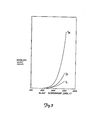
- Figure 3 illustrates normalized curves modeling the output signals from amplifiers 26, 28 and 33 relative to temperature.
- the output curves for the outputs of amplifiers 26 and 28 are labeled V 27 and V 32 , respectively, and the output from amplifier 33 is labeled V.
- the outputs are normalized at 1.200° F and the output curve V c is the modeled output set for a 4,200° F flame.
- microprocessor 20 is programmed to calculate the blade temperature from V c with a nonlinear program function.
- Equation (4) above indicates that the output V c is a function of blade temperature only and the effect of reflected radiation has been substantially reduced by use of the scaling factor K.
- the scaling factor K can be provided by a separate circuit connected between the output of amplifier 28 and the associated input of amplifier 33, if desired. It is further noted that the output from amplifier 33 (V c ) is independent of radiation due to sources at the calibration temperature where K was selected. For other flame and hot carbon particle temperatures, the output (V c ) is sensitive to the presence of such flame and hot carbon particles. The present invention substantially reduces such effects.
Landscapes
- Physics & Mathematics (AREA)
- General Physics & Mathematics (AREA)
- Spectroscopy & Molecular Physics (AREA)
- Radiation Pyrometers (AREA)
Applications Claiming Priority (2)
| Application Number | Priority Date | Filing Date | Title |
|---|---|---|---|
| US76390985A | 1985-08-08 | 1985-08-08 | |
| US763909 | 1985-08-08 |
Publications (2)
| Publication Number | Publication Date |
|---|---|
| EP0216458A1 true EP0216458A1 (fr) | 1987-04-01 |
| EP0216458B1 EP0216458B1 (fr) | 1990-10-24 |
Family
ID=25069142
Family Applications (1)
| Application Number | Title | Priority Date | Filing Date |
|---|---|---|---|
| EP19860305521 Expired EP0216458B1 (fr) | 1985-08-08 | 1986-07-17 | Pyromètre détecteur de la température |
Country Status (4)
| Country | Link |
|---|---|
| EP (1) | EP0216458B1 (fr) |
| JP (1) | JPH0684912B2 (fr) |
| CA (1) | CA1264090A (fr) |
| DE (1) | DE3675130D1 (fr) |
Cited By (2)
| Publication number | Priority date | Publication date | Assignee | Title |
|---|---|---|---|---|
| EP0708317A1 (fr) | 1994-10-21 | 1996-04-24 | Societe Europeenne De Propulsion | Pyromètre bichromatique rapide à fibre optique |
| GB2358059A (en) * | 2000-01-07 | 2001-07-11 | Rotadata Ltd | Pyrometric determination of radiance and/ or temperature |
Families Citing this family (2)
| Publication number | Priority date | Publication date | Assignee | Title |
|---|---|---|---|---|
| US4708474A (en) * | 1985-11-14 | 1987-11-24 | United Technologies Corporation | Reflection corrected radiosity optical pyrometer |
| JP2013148367A (ja) * | 2012-01-17 | 2013-08-01 | General Electric Co <Ge> | リアルタイムガスタービン制御および予測のためのスマート放射温度測定システム |
Citations (4)
| Publication number | Priority date | Publication date | Assignee | Title |
|---|---|---|---|---|
| US3759102A (en) * | 1971-03-25 | 1973-09-18 | Steel Corp | Apparatus for determining correct pyrometer readings with steam interference present |
| US4222663A (en) * | 1977-08-01 | 1980-09-16 | United Technologies Corporation | Optical pyrometer and technique for temperature measurement |
| GB2045425A (en) * | 1979-07-09 | 1980-10-29 | Negretti & Zambra Aviat Ltd | Detection of spurious high temperature sources in the field of view of a pyrometer |
| EP0119724A2 (fr) * | 1983-02-14 | 1984-09-26 | Uss Engineers And Consultants, Inc. | Pyromètre de radiations à deux détecteurs |
Family Cites Families (1)
| Publication number | Priority date | Publication date | Assignee | Title |
|---|---|---|---|---|
| US4708474A (en) | 1985-11-14 | 1987-11-24 | United Technologies Corporation | Reflection corrected radiosity optical pyrometer |
-
1986
- 1986-07-17 DE DE8686305521T patent/DE3675130D1/de not_active Expired - Fee Related
- 1986-07-17 EP EP19860305521 patent/EP0216458B1/fr not_active Expired
- 1986-07-28 CA CA000514784A patent/CA1264090A/fr not_active Expired
- 1986-08-08 JP JP18671786A patent/JPH0684912B2/ja not_active Expired - Lifetime
Patent Citations (4)
| Publication number | Priority date | Publication date | Assignee | Title |
|---|---|---|---|---|
| US3759102A (en) * | 1971-03-25 | 1973-09-18 | Steel Corp | Apparatus for determining correct pyrometer readings with steam interference present |
| US4222663A (en) * | 1977-08-01 | 1980-09-16 | United Technologies Corporation | Optical pyrometer and technique for temperature measurement |
| GB2045425A (en) * | 1979-07-09 | 1980-10-29 | Negretti & Zambra Aviat Ltd | Detection of spurious high temperature sources in the field of view of a pyrometer |
| EP0119724A2 (fr) * | 1983-02-14 | 1984-09-26 | Uss Engineers And Consultants, Inc. | Pyromètre de radiations à deux détecteurs |
Cited By (4)
| Publication number | Priority date | Publication date | Assignee | Title |
|---|---|---|---|---|
| EP0708317A1 (fr) | 1994-10-21 | 1996-04-24 | Societe Europeenne De Propulsion | Pyromètre bichromatique rapide à fibre optique |
| FR2726081A1 (fr) * | 1994-10-21 | 1996-04-26 | Europ Propulsion | Pyrometre bichromatique rapide a fibre optique |
| US5755510A (en) * | 1994-10-21 | 1998-05-26 | Societe Europeenne De Propulsionm | Fast bichromatic pyrometer for use with an optical fiber |
| GB2358059A (en) * | 2000-01-07 | 2001-07-11 | Rotadata Ltd | Pyrometric determination of radiance and/ or temperature |
Also Published As
| Publication number | Publication date |
|---|---|
| DE3675130D1 (de) | 1990-11-29 |
| EP0216458B1 (fr) | 1990-10-24 |
| CA1264090A (fr) | 1989-12-27 |
| JPH0684912B2 (ja) | 1994-10-26 |
| JPS6235232A (ja) | 1987-02-16 |
Similar Documents
| Publication | Publication Date | Title |
|---|---|---|
| US4764025A (en) | Turbine blade temperature detecting pyrometer | |
| US4708474A (en) | Reflection corrected radiosity optical pyrometer | |
| EP0385256B1 (fr) | Appareil de mesure de concentration de gaz de respiration utilisant deux longueurs d'ondes | |
| US5308161A (en) | Pyrometer apparatus for use in rapid thermal processing of semiconductor wafers | |
| US5332901A (en) | Gas analyzing apparatus and method for simultaneous measurement of carbon dioxide and water | |
| US7671984B2 (en) | Spectrometric measuring probe and method for recalibrating the same | |
| GB1602160A (en) | Pyrometers | |
| GB1580861A (en) | Apparatus for monitoring the colour of a product | |
| US5507576A (en) | Bichromatic pyrometer | |
| EP0084726B1 (fr) | Dispositif et procédé pour contrôler la concentration d'ammoniac gazeux dans des gaz d'échappement | |
| JPS6118965B2 (fr) | ||
| US5376783A (en) | Power meter with background subtraction | |
| EP0584519B1 (fr) | Méthode spectrophotométrique et spectrophotomètre pour réaliser la méthode | |
| US5326172A (en) | Multiwavelength pyrometer for gray and non-gray surfaces in the presence of interfering radiation | |
| JP2844503B2 (ja) | ガス測定装置 | |
| EP0216458B1 (fr) | Pyromètre détecteur de la température | |
| US5070244A (en) | Gas detection by infrared absorption | |
| US4057734A (en) | Spectroscopic apparatus with balanced dual detectors | |
| US6218666B1 (en) | Method of determining the concentration of a gas in a gas mixture and analyzer for implementing such a method | |
| US6504603B1 (en) | Method and device for detecting undesired matter in eggs | |
| US2844033A (en) | Radiant energy measurement methods and apparatus | |
| EP0261452A2 (fr) | Analyseur de gaz | |
| JP6530669B2 (ja) | ガス濃度測定装置 | |
| US4016423A (en) | Infrared analyzer of constant radiant energy | |
| JPS60253952A (ja) | ガス濃度測定方式 |
Legal Events
| Date | Code | Title | Description |
|---|---|---|---|
| PUAI | Public reference made under article 153(3) epc to a published international application that has entered the european phase |
Free format text: ORIGINAL CODE: 0009012 |
|
| AK | Designated contracting states |
Kind code of ref document: A1 Designated state(s): DE FR GB |
|
| 17P | Request for examination filed |
Effective date: 19870930 |
|
| 17Q | First examination report despatched |
Effective date: 19890328 |
|
| GRAA | (expected) grant |
Free format text: ORIGINAL CODE: 0009210 |
|
| AK | Designated contracting states |
Kind code of ref document: B1 Designated state(s): DE FR GB |
|
| REF | Corresponds to: |
Ref document number: 3675130 Country of ref document: DE Date of ref document: 19901129 |
|
| ET | Fr: translation filed | ||
| PLBE | No opposition filed within time limit |
Free format text: ORIGINAL CODE: 0009261 |
|
| STAA | Information on the status of an ep patent application or granted ep patent |
Free format text: STATUS: NO OPPOSITION FILED WITHIN TIME LIMIT |
|
| 26N | No opposition filed | ||
| PGFP | Annual fee paid to national office [announced via postgrant information from national office to epo] |
Ref country code: FR Payment date: 19990820 Year of fee payment: 14 Ref country code: DE Payment date: 19990820 Year of fee payment: 14 |
|
| PGFP | Annual fee paid to national office [announced via postgrant information from national office to epo] |
Ref country code: GB Payment date: 20010117 Year of fee payment: 15 |
|
| PG25 | Lapsed in a contracting state [announced via postgrant information from national office to epo] |
Ref country code: FR Free format text: LAPSE BECAUSE OF NON-PAYMENT OF DUE FEES Effective date: 20010330 |
|
| REG | Reference to a national code |
Ref country code: FR Ref legal event code: ST |
|
| PG25 | Lapsed in a contracting state [announced via postgrant information from national office to epo] |
Ref country code: DE Free format text: LAPSE BECAUSE OF NON-PAYMENT OF DUE FEES Effective date: 20010501 |
|
| PG25 | Lapsed in a contracting state [announced via postgrant information from national office to epo] |
Ref country code: GB Free format text: LAPSE BECAUSE OF NON-PAYMENT OF DUE FEES Effective date: 20010717 |
|
| GBPC | Gb: european patent ceased through non-payment of renewal fee |
Effective date: 20010717 |