EP0216471A2 - Dispositif d'étanchéité pour les passages des électrodes dans les fours électriques à arc - Google Patents
Dispositif d'étanchéité pour les passages des électrodes dans les fours électriques à arc Download PDFInfo
- Publication number
- EP0216471A2 EP0216471A2 EP86305921A EP86305921A EP0216471A2 EP 0216471 A2 EP0216471 A2 EP 0216471A2 EP 86305921 A EP86305921 A EP 86305921A EP 86305921 A EP86305921 A EP 86305921A EP 0216471 A2 EP0216471 A2 EP 0216471A2
- Authority
- EP
- European Patent Office
- Prior art keywords
- sealing device
- refractory
- electrode
- opening
- gas
- Prior art date
- Legal status (The legal status is an assumption and is not a legal conclusion. Google has not performed a legal analysis and makes no representation as to the accuracy of the status listed.)
- Ceased
Links
Images


Classifications
-
- H—ELECTRICITY
- H05—ELECTRIC TECHNIQUES NOT OTHERWISE PROVIDED FOR
- H05B—ELECTRIC HEATING; ELECTRIC LIGHT SOURCES NOT OTHERWISE PROVIDED FOR; CIRCUIT ARRANGEMENTS FOR ELECTRIC LIGHT SOURCES, IN GENERAL
- H05B7/00—Heating by electric discharge
- H05B7/02—Details
- H05B7/12—Arrangements for cooling, sealing or protecting electrodes
Definitions
- This invention relates to a sealing device for electrode openings in electric arc furnaces.
- furnace gases flow out mainly through the electrode openings in the roof. This is generally to be avoided and a basic attempt to meet this requirement has been to exhaust the furnace gases through an opening in the roof specifically present for exhaust purposes. This has not proved to be a significant success.
- the furnace gases being exhausted are generally undergoing combustion, that is present as flames, which sometimes reach a height of two or more metres. They always contain solid particles of iron oxides and calcium oxide (lime) which will be deposited on any available surface, including adjacent electrode surfaces.
- sealing devices which operate on the "air cushion" principle came into widespread use. These devices provide an annular chamber around the electrode into which such a quantity of air is blown that, during its outflow upwards along the electrode, there is maintained in the chamber a pressure slightly higher than that in the furnace interior, i.e. about 3 mm water column. This serves to keep the furnace gases within the furnace.
- Such sealing devices are made of metal and may be provided with water cooling or they may be made with an external metal casing and an internal fire-clay portion.
- the metal sealing devices without water cooling are simple to manufacture and initially provide a good seal, but their life is limited because of the deformation they undergo leading to increase of the opening which they define.
- the metal devices with water cooling are more complicated to manufacture and hence more expensive, but they have a life several times longer than that of comparable sealing devices without water cooling.
- Sealing devices of similar type but which are provided with an internal fire-clay portion have been proposed too. These devices have a substantial drawback due to the relatively low refractoriness of the fire-clay materials. Their chemical composition is generally such that they soften at about 1500°C. As a result of this, the size of the opening therein increases gradually during use; this impairs or even destroys the sealing action.
- All known sealing devices operating on the "air cushion" principle are provided with a duct-diffuser with a nozzle in the duct axis for achieving air delivery, and gas is delivered under pressure through this nozzle.
- This gas flow entrains in the duct-diffuser a volume of air from the atmosphere which is several times greater than itself.
- the gas-air flow enters the chamber around the electrode through a hole in the side wall of the device, and effectively stops totally the outflow of furnace gases.
- the gas supplied under pressure can be compressed air, steam, waste industrial nitrogen, or another convenient available gas.
- the choice of the gas under pressure is determined primarily by economic considerations. The nature of the gas does not influence the sealing action.
- a sealing device for emplacement over an electrode opening of an electric arc furnace and for providing an annular chamber around an electrode passing therethrough, which device comprises upper and lower portions defining cylindrical passages for the electrode and a central portion shaped internally to define a spiral-shaped passage around the electrode and having an entry opening for a gas-air flow into the spiral-shaped passage defined by said central portion, which opening houses a duct-diffuser with an axial nozzle therein for the supply of gas under pressure to the interior of the device, which portions comprise metal-encased refractory material, specifically a cylindrical metal casing around cylindrical refractory parts made of high-alumina material with an A12O3 content higher than 80% and defining said passages.
- the interior of the sealing device may be formed of refractory cement with an A12O3 content higher than 80% which is vibrationally cast in a mould formed by a cylinder-shaped metal part of the device and an internal fixed template.
- the internal template is withdrawn and the device, comprising a metal and a refractory portion, is subjected to drying. This is generally effected at about 150°C, but it is possible for the drying temperature to reach 220°C. During the drying the free moisture is totally removed, although the hydrate bond of the cement is not destroyed.
- the aforementioned mould is filled and compacted in any convenient way with a high-alumina ramming mass with an A12O3 content higher than 80%, preferably higher than 85%.
- the primary materials for preparing the mass can have a refractory content of 75-85% by weight of white corundum and 15-25% by weight kaolin, the mixture additionally containing, as bonding agent, phosphorous acid and/or phosphorus salts such as phosphates in a quantity of 5 to 15% with respect to the solid materials.
- bonding agent phosphorous acid and/or phosphorus salts such as phosphates
- phosphorous acid and/or phosphorus salts such as phosphates
- the internal template is withdrawn and the device is subjected to drying at about 150°C, although higher temperatures up to 220°C may be used. As a result, moisture and low-volatile components which may be present are removed, although the constitution water present in the chemical bonding between the solid refractory grains is not removed.
- the mechanical strength of the high-alumina cement or the high-alumina ramming mass often may be increased by incorporating therein so-called micro-reinforcements.
- short wires with a diameter of from 0.3 to 2.0 mm and a length of from 10 to 40 mm are added thereto in a quantity of 0.5 to 6% with respect to the weight of the high-alumina material.
- These wires may be formed of carbon steel or of stainless chrome-nickel steel. It is also possible to use wires of other metals or alloys.
- the sealing device is provided with one or more openings from the side into the interior thereof for the entry of a flow of air or gas-air mixture, and this flow maintains the necessary pressure in the annular chamber formed between sealing device and electrode while not allowing any outflow of furnace gases.
- Tangential delivery of the gas-air flow is preferably to be used. It is also possible to direct the flow radially by using a deflector-distributor which distributes the flow of gas-air mixture into the two halves of the chamber.
- the deflector-distributor is made of metal or of a refractory material. From a practical point of view, tangential delivery is preferred in the majority of cases.
- the external metal casing and the refractory internal parts in the chamber are of cylindrical shape with their axes being coincident, the thickness and the mechanical strength of the refractory parts in the zone of the supply opening for the gas flow may be reduced.
- the shape of the chamber as seen from above is preferably not circular but that of an Archimedean spiral and the chamber is referred to herein as "a spiral-shaped chamber".
- the region of the entry opening for the gas-air flow is preferably given enhances mechanical strength by being provided in of an external boss formed from the metal and the refractory parts of the sealing device. This has the effect of increasing the thickness and strength of the refractory part in the region of the entry opening.
- a further increase in thickness of the refractory part is achieved in this region by displacing the axis of the spirally shaped chamber with respect to the axis of the metal cylinder-shaped casing in a direction opposite and almost perpendicular to the entry opening for the gas-air flow.
- a sealing device embodying this invention consists of three members: upper and base members each defining a circular opening for the through passage of the electrode, and a central member with the spiral-shaped chamber and an entry opening for the gas-air flow. These three members can be manufactured separately and can subsequently be connected in an appropriate manner. It is also possible to manufacture the three members as a single body. In this case the sealing device has a common metal casing and an integral refractory body.
- the sealing device does not have its own base member.
- the device seats directly upon the refractory masonry of the roof of the furnace, this masonry serving as the base member of the device.
- the base member be manufactured separately and that it consist of the aforedescribed metal and refractory portions.
- the necessary gas-air mixture for the sealing device is produced in any convenient way in the injector, which consists of a cylindrical duct-diffuser and an externally mounted nozzle for the delivery of gas under pressure.
- the nozzle is axially disposed in the duct.
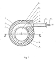
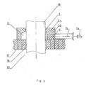
- the sealing device illustrated in Figures 1 and 2 consists of three hollow cylindrical members: upper and base members respectively of cylindrical shape and defining a cylindrical electrode opening 3 and 14 respectively and an intermediate member defining an electrode chamber 11 whose axis is displaced with respect to the axis of the cylinder defined by the external surface of the intermediate member in a direction away from and almost at right angles to an inlet duct 15 for gas-air flow.
- the intermediate member of the sealing device includes a refractory spiral-shaped part 7 defining what is a spiral-shaped chamber 11 and has a projection 5 of its metal casing 12 and a projection 8 of the refractory material of part 7 providing a side passageway 9 for an entry opening 6 for gas-air flow.
- the axis of the refractory spiral-shaped part 7 is displaced with respect to that of the cylindrically-shaped metal casing 12 whereas the longitudinal axes of the refractory parts 2 and 13 of the upper member and the base member respectively coincides with the common axis of their casings 1 and 12 respectively.
- the upper member of the sealing device consists of a cylindrical metal casing 1 and an internal refractory part 2 with cylindrical passage 3 for an electrode.
- the intermediate member of the sealing device consists of the cylindrical metal casing 4 with metal projection 5 in the region of the opening 6 for connection with the duct-diffuser 15; the spirally-shaped part 7 which is of high alumina content with an external boss 8 which incorporates the side passageway 9, provided for the passage of the gas-air mixture.
- the internal wall of the refractory part 7 forms the spiral-shaped chamber 11 which lies around the graphite electrode 10.
- the base member of the sealing device consists, like the upper member, of a cylindrical metal casing 12 and a refractory part 13 with a cylindrical opening 14.
- the refractory parts 2, 7, 8 and 13 all consist, according to this invention, of refractory materials with an Al2O3 content higher than 80%. They are made by casting and vibrating high-alumina cement or by compacting high-alumina ramming mass in moulds formed by the metal casing elements 1, 4 and 5 and 12 and by internal templates fitted therein. After the setting of the refractory cement or of the refractory ramming mass, the templates are withdrawn and the three parts of the sealing device, consisting of metal parts 1, 4 and 5 and 12 and refractory parts 2, 7 and 8 and 13 respectively are dried at a temperature of about 150°C. During the drying, moisture and possibly present compounds of low volatility are evaporated but the constitution water of the chemical bond of the ramming mass is not lost.
- the sealing device is provided with a duct-diffuser 15 having a nozzle 16 shown in exploded view in Figures 1 and 2, intended for the delivery of gas under pressure.
- the duct diffuser and nozzle are manufactured of metal.
- the sealing device After the manufacture of the three members of the sealing device, they are connected in an appropriate way such that the axes of the metal casings thereof coincide.
- the sealing device is seated upon refractory bricks 17, which surround an electrode opening 18 in the furnace roof.
- this sealing device is the same as that of known sealing devices of like type:
- the outflow of the gas almost exclusively through the annular aperture 3 between refractory portion 2, formed by the refractory part 2 and the graphite electrode 10, there is maintained in the chamber 11 a pressure which is slightly higher than the pressure in the upper part of furnace space 19.
- the sealing device according to Figure 3 is essentially an integral body shaped to correspond to the upper and central member of the sealing device of Figures 1 and 2 with like reference numerals denoting like parts in the respective figures.
- the sealing device seats directly upon the refractory bricks 17 which enclose the electrode opening 18 in the furnace roof.
- a particular advantage of a sealing device according to the invention is that its internal portion consists of high-alumina refractory which has a resistance to flame at temperatures higher than 1800°C, i.e. 250-300°C higher than the temperature withstood by fire-clay refractories.
- This elevation of fire-resistance by 250-300°C is of decisive importance for the successful use of the sealing device with steelmaking electric arc furnaces. It enables the sealing device to remain operable for considerably longer and hence enables reliable electrical insulation to be maintained between sealing devices of electrodes of adjacent phases. Even if deposits of electroconductive powder on the furnace roof give rise to a momentary powerful arc between two adjacent sealing devices, this does not have damaging consequences. All that may happen is that melting of the casing occurs over a very small area and does not generally influence the sealing action.
- the high resistance of the sealing device to the effect of flame does not permit any solid particles carried by the furnace gases to become adhered to it. If, nevertheless, in certain cases internal deposits mainly of slag drops are formed, their adhesion to the refractory material of the device is only mechanical and they can be easily removed.
- the good resistance of the sealing device to damaging influences enables prolonged maintenance of a good seal.
- the furnace roof remains effective for longer, there is a substantial improvement in the conditions under which operation of the electrode holder heads can take place, there is the possibility of control of the pressure within the furnace space with all related favourable consequences and there is a considerable reduction of the dust-loading in steelmaking plant in which sealing device is used.
- a particularly important result of the good sealing is the reduction in electrode consumption. This is shown particularly well when using coated electrodes. There is reduced wear of the electrode coating and the relative extent of secondary consumption of electrode material due to a high rate of oxidation in the chamber of the sealing device is generally eliminated.
- a final important advantage of the sealing device of this invention is that the manufacture of an integral large-size refractory body of high-alumina cement or of high-alumina ramming mass does not require baking at a temperature of 1350-1400°C as in the case of the fire-clay refractory materials. Only drying at a temperature of the order of 150°C is necessary.
Landscapes
- Physics & Mathematics (AREA)
- Engineering & Computer Science (AREA)
- Plasma & Fusion (AREA)
- Vertical, Hearth, Or Arc Furnaces (AREA)
- Furnace Details (AREA)
- Discharge Heating (AREA)
Applications Claiming Priority (2)
| Application Number | Priority Date | Filing Date | Title |
|---|---|---|---|
| BG71330/85 | 1985-08-02 | ||
| BG8571330A BG44020A1 (en) | 1985-08-02 | 1985-08-02 | Sealer of electrode openings in electro- arc furnaces and methods for its manufacture |
Publications (2)
| Publication Number | Publication Date |
|---|---|
| EP0216471A2 true EP0216471A2 (fr) | 1987-04-01 |
| EP0216471A3 EP0216471A3 (fr) | 1989-03-08 |
Family
ID=3916015
Family Applications (1)
| Application Number | Title | Priority Date | Filing Date |
|---|---|---|---|
| EP86305921A Ceased EP0216471A3 (fr) | 1985-08-02 | 1986-08-01 | Dispositif d'étanchéité pour les passages des électrodes dans les fours électriques à arc |
Country Status (6)
| Country | Link |
|---|---|
| US (1) | US4703493A (fr) |
| EP (1) | EP0216471A3 (fr) |
| JP (1) | JPS62110297A (fr) |
| KR (1) | KR870002744A (fr) |
| BG (1) | BG44020A1 (fr) |
| BR (1) | BR8603681A (fr) |
Cited By (1)
| Publication number | Priority date | Publication date | Assignee | Title |
|---|---|---|---|---|
| FR2692665A1 (fr) * | 1992-06-17 | 1993-12-24 | Unimetall Sa | Dispositif d'étanchéité partielle des électrodes de fours électriques à arc. |
Families Citing this family (3)
| Publication number | Priority date | Publication date | Assignee | Title |
|---|---|---|---|---|
| BE1000899A4 (nl) * | 1987-09-02 | 1989-05-09 | Picanol Nv | Werkwijze voor het kontroleren van kettingbreuken bij weefmachines, en inrichting die deze werkwijze toepast. |
| FI123373B (fi) * | 2008-06-06 | 2013-03-15 | Outotec Oyj | Tiivistyslaite |
| CN109068433B (zh) * | 2018-09-11 | 2023-10-20 | 宜兴瑞泰耐火材料有限公司 | 一种电石炉电极密封装置 |
Family Cites Families (2)
| Publication number | Priority date | Publication date | Assignee | Title |
|---|---|---|---|---|
| DE2045133C3 (de) * | 1969-09-19 | 1980-01-17 | Dmz Lenin | Abdichtungsvorrichtung für Elektroden in Lichtbogenöfen |
| DE3271455D1 (en) * | 1981-11-20 | 1986-07-03 | Coated Electrodes Ltd | Apparatus for sealing electrodes in electric arc furnaces |
-
0
- BR BR8603681A patent/BR8603681A/pt unknown
-
1985
- 1985-08-02 BG BG8571330A patent/BG44020A1/xx unknown
-
1986
- 1986-07-31 JP JP61181201A patent/JPS62110297A/ja active Pending
- 1986-08-01 EP EP86305921A patent/EP0216471A3/fr not_active Ceased
- 1986-08-02 KR KR1019860006389A patent/KR870002744A/ko not_active Ceased
- 1986-08-04 US US06/892,943 patent/US4703493A/en not_active Expired - Fee Related
Cited By (1)
| Publication number | Priority date | Publication date | Assignee | Title |
|---|---|---|---|---|
| FR2692665A1 (fr) * | 1992-06-17 | 1993-12-24 | Unimetall Sa | Dispositif d'étanchéité partielle des électrodes de fours électriques à arc. |
Also Published As
| Publication number | Publication date |
|---|---|
| US4703493A (en) | 1987-10-27 |
| JPS62110297A (ja) | 1987-05-21 |
| KR870002744A (ko) | 1987-04-06 |
| BR8603681A (pt) | 1987-03-10 |
| EP0216471A3 (fr) | 1989-03-08 |
| BG44020A1 (en) | 1988-09-15 |
Similar Documents
| Publication | Publication Date | Title |
|---|---|---|
| US4647020A (en) | Gas-permeable element of a refractory material | |
| US4378106A (en) | Refractory gas permeable structural unit | |
| US4735400A (en) | Plug for a refining apparatus | |
| CA1177643A (fr) | Element de construction refractaire permeable aux gaz | |
| EP0216471A2 (fr) | Dispositif d'étanchéité pour les passages des électrodes dans les fours électriques à arc | |
| CA2059796C (fr) | Bruleur leger | |
| US5067693A (en) | Electric arc oven for treating molten metals with a gas and a process therefor | |
| US4717334A (en) | Ceramic burner having high turndown ratio | |
| US6872344B2 (en) | Gas blowing plug and manufacturing method therefor | |
| US5156801A (en) | Low porosity-high density radial burst refractory plug with constant flow | |
| US4668180A (en) | Ceramic burner having high turndown ratio | |
| JP3309512B2 (ja) | 銅精製炉 | |
| WO1997002365A1 (fr) | Appareil permettant la post-combustion de composants combustibles de l'atmosphere d'un four metallurgique | |
| US5299785A (en) | Gas purging plug for electric-arc furnaces and the corresponding electric-arc furnace | |
| US4698825A (en) | Protective coating of temperature resistant materials for the metal shaft of combination electrodes for the electric steel production | |
| US3343827A (en) | Taphole for a metallurgical vessel | |
| WO2003106907A1 (fr) | Four de fusion | |
| Lepoutre et al. | Arc Furnace and Process for Smelting Scrap | |
| US5200135A (en) | Method to improve the service life of gas injection devices used to introduce a gas into molten metal | |
| JPH0410558Y2 (fr) | ||
| JPH01272707A (ja) | 高炉炉壁冷却用ステーブ | |
| WO1997002364A1 (fr) | Procede et appareil permettant la combustion de composants combustibles de l'atmosphere de fours metallurgiques | |
| SU1245599A1 (ru) | Конвертер (его варианты) | |
| JPS6360091B2 (fr) | ||
| JPS5929950Y2 (ja) | 転炉羽口部の炉壁の構造 |
Legal Events
| Date | Code | Title | Description |
|---|---|---|---|
| PUAI | Public reference made under article 153(3) epc to a published international application that has entered the european phase |
Free format text: ORIGINAL CODE: 0009012 |
|
| AK | Designated contracting states |
Kind code of ref document: A2 Designated state(s): AT BE CH DE FR GB IT LI NL SE |
|
| PUAL | Search report despatched |
Free format text: ORIGINAL CODE: 0009013 |
|
| AK | Designated contracting states |
Kind code of ref document: A3 Designated state(s): AT BE CH DE FR GB IT LI NL SE |
|
| 17P | Request for examination filed |
Effective date: 19890329 |
|
| 17Q | First examination report despatched |
Effective date: 19890712 |
|
| STAA | Information on the status of an ep patent application or granted ep patent |
Free format text: STATUS: THE APPLICATION HAS BEEN REFUSED |
|
| 18R | Application refused |
Effective date: 19900421 |
|
| RIN1 | Information on inventor provided before grant (corrected) |
Inventor name: SAVOV, PETER HRISTOV Inventor name: VELEV, VELYO TODOROV Inventor name: PENEV, PENYO IVANOV Inventor name: IVANOV, IVAN KOLEV Inventor name: VULCHEV, ALEXANDER YORDANOV Inventor name: BAKALOV, NIKOLAY GEORGIEV |