EP0216500B1 - Elektromagnetischer Induktionsapparat - Google Patents
Elektromagnetischer Induktionsapparat Download PDFInfo
- Publication number
- EP0216500B1 EP0216500B1 EP86306422A EP86306422A EP0216500B1 EP 0216500 B1 EP0216500 B1 EP 0216500B1 EP 86306422 A EP86306422 A EP 86306422A EP 86306422 A EP86306422 A EP 86306422A EP 0216500 B1 EP0216500 B1 EP 0216500B1
- Authority
- EP
- European Patent Office
- Prior art keywords
- winding
- transformer
- windings
- electromagnetic induction
- induction apparatus
- Prior art date
- Legal status (The legal status is an assumption and is not a legal conclusion. Google has not performed a legal analysis and makes no representation as to the accuracy of the status listed.)
- Expired - Lifetime
Links
Images





Classifications
-
- H—ELECTRICITY
- H01—ELECTRIC ELEMENTS
- H01F—MAGNETS; INDUCTANCES; TRANSFORMERS; SELECTION OF MATERIALS FOR THEIR MAGNETIC PROPERTIES
- H01F30/00—Fixed transformers not covered by group H01F19/00
- H01F30/06—Fixed transformers not covered by group H01F19/00 characterised by the structure
- H01F30/10—Single-phase transformers
-
- H—ELECTRICITY
- H01—ELECTRIC ELEMENTS
- H01F—MAGNETS; INDUCTANCES; TRANSFORMERS; SELECTION OF MATERIALS FOR THEIR MAGNETIC PROPERTIES
- H01F27/00—Details of transformers or inductances, in general
- H01F27/34—Special means for preventing or reducing unwanted electric or magnetic effects, e.g. no-load losses, reactive currents, harmonics, oscillations, leakage fields
- H01F27/38—Auxiliary core members; Auxiliary coils or windings
-
- H—ELECTRICITY
- H01—ELECTRIC ELEMENTS
- H01F—MAGNETS; INDUCTANCES; TRANSFORMERS; SELECTION OF MATERIALS FOR THEIR MAGNETIC PROPERTIES
- H01F29/00—Variable transformers or inductances not covered by group H01F21/00
- H01F29/02—Variable transformers or inductances not covered by group H01F21/00 with tappings on coil or winding; with provision for rearrangement or interconnection of windings
Definitions
- This invention relates to an electromagnetic induction apparatus which comprises a transformer and which is utilized for power transmission and distribution systems, etc., and more particularly to an electromagnetic induction apparatus which does not require the installation of a shunt reactor.
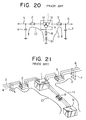
- Fig. 20 is a circuit diagram showing the single-line connection state of a substation which employs and electromagnetic induction apparatus comprising a transformer as has heretofore been utilized in a power transmission or distribution system
- Fig. 21 is a perspective view showing a practical construction in the case where the circuit in Fig. 20 is three phases.
- 1 designates a transformer having a primary winding 1a and a secondary winding 1b, and a tertiary winding 1c which is electromagnetically coupled to the primary winding 1a as well as the secondary winding 1b.
- a primary side switching device 2 is connected to the primary winding 1a, a primary side transmission or distribution line 3 has one end connected to the primary side switching device 2 and the other end connected to an external circuit (not shown), and a capacitance 4 is formed between the primary side transmission or distribution line 3 and ground.
- a secondary side switching device 5 is connected to the secondary winding 1b, a secondary side transmission or distribution line 6 has one end connected to the secondary side switching device 5 and the other end connected to an external circuit (not shown), and a capacitance 7 is formed between the secondary side transmission or distribution line 6 and ground.
- a tertiary side switching device 8 is connected to the tertiary winding 1c, and a shunt reactor 9 has one end connected to the tertiary side switching device 8 and the other end grounded or which is star- or delta-connected in three phases. The flows 10 and 11 of "leading" reactive powers are supplied from the shunt reactor 9 to the respective capacitances 4 and 7 when the switching devices 2, 5 and 8 are closed.
- the switching devices 2, 5, and 8 are closed, so that the "leading" reactive powers are supplied from the shunt reactor 9 through the transformer 1 to the capacitance 4 of the primary side transmission or distribution line 3 and the capacitance 7 of the secondary side transmission or distribution line 6 respectively as indicated by the arrows 10 and 11.
- the switching devices 2, 5 and 8 are opened, and the transformer 1 and the shunt reactor 9 are separated from the power system.
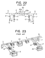
- Fig. 22 is a circuit diagram showing the single-line connection state of another prior-art example
- Fig. 23 is a perspective view showing a practical construction in the case where the circuit in Fig. 22 is used in three phases.
- Symbols 2 - 7 denote the same constituents as those shown in Figs. 20 and 21.
- a transformer 20 has a primary winding 20a and a secondary winding 20b, a switching device 12 on the primary side is connected to the primary side transmission or distribution line 3, and a shunt reactor 13 on the primary side has one end connected to the switching device 12 and the other end grounded or which is star- or delta-connected in three phases.
- a switching device 14 on the secondary side is connected to the secondary side transmission or distribution line 6, and a shunt reactor 15 on the secondary side has one end connected to the switching device 14 and the other end grounded or which is star-or delta-connected in three phases.
- the flows 16 and 17 of "leading" reactive powers are respectively supplied from the shunt reactors 13, 15 through the switching devices 12, 14 to the capacitances 4, 7 when the switching devices 12, 14 are closed.
- the switching devices 2, 5, 12 and 14 are closed, so that the "leading" reactive powers are supplied from the shunt reactors 13 and 15 through the corresponding transmission or distribution lines 3 and 6 to the respective capacitances 4 and 7 as indicated by the arrows 16 and 17.
- the switching devices 2, 5, 12 and 14 are opened, and the transformer 20 and the shunt reactors 13, 15 are separated from the power system.
- the transmission or distribution lines 3 and 6 are overhead lines of long distances or where they are constructed of cables even when they are of short distances, they have great capacitances 4 and 7, which consume "leading" reactive powers.
- the supply of the reactive powers from a power station (not shown) in a remote place results in inflicting heavy power losses on the power transmission or distribution system and spoiling the stability of this system.
- the "leading" reactive powers which the transmission or distribution lines 3 and 6 require are supplied from the substation near these lines 3 and 6 by disposing the phase modifying means, namely, the shunt reactor 9 or shunt reactors 13, 15 as shown in Figs. 20 - 23.
- Fig. 24 is an equivalent circuit diagram of the transformer 20 having the two windings as shown in Fig. 22, and Fig. 26 is a horizontal partial sectional view of the transformer 20.
- 21 indicates the primary side terminal of the transformer 20, 22 the secondary side terminal of the transformer 20, 23 a magnetic space defined between the primary winding 20a and the secondary winding 20b, 24 a leakage flux generated in the space 23 by the primary winding 20a and the secondary winding 20b, X the leakage reactance of the transformer 20 induced by the leakage flux 24, r the winding resistance of the transformer 20, and Zm the excitation impedance of the transformer 20.
- 25 indicates the primary side terminal of the transformer 1, 26 the secondary side terminal thereof, and 27 the tertiary side terminal thereof.
- the prior-art electromagnetic induction apparatus in the substation is equipped with the shunt reactor 9 or shunt reactors 13, 15 as the phase modifying means for compensating the "leading" reactive powers which are consumed by the capacitances 4, 7 between the respective transmission or distribution lines 3, 6 and ground. Therefore, it has had several problems to be explained below:
- French Patent Specification 45888 discloses an arrangement in which the primary and secondary windings of a pair of transformers are serially connected to one another. A compensator winding is wound around the core of each of the transformers. When both transformers are used, the compensator coils are connected to one another.
- GB Patent Specification 5190 discloses a transformer arrangement in which the secondary winding is divided so that the winding in effect is provided with supplementary coils connected in series with the secondary winding. The purpose of this is to prevent or lessen the risk of damage in the event of excessive loads being supplied to the transformer.
- United States Patent Specification 2 221 619 discloses an electrical induction apparatus in which a primary winding is divided into two, respective parts being wound on separate cores. A secondary winding is wound on one of the cores. The secondary winding of the other core is connected by means of tap connections to the secondary winding of the first core.
- This invention has been made in orderr to solve all the problems as mentioned above, and has for its object the provision of an electromagnet induction apparatus which is so constructed as to have the function of supplying "leading" reactive powers without the installation of a shunt reactor, thereby to reduce the space and to lower the power loss.
- Another objection of this invention is to make the capacity of an equivalent shunt reactor which functions to supply "leading" reactive power variable.
- an electromagnetic induction apparatus for use in power transmission and distribution systems, the apparatus comprising a transformer having at least two windings connected to external circuits characterised in that a short-circuit winding is provided, and said at least two windings and the short-circuit winding are wound on a single core as well as being electromagnetically coupled to each other.
- an electromagnetic induction apparatus for use in power transmission and distribution systems, the apparatus comprising a transformer having at least two windings connected to external circuits, characterised in that a reactor winding is provided and said at least two windings and the reactor winding are wound on a single core as well as being electromagnetically coupled to each other, one of said at least two windings being provided with a tap to form this winding into a tap winding, said reactor winding having one end thereof connected to one end of said tap winding and having the other end thereof connected to said tap.
- two windings operate as an ordinary transformer, while a leakage flux appears in the magnetic space between the two windings and a short-circuit winding, and it equivalently functions as a shunt reactor, to supply "leading" reactive powers to transmission or distribution lines and capacitances.
- a tap voltage which is lower than the open-circuit voltage of a reactor winding is forcibly applied from a tap to the reactor winding, to generate a desired magnitude of leakage flux between the reactor winding and a tap winding.
- Fig. 1 is a circuit diagram in a single-line connection state showing the embodiment of this invention as a transformer which has, for example, three windings.
- FIGs. 1-12, 1a-1c, 2-7, 10 and 11 indicate the same portions as in the prior art examples stated before, and 1A indicates a transformer corresponding to the transformer 1.
- the core of the transformer 1A is denoted by 1d and S is a short-circuit line which short-circuits both the ends of the tertiary winding 1c and due to which the tertiary winding 1c becomes a short-circuit winding.
- a leakage flux 18 is induced between the tertiary winding 1c and the primary winding 1a or secondary winding 1b by the short-circuit current of the tertiary winding 1c, and though not shown, such a leakage flux is also generated between the primary winding 1a and the secondary winding 1b.
- the leakage flux 18 passes through a magnetic space 19 which is illustrated only between the secondary winding 1b and the tertiary winding 1c here.
- a switching device 29 is added to the short-circuit line S.
- the switching device may well be connected between one end of the tertiary winding 1c and ground by leading the terminal of the tertiary winding 1c out of the transformer 1A as shown in Fig. 9, or between the lines of the tertiary winding connected in three phases.
- a power source V0 such as a power station (not shown) or the like is connected to the primary winding 1a, and a magnetic flux 18A is generated in the core 1d by the power source V0 when the switching device 29 has been opened.
- the tertiary winding 1c falls into an unshorted state, and the shunt reactor function vanishes.
- the switching device 29 is closed as depicted in Fig. 12, the tertiary winding 1c serves as the short-circuit winding and gives rise to the shunt reactor function, quite similarly to the state in which the short-circuit line S is provided as illustrated in Figs. 1 and 2. That is, the supply of the "leading" reactive powers 10, 11 can be on-off-controlled as is necessary by means of the switching device 29.
- the power source V0 of the power station (not shown) is connected to the primary winding 1a to excite the transformer 1A.
- the magnetic flux 18A is generated in the core 1d and interlinks with the primary winding 1a, secondary winding 1b and tertiary winding 1c in common.
- voltages proportional to the numbers of turns of the respective windings are generated across the primary winding 1a, secondary winding 1b and tertiary winding 1c. That is, in the state of Fig.
- the output terminals of the secondary winding 1b are connected to the external circuit (not shown), thereby to operate as the output terminals of the ordinary transformer.
- the tertiary winding 1c since the tertiary winding 1c is in the open state, it is merely generating the voltage. Accordingly, no current flows through the tertiary winding 1c, and the tertiary winding 1c is not supplying electric power externally.
- magnetic energy Q is generated in the magnetic space 19, and the value thereof is expressed by Q ⁇ fB2V where f denotes the frequency of the power source V0, B the flux density of the magnetic space 19 and V the volume of the magnetic space 19.
- a short-circuit current ⁇ 3 of a magnitude establishing a magnetic field of the flux density B in the magnetic space 19 flows through the tertiary winding 1c.
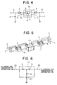
- the leakage flux 18 functions equally to the shunt reactor(s) 9 or 13, 15 in the prior-art examples shown in Figs. 20 to 23 and supplies the "leading" reactive powers 10, 11 to the capacitances 4, 7 of the primary side and secondary side transmission or distribution lines 3, 6 as shown in Figs. 4, 5, 9 and 10.
- the leakage flux 24 appears also in the two-winding transformer 20 or three-winding transformer 1 of the prior-art construction. As illustrated in the equivalent circuit of Fig. 25 or 27, however, the leakage reactance functions as the series reactance which is connected in series with the circuit.
- the equivalent circuit of the transformer 1A with the tertiary winding 1c short-circuited is expressed as in Fig. 6.
- 25-27 and X1-X3 are the same as in Fig. 27.
- the reactance X3 on the tertiary side functions as a parallel reactance which is connected in parallel with the circuit. That is, connecting the primary side transmission or distribution line 3 and the secondary side transmission or distribution line 6 to the primary side terminal 25 and the secondary side terminal 26 respectively corresponds to connecting "a shunt reactor whose reactance has the magnitude X3" in parallel with the power transmission or distribution system.
- the two-winding transformer when it is further provided with the tertiary winding 1c which is electromagnetically coupled to the primary winding 1a and the secondary winding 1b, it becomes identical to the construction of the three-winding transformer 1A and can also be operated similarly to the shunt reactor.
- the three-winding transformer 1A with both the ends of the tertiary winding 1c short-circuited functions also as the shunt reactor whose reactance has the magnitude X3, without spoiling the original voltage transformation function of the transformer and can supply the "leading" reactive powers to the capacitances 4, 7 of the transmission or distribution lines 3, 6.
- the voltage of the tertiary winding 1c can be selected at will irrespective of the voltages of the primary transmission or distribution line 3 and the secondary transmission or distribution line 6. Therefore, when the voltage across the tertiary winding 1c is rendered sufficiently low, the transformer 1A need not be especially enlarged.
- the transformer 1A is constructed as a shell type
- the transformer may also be constructed with a core type one as shown in Fig. 7.
- a gapped-core structure may well be adopted by interposing a gapped core 28 as shown in Fig. 8.
- transformer 1A of the three windings has been explained as an example, it is needless to say that, even when the invention is applied to a transformer of four or more windings not shown, an electromagnetic induction apparatus having the same functional effect as stated above can be realized by short-circuiting the tertiary winding.
- FIG. 13 is a circuit diagram showing the embodiment of another aspect of performance of this invention
- Fig. 14 is a perspective view showing a practical construction corresponding to Fig. 13
- Figs. 15 and 16 are horizontal partial sectional views respectively showing the states in which a tertiary winding in Fig. 14 is opened and is connected to a tap.
- 1a-1d, 18 and 19 denote portions similar to those described before
- 1B denotes a transformer corresponding to the transformer 1A.
- the secondary winding 1b is provided with a plurality of taps 30, and owing to which the secondary winding 1b becomes a tap winding.
- the tertiary winding 1c has one end connected to one end of the secondary winding 1b at a node P and has the other end connected to one of the plurality of taps 30, thereby to become a reactor winding.
- the primary side transmission or distribution line namely, the power source V0 of a power station or the like be connected to the primary winding 1a in the state in which the tertiary winding 1c as the reactor winding is open as depicted in Fig. 15.
- the magnetic flux 18A of a magnitude ⁇ 0 is generated in the core 1d and interlinks with the primary winding 1a, secondary winding 1b and tertiary winding 1c in common.
- This state is the same as in the case of Fig. 11.
- V10-V30 K ⁇ 0N3 (5)
- K K: constant.
- the secondary winding 1b can be used for the ordinary transformer when connected to the secondary side transmission or distribution line, namely, the external circuit.
- the tertiary winding 1c since the tertiary winding 1c is in the open state, it is merely generating the voltage V30 and does not execute the reactor function at all.
- one end of the tertiary winding 1c is connected to one end of the secondary winding 1b through the node P, and the other end of the tertiary winding 1c is connected to one of the taps 30, whereby a tap voltage V3 lower than the open-circuit voltage V30 as evaluated with Eqs. (3) and (5) is forcibly applied to the tertiary winding 1c.
- the leakage flux 18C of the magnitude ⁇ flows through the magnetic space 19, whereby predetermined magnetic energy is generated to effect the shunt reactor function.
- the value ⁇ of the magnetic flux 18B interlinking with the tertiary winding 1c varies in proportion to the tap voltage V3.
- the value ⁇ of the leakage flux 18C flowing through the magnetic space 19 changes simultaneously, so that the magnitude of the magnetic energy of the magnetic space 19 changes to change the capacity of the shunt reactor.
- the state in which the tap voltage V3 is rendered zero is the same as the case illustrated in Fig. 12.
- the value ⁇ 0 of the magnetic flux 18A in the open-circuit condition flows entirely to the magnetic space 19 upon being connected to the tap and the capacity of the shunt reactor becomes the maximum.
- an electromagnetic induction apparatus comprising a shunt reactor of variable capacity can be realized even with a transformer of four or more windings by using one of the windings as a reactor winding and another as a tap winding.
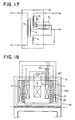
- a changer 31 for changing the taps 30 in an on-load condition may well be disposed between the other end of the tertiary winding 1c and the taps 30 as shown in a circuit diagram of Fig. 17.
- the change of the taps 30, in other words, the alteration of the capacity of the shunt reactor can be performed in the energized state.
- the magnetic space 19 through which the leakage flux 18C passes has been illustrated as the air-core structure as depicted in Fig. 16, it may well be a gapped-core structure with a gap core 28 interposed therein as depicted in Fig. 18.
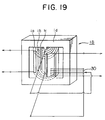
- transformer 1B as the electromagnetic induction apparatus has been illustrated as the shell type transformer, it may well be a core type one as shown in Fig. 19.
- a short-circuit winding which is electromagnetically coupled to at least two windings is disposed.
- a reactor winding which is electromagnetically coupled to at least two windings, one being a tap winding, and which is connected between one end of the tap winding and a tap is disposed, and the difference flux of respective magnetic fluxes appearing when the reactor winding is opened and is connected to the tap is generated in a magnetic space.
Landscapes
- Engineering & Computer Science (AREA)
- Power Engineering (AREA)
- Coils Of Transformers For General Uses (AREA)
Claims (9)
- Elektromagnetischer Induktionsapparat zur Verwendung in Stromübertragungs- und Stromverteilungsanlagen, aus einem Transformator (1A), der mindestens zwei Wicklungen (1a, 1b) aufweist, die mit externen Stromkreisen verbunden sind, dadurch gekennzeichnet, daß eine Kurzschlußwicklung (1c) vorgesehen ist, und die besagten mindestens zwei Wicklungen und die Kurzschlußwicklung auf demselben Kern angeordnet sind und elektromagnetisch miteinander gekoppelt sind.
- Elektromagnetischer Induktionsapparat gemäß Anspruch 1, dadurch gekennzeichnet, daß ein magnetischer Zwischenraum (19) zwischen der Kurzschlußwicklung (1c) und jeder der mindestens zwei Wicklungen (1a, 1b) eine Luftkern-Struktur bildet.
- Elektromagnetischer Induktionsapparat gemäß Anspruch 1, dadurch gekennzeichnet, daß ein magnetischer Zwischenraum (19) zwischen der Kurzschlußwicklung (1c) und jeder der mindestens zwei Wicklungen (1a, 1b) eine Luftspaltkern-Struktur (28) bildet.
- Elektromagnetischer Induktionsapparat gemäß Anspruch 1, dadurch gekennzeichnet, daß die Schalt-vorrichtung (29) mit einem Ende der besagten Kurzschlußwicklung (1c) verbunden ist.
- Elektromagnetischer Induktionsapparat zur Verwendung in Stromübertragungs- und Stromverteilungsanlagen, aus einem Transformator (1A) mit mindestens zwei Wicklungen (1a, 1b), die mit externen Stromkreisen verbunden sind, dadurch gekennzeichnet, daß eine Drosselwicklung (1c) vorgesehen ist, und die besagten mindestens zwei Wicklungen und die Drosselwicklung auf demselben Kern angeordnet sind und elektromagnetisch miteinander gekoppelt sind, wobei eine der mindestens zwei Wicklungen (1a, 1b) mit einer Anzapfung (30) versehen ist, um aus dieser Wicklung eine Anzapfungswicklung (1b) zu machen, und wobei ein Ende der Drosselwicklung (1c) mit einem Ende der Anzapfungswicklung (1b) verbunden ist, und das andere Ende der besagten Drosselwicklung mit der Anzapfung (30) verbunden ist.
- Elektromagnetischer Induktionsapparat gemäß Anspruch 5, dadurch gekennzeichnet, daß ein magnetischer Zwischenraum (19) zwischen der besagten Drosselwicklung (1c) und jeder der mindestens zwei Wicklungen (1a, 1b) eine Luftkern-Struktur bildet.
- Elektromagnetischer Induktionsapparat gemäß Anspruch 5, dadurch gekennzeichnet, daß ein magnetischer Zwischenraum (19) zwischen der Drosselwicklung (1c) und jeder der mindestens zwei Wicklungen (1a, 1b) eine Luftspaltkern-Struktur (28) bildet.
- Elektromagnetischer Induktionsapparat gemäß Anspruch 5, dadurch gekennzeichnet, daß die Anzapfungswicklung (1b) mit einer Vielzahl von Anzapfungen (30) versehen ist.
- Elektromagnetischer Induktionsapparat gemäß Anspruch 8, dadurch gekennzeichnet, daß ein Umschalter (31) zum Wechseln der Anzapfungen (30) im unbelasteten Zustand zwischen dem anderen Ende der Drosselwicklung (1c) und den besagten Anzapfungen angeschlossen ist.
Applications Claiming Priority (4)
| Application Number | Priority Date | Filing Date | Title |
|---|---|---|---|
| JP180489/85 | 1985-08-19 | ||
| JP18048985 | 1985-08-19 | ||
| JP5811186A JPS62122113A (ja) | 1985-08-19 | 1986-03-18 | 電磁誘導機器 |
| JP58111/86 | 1986-03-18 |
Publications (2)
| Publication Number | Publication Date |
|---|---|
| EP0216500A1 EP0216500A1 (de) | 1987-04-01 |
| EP0216500B1 true EP0216500B1 (de) | 1992-06-03 |
Family
ID=26399191
Family Applications (1)
| Application Number | Title | Priority Date | Filing Date |
|---|---|---|---|
| EP86306422A Expired - Lifetime EP0216500B1 (de) | 1985-08-19 | 1986-08-19 | Elektromagnetischer Induktionsapparat |
Country Status (1)
| Country | Link |
|---|---|
| EP (1) | EP0216500B1 (de) |
Families Citing this family (7)
| Publication number | Priority date | Publication date | Assignee | Title |
|---|---|---|---|---|
| FR2827073B1 (fr) * | 2001-07-06 | 2004-12-31 | Aristide Polisois | Transformateur electrique a flux reduit |
| FR2881266B1 (fr) * | 2005-01-27 | 2007-03-09 | Areva T & D Sa | Transformateur pour vehicule moteur multicourant |
| GB2452203A (en) * | 2006-05-12 | 2009-02-25 | Great Man Made River Co For Re | Description electro-ageeb electrical safety device |
| US10249430B2 (en) | 2016-07-05 | 2019-04-02 | Tamura Corporation | Transformer and switched-mode power supply apparatus |
| US10262789B2 (en) | 2016-07-05 | 2019-04-16 | Tamura Corporation | Transformer and switched-mode power supply apparatus |
| EP3267444A1 (de) * | 2016-07-06 | 2018-01-10 | Tamura Corporation | Transformator und schaltnetzteilvorrichtung |
| EP3267445B1 (de) * | 2016-07-06 | 2020-06-03 | Tamura Corporation | Transformator und schaltnetzteilvorrichtung |
Family Cites Families (9)
| Publication number | Priority date | Publication date | Assignee | Title |
|---|---|---|---|---|
| GB191105190A (en) * | 1911-03-01 | 1912-02-29 | Arthur Francis Berry | Improvements in or relating to Electrical Transformers. |
| FR488384A (fr) * | 1917-01-26 | 1918-09-24 | Westinghouse Electric Corp | Bobines tertiaires pour transformateurs |
| FR45888E (fr) * | 1935-03-04 | 1935-12-27 | Fr De Materiel Electr Soc | Perfectionnements apportés aux postes de transformateurs électriques |
| US2221619A (en) * | 1939-12-28 | 1940-11-12 | Westinghouse Electric & Mfg Co | Electrical induction apparatus |
| FR891965A (fr) * | 1942-03-09 | 1944-03-24 | Licentia Gmbh | Transformateur à haute tension, bobine de self ou transformateur de mesure |
| CH306155A (de) * | 1951-08-24 | 1955-03-31 | Bbc Brown Boveri & Cie | Leistungstransformator mit einer Einrichtung zur Blindleistungskompensation. |
| DE1638407B2 (de) * | 1967-08-24 | 1974-10-03 | Licentia Patent-Verwaltungs-Gmbh, 6000 Frankfurt | Anordnung zur statischen Erzeugung steuerbarer sinusförmiger Blindströme |
| NL7414021A (nl) * | 1974-10-25 | 1976-04-27 | Smit Nijmegen Bv | Regelbaar meerfasen-transformatorsysteem voor het koppelen van twee distributienetten. |
| US4581573A (en) * | 1984-01-13 | 1986-04-08 | Bbc Brown, Boveri & Company, Limited | Static converter transformer with harmonic filter |
-
1986
- 1986-08-19 EP EP86306422A patent/EP0216500B1/de not_active Expired - Lifetime
Non-Patent Citations (2)
| Title |
|---|
| Grundschaltungen Nachrichten Technik, pages 117-118 * |
| Handbuch Elektrotechnik - Elektronik, pages 368-369 * |
Also Published As
| Publication number | Publication date |
|---|---|
| EP0216500A1 (de) | 1987-04-01 |
Similar Documents
| Publication | Publication Date | Title |
|---|---|---|
| US4581573A (en) | Static converter transformer with harmonic filter | |
| EP3934083A1 (de) | Isolierter mehrphasiger gleichspannungswandler mit reduzierter menge an sperrkondensatoren | |
| US4156174A (en) | Phase-angle regulator | |
| US11087913B2 (en) | Transformer system | |
| US5449991A (en) | Motor control system and apparatus for providing desired three-phase voltage therein using a main transformer energized through an autotransformer | |
| EP0216500A1 (de) | Elektromagnetischer Induktionsapparat | |
| US2488628A (en) | Multiphase power transformer | |
| US4020438A (en) | Autotransformer with series and tertiary windings having same polarity impedance | |
| SU1781711A1 (ru) | Tpexфaзhый hacыщaющийcя peaktop | |
| US4058761A (en) | Saturated reactors | |
| JP2794405B2 (ja) | 分流形変圧器ユニット及び単相3線式給電システム | |
| US3440516A (en) | Transformer and capacitor apparatus for three-phase electrical systems | |
| US3585493A (en) | Voltage-regulating device | |
| US2989685A (en) | Regulating transformer | |
| SU1316066A1 (ru) | Токоограничивающа подстанци | |
| RU2076366C1 (ru) | Силовой трансформатор | |
| EP0885477B1 (de) | Ausgleicher ausgeführt mit z-windungen | |
| JPS5877214A (ja) | 単相単巻変圧器 | |
| JPS62122113A (ja) | 電磁誘導機器 | |
| JPH0241855Y2 (de) | ||
| JPH06310350A (ja) | 異容量負荷三相単相スコット結線変圧器 | |
| SU1660061A1 (ru) | Силовой трансформатор с объемным витком | |
| Gerlach | Resonant power supply kit system for high voltage testing | |
| SU744930A1 (ru) | Трехфазное устройство дл зар да накопительного конденсатора | |
| CN116072393A (zh) | 调压式无功补偿装置用变压器与串联电抗器共轭铁芯结构 |
Legal Events
| Date | Code | Title | Description |
|---|---|---|---|
| PUAI | Public reference made under article 153(3) epc to a published international application that has entered the european phase |
Free format text: ORIGINAL CODE: 0009012 |
|
| AK | Designated contracting states |
Kind code of ref document: A1 Designated state(s): FR GB IT SE |
|
| 17P | Request for examination filed |
Effective date: 19870925 |
|
| 17Q | First examination report despatched |
Effective date: 19891011 |
|
| GRAA | (expected) grant |
Free format text: ORIGINAL CODE: 0009210 |
|
| AK | Designated contracting states |
Kind code of ref document: B1 Designated state(s): FR GB IT SE |
|
| ITF | It: translation for a ep patent filed | ||
| REG | Reference to a national code |
Ref country code: GB Ref legal event code: 727 |
|
| REG | Reference to a national code |
Ref country code: GB Ref legal event code: 727A |
|
| ET | Fr: translation filed | ||
| REG | Reference to a national code |
Ref country code: GB Ref legal event code: 727B |
|
| PLBE | No opposition filed within time limit |
Free format text: ORIGINAL CODE: 0009261 |
|
| STAA | Information on the status of an ep patent application or granted ep patent |
Free format text: STATUS: NO OPPOSITION FILED WITHIN TIME LIMIT |
|
| REG | Reference to a national code |
Ref country code: GB Ref legal event code: SP |
|
| 26N | No opposition filed | ||
| PGFP | Annual fee paid to national office [announced via postgrant information from national office to epo] |
Ref country code: GB Payment date: 19930730 Year of fee payment: 8 |
|
| PGFP | Annual fee paid to national office [announced via postgrant information from national office to epo] |
Ref country code: FR Payment date: 19930805 Year of fee payment: 8 |
|
| PGFP | Annual fee paid to national office [announced via postgrant information from national office to epo] |
Ref country code: SE Payment date: 19930806 Year of fee payment: 8 |
|
| PG25 | Lapsed in a contracting state [announced via postgrant information from national office to epo] |
Ref country code: GB Effective date: 19940819 |
|
| PG25 | Lapsed in a contracting state [announced via postgrant information from national office to epo] |
Ref country code: SE Effective date: 19940820 |
|
| EAL | Se: european patent in force in sweden |
Ref document number: 86306422.6 |
|
| GBPC | Gb: european patent ceased through non-payment of renewal fee |
Effective date: 19940819 |
|
| PG25 | Lapsed in a contracting state [announced via postgrant information from national office to epo] |
Ref country code: FR Effective date: 19950428 |
|
| EUG | Se: european patent has lapsed |
Ref document number: 86306422.6 |
|
| REG | Reference to a national code |
Ref country code: FR Ref legal event code: ST |
|
| PG25 | Lapsed in a contracting state [announced via postgrant information from national office to epo] |
Ref country code: IT Free format text: LAPSE BECAUSE OF NON-PAYMENT OF DUE FEES;WARNING: LAPSES OF ITALIAN PATENTS WITH EFFECTIVE DATE BEFORE 2007 MAY HAVE OCCURRED AT ANY TIME BEFORE 2007. THE CORRECT EFFECTIVE DATE MAY BE DIFFERENT FROM THE ONE RECORDED. Effective date: 20050819 |