EP0216534B1 - Am Rad angeordnete Scheiben - Google Patents
Am Rad angeordnete Scheiben Download PDFInfo
- Publication number
- EP0216534B1 EP0216534B1 EP19860306685 EP86306685A EP0216534B1 EP 0216534 B1 EP0216534 B1 EP 0216534B1 EP 19860306685 EP19860306685 EP 19860306685 EP 86306685 A EP86306685 A EP 86306685A EP 0216534 B1 EP0216534 B1 EP 0216534B1
- Authority
- EP
- European Patent Office
- Prior art keywords
- wheel
- web
- disc
- segment
- segments
- Prior art date
- Legal status (The legal status is an assumption and is not a legal conclusion. Google has not performed a legal analysis and makes no representation as to the accuracy of the status listed.)
- Expired
Links
Images
Classifications
-
- F—MECHANICAL ENGINEERING; LIGHTING; HEATING; WEAPONS; BLASTING
- F16—ENGINEERING ELEMENTS AND UNITS; GENERAL MEASURES FOR PRODUCING AND MAINTAINING EFFECTIVE FUNCTIONING OF MACHINES OR INSTALLATIONS; THERMAL INSULATION IN GENERAL
- F16D—COUPLINGS FOR TRANSMITTING ROTATION; CLUTCHES; BRAKES
- F16D65/00—Parts or details
- F16D65/02—Braking members; Mounting thereof
- F16D65/12—Discs; Drums for disc brakes
- F16D65/123—Discs; Drums for disc brakes comprising an annular disc secured to a hub member; Discs characterised by means for mounting
- F16D65/124—Discs; Drums for disc brakes comprising an annular disc secured to a hub member; Discs characterised by means for mounting adapted for mounting on the wheel of a railway vehicle
-
- F—MECHANICAL ENGINEERING; LIGHTING; HEATING; WEAPONS; BLASTING
- F16—ENGINEERING ELEMENTS AND UNITS; GENERAL MEASURES FOR PRODUCING AND MAINTAINING EFFECTIVE FUNCTIONING OF MACHINES OR INSTALLATIONS; THERMAL INSULATION IN GENERAL
- F16D—COUPLINGS FOR TRANSMITTING ROTATION; CLUTCHES; BRAKES
- F16D65/00—Parts or details
- F16D65/02—Braking members; Mounting thereof
- F16D65/12—Discs; Drums for disc brakes
- F16D65/121—Discs; Drums for disc brakes consisting of at least three circumferentially arranged segments
Definitions
- the present invention relates to a wheel incorporating a braking disc.
- the present invention relates to a wheel comprising a central hub and an outer rim, the hub and rim being interconnected by a web, with an annular braking disc secured to each side of the web.
- the braking disc may be a complete continuous annulus or composed of two or more curved segments.
- high duty braking discs are required to cater for the braking of very large masses from high speeds.
- Certain such known braking discs are provided with a series of spaced apart holes through which bolts extend to secure the discs to the web of a wheel.
- differential expansion causes large internal stresses to be set up around the bolt holes, and. as a result surface cracking can and does occur. Clearly this is undesirable as it reduces the life of the braking disc.
- a wheel having a central hub and an outer rim interconnected by an annular web having an annular braking disc secured against each face of the web.
- Each annular braking disc comprises two curved segments each of which is secured to the web by the radially outer edge of a segment engaging behind radially inwardly projecting lugs integrally provided on the outer rim of the wheel, and by the radially inner edge of the segment being rigidly bolted to the web.
- a sheet having a central hub and an outer rim interconnected by an annular web is also disclosed, the wheel having an annular braking disc secured against each face of the web.
- Each annular braking disc comprises two curved segments each of which is secured to the web by bolts passing through the segment and into the web. The segments are aligned with respect to each other by pins which extend into aligned bores in the facing end surfaces of the curved segments.
- the aim of the present invention is to provide a wheel wherein the braking discs are secured without the need for holes in the braking surfaces of the discs or disc segments, whilst accommodating thermal expansion without the occurrence of internal stresses at a detrimental level.
- a wheel comprising a central hub and an outer rim interconnected by a web, with an annular braking disc mounted on each side of the web, each disc comprising at least two curved segments, each segment being secured to the web by at least one gripping member which is secured to the web and which grips the outer circumferential edge of the disc segment, and at least one retaining connection, characterised in that the or each gripping member grips the outer circumferential edge of a disc segment via an intermediate member, and in that at least one resilient retaining connection is provided at each end of each of the disc segments, the resilient retaining connections each engaging both the web and a surface provided on an end region of a disc segment.
- each braking disc comprises two semi-circular segments.
- Each segment is secured to the web by a single gripping member which engages the middle region of the outer circumferential edge of the segment, and two resilient retaining connections at each end of the segment.
- two or more gripping members may be provided at spaced apart locations on the outer edge of each segment and an alternative number of resilient retaining connections may be used.
- the gripping member is generally hook-shaped and is bolted to the web with its hook-shaped end firmly against the outer rim of the wheel.
- the hook-shaped end forms an elongate recess which extends generally circumferentially of the wheel and an elongate intermediate member is engaged in this recess and in a recess provided in the outer periphery of the disc segment.
- the intermediate member is cylindrical and said recesses are complementarily shaped.
- any cross-sectional shape of elongate intermediate member can be substituted provided it can engage in suitably shaped recesses on the periphery of the disc segments and in the hook-shaped end region of the gripping member.
- the bolt(s) securing the gripping member to the web are free of any radial forces due to wheel rotation or shock loading.
- the line of reaction between the disc, the intermediate member and the gripping member preferably passes through the interface between the gripping member and the outer rim of the wheel so that there is no tendency for the gripping member to be deformed to thus release the disc.
- Each resilient retaining connection preferably comprises a roll pin which is secured in a bore extending through the web axially of the wheel, the roll pin projecting out of the bore on opposite sides of the web and preferably engaging to adjacent end edges of the disc segments on each side of the web.
- Each roll pin basically comprises a hollow cylindrical member made of spring steel, with a slot preferably having a wavy profile, extending axially for the full length of the pin; the slot being cut completely through the wall of the pin.
- the roll pins each engage a curved surface provided on the end edges of the disc segments, with an end cap being located over and extending within each end of the roll pins.
- each roll pin is held in position by a bolt extending axially within the roll pin, the end caps each having an enlarged portion which extends into curved recesses provided in the end edges of the disc segments, to hold the disc segments to the web, and a tongue which extends into the end regions of the slot in each roll pin, to maintain the desired rotational position for the roll pin with respect to the end edges of the disc segments e.g. to hold the slot out of direct contact with the end edges of the disc segments.
- the disc segments can be simply located and secured on the wheel by the insertion of the intermediate member and the tightening of the bolts securing the end caps on the roll pins.
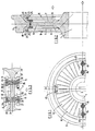
- the wheel constructed according to the present invention and illustrated in the accompanying drawings comprises a central hub 1 and an outer rim 3, interconnected by a web 5 which has two generally parallel, planar faces 7.
- a web 5 which has two generally parallel, planar faces 7.
- an annular brake disc 9 formed by two semi-circular segments 11.
- Each segment 11 is secured to the web 5 by a single gripping member 13 and a pair of resilient retaining connections 15 provided at each end edge region 17 of the segment 11. More gripping members 13 and a different number of resilient retaining connections 15 can be alternatively provided.
- each gripping member 13 comprises a hook-shaped member 19 which is bolted to the web 5 so that the hook-shaped end is hard against the outer rim 3 of the wheel.
- the hook-shaped end defines a part cylindrical recess 21 which extends generally circumferentially of the wheel, and an elongate cylindrical intermediate member 23 is engaged both in this part cylindrical recess 21 and in a like recess 25 in the outer periphery of the disc segment 11.
- each resilient retaining connection 15 comprises a roll pin 27 which is engaged through an aperture 29 in the web 5 so as to project from each side of the web 5 and engage with a curved surface 30 in an end edge 17 of the two disc segments 11 on each side of the web 5.
- the roll pin 27 comprises a hollow cylindrical member made of spring steel with a slot 31 cut completely through the wall of the pin and extending axially of the pin, for the full length of the pin; the slot 31 having a wavy profile.
- An end cap 33 is located over each end of each roll pin 27, the end caps 33 being secured to the roll pins by bolts 35 which extend axially through the roll pins.
- Each end cap 33 has an enlarged diameter portion in comparison with the roll pin and, in use, this enlarged diameter portion extends into a part cylindrical recess 37 provided in the end edge 17 of the disc segment 11. In this way the end edge regions 17 of the disc segments 11 are held to the web 5. Further each end cap 33 has a tongue 39 which extends into the end region of the slot 31 on the roll pin 27, to thus maintain the rotational position of the pin 27 with respect to the end edge regions of the disc segments 11; i.e. so that the slot 31 does not engage the end edge regions 17.
- the present invention thus provides a wheel with a braking disc mounted thereon, the disc being mounted in such a way that whilst it is positively retained, thermal expansion is allowed for and thus only minimal stresses are built up in the disc. This clearly extends the disc life and maintains required performance.
Landscapes
- Engineering & Computer Science (AREA)
- General Engineering & Computer Science (AREA)
- Mechanical Engineering (AREA)
- Braking Arrangements (AREA)
Claims (12)
Applications Claiming Priority (2)
| Application Number | Priority Date | Filing Date | Title |
|---|---|---|---|
| GB8521805 | 1985-09-03 | ||
| GB858521805A GB8521805D0 (en) | 1985-09-03 | 1985-09-03 | Wheel mounted discs |
Publications (2)
| Publication Number | Publication Date |
|---|---|
| EP0216534A1 EP0216534A1 (de) | 1987-04-01 |
| EP0216534B1 true EP0216534B1 (de) | 1989-12-20 |
Family
ID=10584611
Family Applications (1)
| Application Number | Title | Priority Date | Filing Date |
|---|---|---|---|
| EP19860306685 Expired EP0216534B1 (de) | 1985-09-03 | 1986-08-29 | Am Rad angeordnete Scheiben |
Country Status (6)
| Country | Link |
|---|---|
| EP (1) | EP0216534B1 (de) |
| AU (1) | AU589440B2 (de) |
| DE (1) | DE3667712D1 (de) |
| GB (1) | GB8521805D0 (de) |
| IN (1) | IN167591B (de) |
| NZ (1) | NZ217364A (de) |
Families Citing this family (7)
| Publication number | Priority date | Publication date | Assignee | Title |
|---|---|---|---|---|
| GB8521803D0 (en) * | 1985-09-03 | 1985-10-09 | Lucas Ind Plc | Wheel mounted discs |
| US4903801A (en) * | 1987-01-30 | 1990-02-27 | Jacob Kobelt | Segmented brake disc |
| US5101940A (en) * | 1989-11-07 | 1992-04-07 | Sab Sabco (Holdings) B.V. | Vehicle braking disc secured with an assembly of pine and blocks |
| GB9005421D0 (en) * | 1990-03-10 | 1990-05-09 | Lucas Ind Plc | Improvements relating to wheels incorporating brake discs |
| DE4143067A1 (de) * | 1991-12-27 | 1993-07-01 | Bergische Stahlindustrie | Gummigefedertes rad mit festmontierter bremsscheibe |
| FR2745349B1 (fr) * | 1996-02-28 | 1998-06-12 | Usines Dehousse | Disque de frein modulaire |
| US10259475B2 (en) * | 2014-02-12 | 2019-04-16 | Nippon Steel & Sumitomo Metal Corporation | Railway wheel with brake disc |
Family Cites Families (11)
| Publication number | Priority date | Publication date | Assignee | Title |
|---|---|---|---|---|
| DE1175721B (de) * | 1960-07-30 | 1964-08-13 | Bochumer Ver Fuer Gussstahlfab | Bremsscheibe insbesondere an Schienenrädern |
| DE1258444B (de) * | 1965-02-09 | 1968-01-11 | Krauss Maffei Ag | Radkoerper fuer Schienenfahrzeuge |
| DE2133235C3 (de) * | 1971-07-03 | 1979-09-27 | Kloeckner-Werke Ag, 4100 Duisburg | Radkörper-Bremsscheibe mit mindestens einem aus zwei Halbringen zusammengesetzten Bremsscheibenring, insbesondere für Schienenfahrzeuge |
| GB1478696A (en) * | 1973-10-15 | 1977-07-06 | Pont A Mousson | Assembly comprising a wheel and a disc brake disc in particular for a railway vehicle |
| DE2362904A1 (de) * | 1973-12-18 | 1975-06-26 | Bergische Stahlindustrie | Rad mit bremsscheiben ohne durchbrechung der radscheibe |
| GB1526204A (en) * | 1974-12-06 | 1978-09-27 | Girling Ltd | Disc brakes |
| GB1528126A (en) * | 1974-12-20 | 1978-10-11 | Girling Ltd | Disc brakes |
| CA1219818A (en) * | 1984-03-12 | 1987-03-31 | Roy E. Smith | Brake disc design for wheel mounted discs |
| DE3413843A1 (de) * | 1984-04-12 | 1985-10-17 | Knorr-Bremse GmbH, 8000 München | Befestigungsanordnung fuer bremsscheiben, insbesondere fuer schienenfahrzeuge |
| GB8521803D0 (en) * | 1985-09-03 | 1985-10-09 | Lucas Ind Plc | Wheel mounted discs |
| GB8521802D0 (en) * | 1985-09-03 | 1985-10-09 | Lucas Ind Plc | Wheel mounted discs |
-
1985
- 1985-09-03 GB GB858521805A patent/GB8521805D0/en active Pending
-
1986
- 1986-08-26 AU AU61870/86A patent/AU589440B2/en not_active Ceased
- 1986-08-27 NZ NZ21736486A patent/NZ217364A/en unknown
- 1986-08-28 IN IN688/MAS/86A patent/IN167591B/en unknown
- 1986-08-29 DE DE8686306685T patent/DE3667712D1/de not_active Expired - Lifetime
- 1986-08-29 EP EP19860306685 patent/EP0216534B1/de not_active Expired
Also Published As
| Publication number | Publication date |
|---|---|
| IN167591B (de) | 1990-11-17 |
| AU589440B2 (en) | 1989-10-12 |
| GB8521805D0 (en) | 1985-10-09 |
| AU6187086A (en) | 1987-03-05 |
| NZ217364A (en) | 1987-10-30 |
| EP0216534A1 (de) | 1987-04-01 |
| DE3667712D1 (de) | 1990-01-25 |
Similar Documents
| Publication | Publication Date | Title |
|---|---|---|
| EP0309174B1 (de) | Bremsscheibe für eine Scheibremse | |
| EP0944780B1 (de) | Scheibenbremsanlage | |
| US8474580B2 (en) | Floating brake disc | |
| CA1211386A (en) | Disc brake assembly | |
| EP0398092B1 (de) | Träger zur Drehmomentübertragung für Räder mit Bremsdrehmomentantrieb | |
| EP0360435B1 (de) | Scheibe für Fahrzeugscheibenbremsen | |
| GB2451880A (en) | Brake disc assembly the disc being quickly releasable from the wheel | |
| US4856619A (en) | Aircraft wheel drive key and heatshield assembly | |
| US5560452A (en) | Reinforcement device for carbon brake disks, and a brake disk fitted with such devices | |
| EP0447140B1 (de) | Verbesserungen beziehend auf Räder mit einverleibten Bremsscheiben | |
| WO2016014950A1 (en) | Brake disc and mounting arrangement | |
| EP0198217A1 (de) | Scheibenbremsmotor | |
| EP0453075B1 (de) | Räder mit eingebauten Bremsscheiben | |
| EP0216534A1 (de) | Am Rad angeordnete Scheiben | |
| WO2004063592A1 (en) | Brake disc assembly | |
| US5439077A (en) | Brake disk for wheel disk brakes | |
| EP0573236B1 (de) | Verbesserungen an Bremsscheiben | |
| EP0215597B1 (de) | Am Rad angeordnete Scheiben | |
| US4609078A (en) | Spring entrapment of split wedge floatation device | |
| EP0215598B1 (de) | Am Rad angeordnete Scheiben | |
| EP1408252B1 (de) | Mehrscheibenbremse | |
| EP0143941B1 (de) | Federhalterung für Schwimmsattel mit Führung durch geteilten Keil | |
| GB2187684A (en) | Split disc wheel for a vehicle | |
| EP0049187B1 (de) | Scheibenbremse | |
| GB2102744A (en) | Vehicle wheels |
Legal Events
| Date | Code | Title | Description |
|---|---|---|---|
| PUAI | Public reference made under article 153(3) epc to a published international application that has entered the european phase |
Free format text: ORIGINAL CODE: 0009012 |
|
| AK | Designated contracting states |
Kind code of ref document: A1 Designated state(s): DE FR GB IT |
|
| 17P | Request for examination filed |
Effective date: 19870502 |
|
| 17Q | First examination report despatched |
Effective date: 19880429 |
|
| GRAA | (expected) grant |
Free format text: ORIGINAL CODE: 0009210 |
|
| AK | Designated contracting states |
Kind code of ref document: B1 Designated state(s): DE FR GB IT |
|
| ITF | It: translation for a ep patent filed | ||
| REF | Corresponds to: |
Ref document number: 3667712 Country of ref document: DE Date of ref document: 19900125 |
|
| ET | Fr: translation filed | ||
| PLBE | No opposition filed within time limit |
Free format text: ORIGINAL CODE: 0009261 |
|
| 26N | No opposition filed | ||
| ITTA | It: last paid annual fee | ||
| REG | Reference to a national code |
Ref country code: GB Ref legal event code: 732 |
|
| REG | Reference to a national code |
Ref country code: FR Ref legal event code: TP |
|
| ITPR | It: changes in ownership of a european patent |
Owner name: CESSIONE;SAB WABCO HOLDINGS B.V. |
|
| PGFP | Annual fee paid to national office [announced via postgrant information from national office to epo] |
Ref country code: FR Payment date: 19930805 Year of fee payment: 8 |
|
| PGFP | Annual fee paid to national office [announced via postgrant information from national office to epo] |
Ref country code: GB Payment date: 19930819 Year of fee payment: 8 |
|
| PGFP | Annual fee paid to national office [announced via postgrant information from national office to epo] |
Ref country code: DE Payment date: 19930823 Year of fee payment: 8 |
|
| PG25 | Lapsed in a contracting state [announced via postgrant information from national office to epo] |
Ref country code: GB Effective date: 19940829 |
|
| GBPC | Gb: european patent ceased through non-payment of renewal fee |
Effective date: 19940829 |
|
| PG25 | Lapsed in a contracting state [announced via postgrant information from national office to epo] |
Ref country code: FR Effective date: 19950428 |
|
| PG25 | Lapsed in a contracting state [announced via postgrant information from national office to epo] |
Ref country code: DE Effective date: 19950503 |
|
| REG | Reference to a national code |
Ref country code: FR Ref legal event code: ST |
|
| PG25 | Lapsed in a contracting state [announced via postgrant information from national office to epo] |
Ref country code: IT Free format text: LAPSE BECAUSE OF NON-PAYMENT OF DUE FEES;WARNING: LAPSES OF ITALIAN PATENTS WITH EFFECTIVE DATE BEFORE 2007 MAY HAVE OCCURRED AT ANY TIME BEFORE 2007. THE CORRECT EFFECTIVE DATE MAY BE DIFFERENT FROM THE ONE RECORDED. Effective date: 20050829 |