EP0216540A1 - Leistungsgetriebe für Drehbewegungsübertragung - Google Patents
Leistungsgetriebe für Drehbewegungsübertragung Download PDFInfo
- Publication number
- EP0216540A1 EP0216540A1 EP86306758A EP86306758A EP0216540A1 EP 0216540 A1 EP0216540 A1 EP 0216540A1 EP 86306758 A EP86306758 A EP 86306758A EP 86306758 A EP86306758 A EP 86306758A EP 0216540 A1 EP0216540 A1 EP 0216540A1
- Authority
- EP
- European Patent Office
- Prior art keywords
- carriage
- ring gear
- chambers
- planetary gear
- passage
- Prior art date
- Legal status (The legal status is an assumption and is not a legal conclusion. Google has not performed a legal analysis and makes no representation as to the accuracy of the status listed.)
- Withdrawn
Links
Images


Classifications
-
- F—MECHANICAL ENGINEERING; LIGHTING; HEATING; WEAPONS; BLASTING
- F16—ENGINEERING ELEMENTS AND UNITS; GENERAL MEASURES FOR PRODUCING AND MAINTAINING EFFECTIVE FUNCTIONING OF MACHINES OR INSTALLATIONS; THERMAL INSULATION IN GENERAL
- F16H—GEARING
- F16H48/00—Differential gearings
- F16H48/20—Arrangements for suppressing or influencing the differential action, e.g. locking devices
- F16H48/27—Arrangements for suppressing or influencing the differential action, e.g. locking devices using internally-actuatable fluid pressure, e.g. internal pump types
-
- F—MECHANICAL ENGINEERING; LIGHTING; HEATING; WEAPONS; BLASTING
- F16—ENGINEERING ELEMENTS AND UNITS; GENERAL MEASURES FOR PRODUCING AND MAINTAINING EFFECTIVE FUNCTIONING OF MACHINES OR INSTALLATIONS; THERMAL INSULATION IN GENERAL
- F16D—COUPLINGS FOR TRANSMITTING ROTATION; CLUTCHES; BRAKES
- F16D31/00—Fluid couplings or clutches with pumping sets of the volumetric type, i.e. in the case of liquid passing a predetermined volume per revolution
- F16D31/04—Fluid couplings or clutches with pumping sets of the volumetric type, i.e. in the case of liquid passing a predetermined volume per revolution using gear-pumps
-
- F—MECHANICAL ENGINEERING; LIGHTING; HEATING; WEAPONS; BLASTING
- F16—ENGINEERING ELEMENTS AND UNITS; GENERAL MEASURES FOR PRODUCING AND MAINTAINING EFFECTIVE FUNCTIONING OF MACHINES OR INSTALLATIONS; THERMAL INSULATION IN GENERAL
- F16H—GEARING
- F16H3/00—Toothed gearings for conveying rotary motion with variable gear ratio or for reversing rotary motion
- F16H3/44—Toothed gearings for conveying rotary motion with variable gear ratio or for reversing rotary motion using gears having orbital motion
- F16H3/72—Toothed gearings for conveying rotary motion with variable gear ratio or for reversing rotary motion using gears having orbital motion with a secondary drive, e.g. regulating motor, in order to vary speed continuously
- F16H3/721—Toothed gearings for conveying rotary motion with variable gear ratio or for reversing rotary motion using gears having orbital motion with a secondary drive, e.g. regulating motor, in order to vary speed continuously the secondary drive being an energy dissipating device, e.g. regulating brake, in order to vary speed continuously
- F16H3/722—Toothed gearings for conveying rotary motion with variable gear ratio or for reversing rotary motion using gears having orbital motion with a secondary drive, e.g. regulating motor, in order to vary speed continuously the secondary drive being an energy dissipating device, e.g. regulating brake, in order to vary speed continuously the secondary drive being a fluid throttle
-
- F—MECHANICAL ENGINEERING; LIGHTING; HEATING; WEAPONS; BLASTING
- F16—ENGINEERING ELEMENTS AND UNITS; GENERAL MEASURES FOR PRODUCING AND MAINTAINING EFFECTIVE FUNCTIONING OF MACHINES OR INSTALLATIONS; THERMAL INSULATION IN GENERAL
- F16H—GEARING
- F16H48/00—Differential gearings
- F16H48/06—Differential gearings with gears having orbital motion
- F16H48/10—Differential gearings with gears having orbital motion with orbital spur gears
Definitions
- the present invention relates to variable speed transmission apparatus in clutches.
- Variable speed transmission apparatus including clutches, are generally complex and do not provide for a smooth transition between various speeds.
- Previously known apparatus due to their complexity, have been prone to failure and are generally expensive to manufacture and to maintain.
- variable speed transmission apparatus comprising an internal ring gear rotatable about a predetermined axis, a carriage also rotatable about the said axis, a planetary gear eccentrically mounted on said carriage and meshingly engaged with said ring gear so as to define a cavity to receive a working fluid, seal means mounted on said carriage and dividing said cavity to two chambers, passage means extending between said chambers and flow resistance means to adjustably inhibit the flow of hydraulic fluid between the two chambers upon relative rotation between the ring gear and carriage.
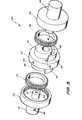
- FIG. 1 and 2 of the accompanying drawings there is schematically depicted a variable speed transmission apparatus 10.
- the apparatus 10 has an outer casing 11 which rotatably supports a ring gear shaft 13 fixed to a ring gear 23.
- a carriage 12 having a bearing passage 27.
- Rotatably supported in the passage 27 is a shaft 26 to which is attached a planetary gear 16.
- the carriage 12 rotates about the axis 14 together with the ring gear shaft 13.
- the planetary gear 16 rotates about an axis 15 eccentric relative to the shaft 14.
- the planetary gear 16 meshingly engages with the ring gear 23 and cooperates with the ring gear 23, carriage 12 and casing 11 to provide a generally enclosed cavity 28.
- the cavity 28 is generally sealingly divided into two chambers 24 and 25 by a sealing member 29.
- the sealing member 29 is fixed to the carriage 12 so as to rotate therewith together with the planetary gear 16.
- a clearance 30 Located within the cavity 28 and clearance 30 is a hydraulic fluid to be pumped between the two members 24 and 25 via the clearance 30.
- the cavity 28, together with the clearance 30 is filled with a working fluid.
- the working fluid is pumped between the chambers 24 and 25 by the planetary action of the gear 16.
- the planetary action of the gear 16 is governed by the variable resistance to the passage of the fluid through the clearance 30. If the carriage 12 is rotated, and there is very little resistance to the flow of fluid between the chambers 24 and 25, then the working fluid will freely move therebetween. In this particular configuration, little, if any at all, motion will be transferred to the shaft 13 from the carriage 12. If there is considerable resistance, or If untimately there is no fluid flow at all. then the speed of the carriage 12 would be the same as the speed of the shaft 13.
- the relative speeds of the casing 12 and shaft 13 may be varied by varying the clearance 30. Accordingly. if the shaft 13 (together with ring gear 23) is movable and/or the carriage 12, is movable then the clearance 30 may be adjusted to thereby adjust the resistance to the flow of the working fluid.
- the shaft 13 and/or the carriage 12 may be moved axially by means of a thrust bearing.
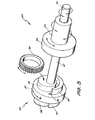
- FIGS 3, 4 and 5 there is schematically depicted a rotary power transmission assembly 30.
- a rotor assembly 30 coupling a pair of shafts 31 and 32.
- Fixed to each shaft is a ring gear 33 and 34 respectively which each meshingly engage with a planetary gear 35 and 36.
- a planetary gear carrier 37 having mounting spigots 38 and 39 which respectively rotatably support the planetary gears 35 and 36.
- sealing elements 40 Fixed to each shaft 31 and 32 is a carrier support spigot 41 which are received within a passage 42 formed in the carrier 37 so that the carrier 37 is rotatably supported by the spigots 41.
- a passage 43 which extends to the periphery of the carrier 37 at opening 44.
- a further passage 25 which communicates with a passage 46 in the carrier 37 terminating at opening 47 on a face of the carrier 37.
- a still further passage 48 Also extending between opposite sides of the carrier 37 is a still further passage 48.
- each planetary gear 35 or 36 cooperates with its associated ring gear 33 and sealing member 40 to provide a pair of spaced chambers between which fluid may be pumped by rotation of the respective ring gear 36 or 37 relative to and about the axis of its associated ring gear 33 or 34.
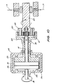
- the above described rotor assembly 30 is to be located in a housing 40 so as to form the transmission apparatus 50 of Figure 4.
- the housing 49 rotatably supports each shaft 31 and 32 and sealingly encompasses the rotor assembly 30. Additionally, the housing 49 is provided with sealing ridges 51 which are of annular configuration and provided with circular sealing elements 52.
- the ridges 51 cooperate to internally divide the housing 49 into a first chamber 53 and a second chamber 54.
- Formed in one of the ridges 51 is a valve assembly 55 consisting of a valve seat 56 which cooperates with a movable valve member 57.
- the movable valve member 57 allows selective fluid communication between the chambers 53 and 54.
- the passage 43 communicates with the chamber 54
- the passage 45 communicates with the chamber 53. Accordingly, there is a hydraulic circuit extending in a loop between the chambers 53 and 54 via the passages 45, 46, 48 and 43.
- the shaft 31 is driven, then rotary power is transmitted to the shaft 32 in accordance with the resistance to the flow of fluid between the two chambers 53 and 54.
- the movable valve member 57 closes the valve assembly 55, the rotor assembly 30 will rotate as a single unit so that the rotary speed of the shaft 31 will equal the rotary speed of the shaft 32.
- the movable valve member 57 allows direct communication between the chambers 53 and 54, then there will be relative rotation between the shafts 31 and 32. More particularly, if the shaft 31 is driven, and a load applied to the shaft 32, then rotary power will be transmitted between the shafts 31 and 32 according to the position of the movable valve member 57.
- the ring gear 33 When shaft 41 is driven, the ring gear 33 is caused to rotate about its central axis. This rotation of the ring gear 33 will cause rotation of the planetary gear 35 firstly about its own longitudinal axis. This rotation of the gear 35 will cause the working fluid to be pumped from one side of the carrier 37 to the other. This pumped fluid will then cause rotation of the planetary gear 36 which in turn will cause rotation of the ring gear 34.
- the passages 43, 46 and 48 may be arranged so that the direction of rotation of the shafts 31 and 32 is the same or in opposite directions.
- the differential assembly 60 of Figure 5 includes the rotor assembly 30 discussed with reference to Figures 3 and 4, however, the shaft 32 and spigot 41 are arranged for independent rotation.
- the rotor assembly 30 includes the carrier 37, and ring gear 34 fixed to the shaft 32.
- the spigot 41 described with reference to Figures 3 and 4 is replaced by a shaft 61 which extends through the ring gear 34 and shaft 32 so that the ring gear and shaft 32 are rotatably supported on the shaft 61. Accordingly, as the carrier 37 is also free to rotate, the shaft 32 and the shaft 61 can both be used as an output from the rotary input power applied to the shaft 31.
- Figure 6 there is schematically depicted a sectioned end elevation of the apparatus of Figure 6.
- the two chambers dividingly sealed by means of the sealing members 40 are more easily seen. More particularly, there is illustrated the two chambers 62 and 63 between which the working fluid is pumped.
- a brake means 64 which may be operated so as to selectively engage the carrier 37 so as to prevent rotation thereof.
- the carrier 37 if the carrier 37 is free to rotate then it will rotate with the shafts 31 and 32. If on the other hand, it is prevented from movement, the shafts 31 and 32 are caused to rotate in opposite directions.
- the ring gear 34 and its associated planetary gear 36 have been increased in width. Accordingly, for each revolution of the planetary gear 36 a greater amount of working fluid is pumped by the planetary gear 36. Accordingly, the rotational speed of the ring gear 34 will be less than the rotational speed of the ring gear 33 in proportion to the differences in width of the ring gears 33 and 34, assuming they have the same effective operating diameters.
- the shaft 32 is provided with a flared end 65 formed with a ring gear 66.
- the ring gear 66 meshingly engages a plurality of planetary gears 47 supported on a carrier 68 fixed to a shaft 79.
- the end of the shaft 32 is provided with a gear 70 which meshingly engages the planetary gears 67. Accordingly, there are two outputs from this assembly, one from the shaft 69 and the other from the shaft 32.
- a load 71 being applied to the shaft 69.
- the present invention in its preferred forms above, is suitable for inclusion in an automatic gear box assembly for a motor vehicle.
- Such an assembly would be of conventional construction apart from the rotor assembly 30, described previously, and is used in replacement of the traditional clutch assembly.
- the shaft 31 of the rotor assembly 30 would be coupled to the torque converter of the gear box assembly and the shaft 32 coupled to the tailshaft coupling of the gear box assembly.
Landscapes
- Engineering & Computer Science (AREA)
- General Engineering & Computer Science (AREA)
- Mechanical Engineering (AREA)
- Physics & Mathematics (AREA)
- Fluid Mechanics (AREA)
- Retarders (AREA)
- Structure Of Transmissions (AREA)
Applications Claiming Priority (2)
| Application Number | Priority Date | Filing Date | Title |
|---|---|---|---|
| AU226485 | 1985-09-03 | ||
| AU2264/85 | 1985-09-03 |
Publications (1)
| Publication Number | Publication Date |
|---|---|
| EP0216540A1 true EP0216540A1 (de) | 1987-04-01 |
Family
ID=3692779
Family Applications (1)
| Application Number | Title | Priority Date | Filing Date |
|---|---|---|---|
| EP86306758A Withdrawn EP0216540A1 (de) | 1985-09-03 | 1986-09-02 | Leistungsgetriebe für Drehbewegungsübertragung |
Country Status (2)
| Country | Link |
|---|---|
| EP (1) | EP0216540A1 (de) |
| JP (1) | JPS62132058A (de) |
Cited By (6)
| Publication number | Priority date | Publication date | Assignee | Title |
|---|---|---|---|---|
| EP0838606A3 (de) * | 1996-10-28 | 1998-09-30 | Tecumseh Products Company | Getriebe mit veränderbarem Übersetzungsverhältnis und Achsgetriebe |
| EP2141387A1 (de) * | 2008-05-14 | 2010-01-06 | Zaleski, Jacek | Stufenloses hydrostatisches Getriebe mit Drehbewegung |
| CN101658393A (zh) * | 2008-08-27 | 2010-03-03 | Seb公司 | 厨房器具盖 |
| EP2497950A1 (de) * | 2011-03-09 | 2012-09-12 | Volvo Car Corporation | Georotor Pumpe vorgesehen mit einem Steuerventil drehbar innerhalb der Welle. |
| US10731735B1 (en) * | 2018-03-19 | 2020-08-04 | Mainstream Engineering Corporation | Power transfer system and method using a variable speed ratio regulating device |
| WO2022214838A1 (en) * | 2021-04-07 | 2022-10-13 | Apergis Petros | Composite mechanical-hydraulic drive system with continuous variation of torque and speed from zero to maximum |
Families Citing this family (1)
| Publication number | Priority date | Publication date | Assignee | Title |
|---|---|---|---|---|
| CN109282008A (zh) * | 2018-11-26 | 2019-01-29 | 力源液压(苏州)有限公司 | 拖拉机及其齿轮箱 |
Citations (6)
| Publication number | Priority date | Publication date | Assignee | Title |
|---|---|---|---|---|
| US1828861A (en) * | 1930-03-29 | 1931-10-27 | Charles W De Hart | Hydraulic clutch |
| US2133276A (en) * | 1935-10-16 | 1938-10-18 | Robert L Ballantyne | Power transmission |
| US3234822A (en) * | 1963-07-29 | 1966-02-15 | Jay N Young | Hydraulically controlled positive infinitely variable transmission |
| GB1149124A (en) * | 1967-02-07 | 1969-04-16 | Vauxhall Motors Ltd | Differential gear assemblies |
| FR1580179A (de) * | 1968-03-14 | 1969-09-05 | ||
| DE2031508A1 (de) * | 1970-06-25 | 1971-12-30 | Eisenmann S | Hydrostatische Kupplung |
-
1986
- 1986-09-02 EP EP86306758A patent/EP0216540A1/de not_active Withdrawn
- 1986-09-02 JP JP61206661A patent/JPS62132058A/ja active Pending
Patent Citations (6)
| Publication number | Priority date | Publication date | Assignee | Title |
|---|---|---|---|---|
| US1828861A (en) * | 1930-03-29 | 1931-10-27 | Charles W De Hart | Hydraulic clutch |
| US2133276A (en) * | 1935-10-16 | 1938-10-18 | Robert L Ballantyne | Power transmission |
| US3234822A (en) * | 1963-07-29 | 1966-02-15 | Jay N Young | Hydraulically controlled positive infinitely variable transmission |
| GB1149124A (en) * | 1967-02-07 | 1969-04-16 | Vauxhall Motors Ltd | Differential gear assemblies |
| FR1580179A (de) * | 1968-03-14 | 1969-09-05 | ||
| DE2031508A1 (de) * | 1970-06-25 | 1971-12-30 | Eisenmann S | Hydrostatische Kupplung |
Cited By (12)
| Publication number | Priority date | Publication date | Assignee | Title |
|---|---|---|---|---|
| EP0838606A3 (de) * | 1996-10-28 | 1998-09-30 | Tecumseh Products Company | Getriebe mit veränderbarem Übersetzungsverhältnis und Achsgetriebe |
| US5860884A (en) * | 1996-10-28 | 1999-01-19 | Tecumseh Products Company | Variable speed transmission and transaxle |
| US5971881A (en) * | 1996-10-28 | 1999-10-26 | Tecumseh Products Company | Variable speed transmission and transaxle |
| AU730359B2 (en) * | 1996-10-28 | 2001-03-08 | Tecumseh Products Company | Variable speed transmission and transaxle |
| EP2141387A1 (de) * | 2008-05-14 | 2010-01-06 | Zaleski, Jacek | Stufenloses hydrostatisches Getriebe mit Drehbewegung |
| US20100186403A1 (en) * | 2008-05-14 | 2010-07-29 | Jacek Zaleski | Step-less hydrostatic gear box for rotary movement SLGB |
| US8402761B2 (en) * | 2008-05-14 | 2013-03-26 | Jacek Zaleski | Step-less hydrostatic gear box for rotary movement SLGB |
| CN101658393A (zh) * | 2008-08-27 | 2010-03-03 | Seb公司 | 厨房器具盖 |
| CN101658393B (zh) * | 2008-08-27 | 2013-11-06 | Seb公司 | 厨房器具盖 |
| EP2497950A1 (de) * | 2011-03-09 | 2012-09-12 | Volvo Car Corporation | Georotor Pumpe vorgesehen mit einem Steuerventil drehbar innerhalb der Welle. |
| US10731735B1 (en) * | 2018-03-19 | 2020-08-04 | Mainstream Engineering Corporation | Power transfer system and method using a variable speed ratio regulating device |
| WO2022214838A1 (en) * | 2021-04-07 | 2022-10-13 | Apergis Petros | Composite mechanical-hydraulic drive system with continuous variation of torque and speed from zero to maximum |
Also Published As
| Publication number | Publication date |
|---|---|
| JPS62132058A (ja) | 1987-06-15 |
Similar Documents
| Publication | Publication Date | Title |
|---|---|---|
| US3869940A (en) | Vehicle with differential assembly | |
| EP0004461A1 (de) | Stufenloses Getriebe | |
| US4109551A (en) | Variable speed gear ratio transmission apparatus | |
| GB1595124A (en) | Dual path dual range transmission | |
| CA2024560C (en) | Continuous speed-shifting device | |
| EP0216540A1 (de) | Leistungsgetriebe für Drehbewegungsübertragung | |
| JPS6363771B2 (de) | ||
| WO1994021940A1 (en) | Mechanical gearing | |
| EP0233303B1 (de) | Planetengetriebe | |
| JP3363163B2 (ja) | 可変ピッチプロペラ駆動装置 | |
| US4637275A (en) | Torque feedback transmission | |
| GB1597586A (en) | Variable speed transmission | |
| US4409862A (en) | Variable speed rotary power transmission | |
| US3788167A (en) | Multiple-speed transmission with reverse drive | |
| US6053840A (en) | Gear transmission with automatic continuously variable mechanical advantage | |
| US4630494A (en) | Radially oriented nutational traction drive transmission | |
| US4392395A (en) | Infinitely variable transmission | |
| US4194407A (en) | Variable speed transmission | |
| US5308293A (en) | Variable speed drive transmission | |
| US2330374A (en) | Power transmission | |
| US5624015A (en) | Infinitely variable positive gear ratio transmission | |
| CA2250476A1 (en) | Hydrostatic coupling comprising a planetary gear pump | |
| RU2085797C1 (ru) | Вариатор скорости | |
| KR950000045B1 (ko) | 무단자동 변속장치 | |
| JP2000065169A (ja) | 無段変速機 |
Legal Events
| Date | Code | Title | Description |
|---|---|---|---|
| PUAI | Public reference made under article 153(3) epc to a published international application that has entered the european phase |
Free format text: ORIGINAL CODE: 0009012 |
|
| AK | Designated contracting states |
Kind code of ref document: A1 Designated state(s): AT BE CH DE FR GB IT LI LU NL SE |
|
| STAA | Information on the status of an ep patent application or granted ep patent |
Free format text: STATUS: THE APPLICATION IS DEEMED TO BE WITHDRAWN |
|
| 18D | Application deemed to be withdrawn |
Effective date: 19871002 |
|
| RIN1 | Information on inventor provided before grant (corrected) |
Inventor name: HAAGE, DIETER |