EP0216562A2 - Dispositif de concentration d'énergie solaire et lentille de Fresnel mince et flexible - Google Patents
Dispositif de concentration d'énergie solaire et lentille de Fresnel mince et flexible Download PDFInfo
- Publication number
- EP0216562A2 EP0216562A2 EP86306943A EP86306943A EP0216562A2 EP 0216562 A2 EP0216562 A2 EP 0216562A2 EP 86306943 A EP86306943 A EP 86306943A EP 86306943 A EP86306943 A EP 86306943A EP 0216562 A2 EP0216562 A2 EP 0216562A2
- Authority
- EP
- European Patent Office
- Prior art keywords
- lens
- film
- target area
- solar radiation
- fresnel lens
- Prior art date
- Legal status (The legal status is an assumption and is not a legal conclusion. Google has not performed a legal analysis and makes no representation as to the accuracy of the status listed.)
- Granted
Links
Images


Classifications
-
- F—MECHANICAL ENGINEERING; LIGHTING; HEATING; WEAPONS; BLASTING
- F24—HEATING; RANGES; VENTILATING
- F24S—SOLAR HEAT COLLECTORS; SOLAR HEAT SYSTEMS
- F24S23/00—Arrangements for concentrating solar-rays for solar heat collectors
- F24S23/30—Arrangements for concentrating solar-rays for solar heat collectors with lenses
- F24S23/31—Arrangements for concentrating solar-rays for solar heat collectors with lenses having discontinuous faces, e.g. Fresnel lenses
-
- Y—GENERAL TAGGING OF NEW TECHNOLOGICAL DEVELOPMENTS; GENERAL TAGGING OF CROSS-SECTIONAL TECHNOLOGIES SPANNING OVER SEVERAL SECTIONS OF THE IPC; TECHNICAL SUBJECTS COVERED BY FORMER USPC CROSS-REFERENCE ART COLLECTIONS [XRACs] AND DIGESTS
- Y02—TECHNOLOGIES OR APPLICATIONS FOR MITIGATION OR ADAPTATION AGAINST CLIMATE CHANGE
- Y02E—REDUCTION OF GREENHOUSE GAS [GHG] EMISSIONS, RELATED TO ENERGY GENERATION, TRANSMISSION OR DISTRIBUTION
- Y02E10/00—Energy generation through renewable energy sources
- Y02E10/40—Solar thermal energy, e.g. solar towers
Definitions
- one such system has utilized concave, parabolic mirrors in the form of a large dish, as illustrated in U.S. Patent No. 4,111,184.
- other systems have utilized reflective troughs, as illustrated in U.S. Patent Nos. 4,385,430 and 4,211,211, or an array of concentric annular conic frusta, as illustrated in U.S. Patent No. 4,347,834.
- a system has used flat mirrored surfaces as illustrated in U.S. Patent No. 4,344,417 as well as flat fresnel mirrors, as illustrated in U.S. Patent No. 3,058,394.
- the reflective trough appeared to offer the best potential for high concentration of solar energy.
- this goal was seldom, if ever, achieved because of the precision required in the curvature of the reflective surface where any angular change at any point from the prescribed surface resulted in a two fold deviation of the reflected solar radiation.
- vibration of the reflecting surface could not be tolerated.
- the need to maintain the accuracy and steadiness of the reflecting surface over long periods of time required that the reflector be constructed of very rigid materials and be carefully aligned.
- a heavy and massive supporting structure was required.
- this massive structure had to be mounted so that it would remain vibration-free while tracking the sun in diurnal motion. Further, such structures have not been proved adaptable or feasible for use in space where weight reduction is of daunting importance.
- refractive lenses have been utilized. Examples of Fresnel-type lenses used to concentrate solar energy are illustrated in U.S. Patent Nos. 4,289,118; 4,194,949; and 4,011,857. In addition to the above, such lenses have also been utilized in the form of flat fresnel lenses, as illustrated in U.S. Patent Nos. 3,985,118 and 3,203,306, convex fresnel lenses, as illustrated in U.S. Patent No. 4,116,223, semi-cylindrical or tubular, as illustrated in U.S. Patent Nos. 4,299,201 and 3,125,091, or a linear array of refracting fresnel elements, as illustrated in U.S. Patent No. 4,069,812.
- the present invention affords an improved light weight refracting solar energy concentrator and thin flexible Fresnel-type lens which achieves and maintains high operational efficiencies with minimal weight and substantially reduced manufacturing cost.
- the structures simplicity of construction it can easily be deployed in space. Further, notwithstanding such simplicity of construction and its compactness, distortion of the refracting surface will not materially affect the efficiency of the concentrator, rendering the concentrator particularly advantageous for use in space.
- the invention described herein contemplates an improved solar energy concentrator, specifically, one in which a thin flexible Fresnel-type lens focuses incident solar radiation onto a target area by refraction.
- the fresnel lens is supported or suspended above the target area and folded along at least one line or region parallel to the refractive prisms of the lens which are generally parallel to the axis of the target area whereby the fresnel lens opens toward the target area.
- the efficiency of the concentrator is not materially affected by distortion of the fresnel lens when refraction by the thin film is substantially at minimum deviation.
- the fresnel lens is positioned above the target area so as to allow that portion or section of the lens between the folds to bow and flex under wind loads, gravity and other environmental factors without causing a significant deterioration in the efficiency of the system even though the surface of the fresnel lens may bow in and out from a planar position as much as 5° or more.
- the degree of bowing is conveniently measured as the angle between the plane in which the thin fresnel lens should lie and the tangent to the curve of the bow at the point of support.
- the material of which the fresnel lens consists is essentially a smooth flexible transparent polymeric material having a smooth surface and an opposite surface consisting of a plurality of miniature linear fresnel prisms or lenticular elements arranged side by side wherein the smooth surface effectively forms one of the optical faces of each prism.
- each prism includes an optical face which is intended to redirect the light.
- Each prism also has a nonactive optical face or step which does not block or interfere with the directed solar radiation.
- the prisms in the film are arranged such that the steps defined by the prisms do not interfere with the refraction of the incident solar radiation.
- the fresnel lens is oriented so that the more fragile fresnel prisms will not be directly exposed to hail, rain or other destructive environmental elements.
- the support structure which suspends the fresnel lens above the target area consists of struts or wires defining the aperture of the solar concentrator, and the fresnel lens is suspended on the struts or wires under slight tension.
- a center support extends along the center of the fresnel lens and is preferably removably supported by a spring biased shock absorber to apply a small force to the thin film to place it under a small but constant tension and to dampen severe repeated undulations. In this configuration, the fresnel lens can deflect under air pressure to maintain an acceptable performance.
- the target area upon which the solar radiation is focused can be black, opaque, translucent, or transparent and either pipes for transferring an absorptive media, or photovoltaic cells, etc. from which energy can be taken.
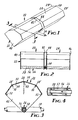
- the solar energy concentrator of the present invention includes a lightweight support structure or frame 22 and a linear echelon Fresnel-type lens 24 for focusing incident solar radiation onto a target area or absorber 26.
- the lens 24, which in this invention is a thin, limply flexible, transparent film, be folded at an acute angle to incident solar radiation (not normal) along at least one line or region 28 parallel to the refractive prisms of the lens which are generally parallel to the axis of the target area 26, and the film is suspended, drapped or mounted upon the support structure 22 to open toward the target area 26.
- the efficiency of the concentrator 20 is not materially affected by distortion of the lens 24.
- a solar energy concentrator 20 is depicted wherein the lens 24 is folded along three lines 28. It must be appreciated that the width and height (and corresponding focal length) of any given concentrator is a matter of choice dependant upon the given circumstances and the number of folds may therefor vary.
- the lens 24 consists of a thin, limply flexible, transparent sheet of polymeric material, for example, polymethylmethacrylate, having a smooth surface 30 on one side and a plurality of miniature linear fresnel prisms 32 extending lengthwise and arranged side by side to form the opposite or second surface 34, as illustrated in Figures 5A and 5B.
- the thin lens film 24 is very flexible and about 0.015 inch thick.
- the thin flexible fresnel lens 24, in a preferred embodiment, is positioned so that the smooth surface 30 is toward the sun, and the opposite surface 34 is toward the target area 26 to prevent the prisms 32 from being directly exposed to hail, rain and other destructive environmental elements.
- the film is easy to install, it can be conveniently replaced when soiled and/or damaged by the deleterious effects of the atmosphere and the elements.
- the prisms 32 on the film are arranged in such a manner that loss due to step interference caused by the nonactive face of the prisms is not in the way of light rays refracted by the optically active face of the prisms which is intended to bend the light toward the focus.
- the lens 24 is supported such that it is allowed to bow or flex transversely, axially or lengthwise to move toward and away from the target area 26.
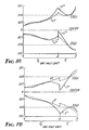
- the degree of bowing is conveniently measured as the angle between the plane in which the thin fresnel lens should lie and the tangent to the curve of the bow at the point of support, and the surface may bow in and out as much as 1°, 2°, 5° or more, without materially affecting the image quality of the lens.
- a negative bow of -1° or -2° would mean the lens would bow away from the target area, and a positive bow of +1° or +2° is toward the target area.
- one section or multiple sections located between the transversely placed supports may be used individually or in combination as a solar energy concentrator.
- the concentrator of solar energy of this invention can also be designed to focus the radiant energy onto a target or absorber which has a very small area and is essentially a spot or point.
- the sheet or lens 24 structured on one side with linearly arrayed discrete fresnel prisms 32 can be placed into close contact with another sheet or lens 24 ⁇ also structured on one side with an array of special discrete linear fresnel prisms 32 ⁇ disposed perpendicular to the first sheet 24, as illustrated in Figure 8.
- the first sheet can be structured on both sides.
- Another configuration consists of a structured sheet formed into a frustum and then topped with another sheet formed into a cone having a different angle than the frustum.
- This assembly of structured sheets will also focus the solar radiation onto a very small area, essentially a spot.
- the sheet of linearly arrayed fresnel prisms can also be cut into pie shaped triangles and fitted together to form a pyramid which configuration will also focus the incident solar radiation onto a spot.
- the long narrow target is an absorber pipe so constructed that the liquid heated by solar radiation leaves through the center of the absorber which consists of a pipe within a pipe.
- the unit is light weight it can be employed in most locations, especially where massive, cumbersome units are not suited. Because, in one embodiment, it can be rolled up into a small package it is especially well adapated for use in space. After the vehicle has been launched and is in orbit the solar concentrator, of this invention, can be automatically deployed. Precision alignment is not necessary for efficient operation.
Landscapes
- Engineering & Computer Science (AREA)
- Physics & Mathematics (AREA)
- Life Sciences & Earth Sciences (AREA)
- Sustainable Development (AREA)
- Sustainable Energy (AREA)
- Thermal Sciences (AREA)
- Chemical & Material Sciences (AREA)
- Combustion & Propulsion (AREA)
- Mechanical Engineering (AREA)
- General Engineering & Computer Science (AREA)
- Photovoltaic Devices (AREA)
- Optical Elements Other Than Lenses (AREA)
Applications Claiming Priority (2)
| Application Number | Priority Date | Filing Date | Title |
|---|---|---|---|
| US77404885A | 1985-09-09 | 1985-09-09 | |
| US774048 | 1985-09-09 |
Publications (3)
| Publication Number | Publication Date |
|---|---|
| EP0216562A2 true EP0216562A2 (fr) | 1987-04-01 |
| EP0216562A3 EP0216562A3 (en) | 1988-11-02 |
| EP0216562B1 EP0216562B1 (fr) | 1995-10-25 |
Family
ID=25100092
Family Applications (1)
| Application Number | Title | Priority Date | Filing Date |
|---|---|---|---|
| EP86306943A Expired - Lifetime EP0216562B1 (fr) | 1985-09-09 | 1986-09-09 | Dispositif de concentration d'énergie solaire et lentille de Fresnel mince et flexible |
Country Status (9)
| Country | Link |
|---|---|
| EP (1) | EP0216562B1 (fr) |
| JP (1) | JP2507712B2 (fr) |
| KR (1) | KR960016875B1 (fr) |
| CN (1) | CN1013457B (fr) |
| AU (1) | AU603772B2 (fr) |
| CA (1) | CA1286270C (fr) |
| DE (1) | DE3650426T2 (fr) |
| HK (1) | HK6897A (fr) |
| ZA (1) | ZA866820B (fr) |
Cited By (11)
| Publication number | Priority date | Publication date | Assignee | Title |
|---|---|---|---|---|
| EP0447600A1 (fr) * | 1990-03-23 | 1991-09-25 | Zeni Lite Buoy Co., Ltd. | Lentille cylindrique et méthode de fabrication pour cette lentille |
| WO1999017138A1 (fr) * | 1997-09-29 | 1999-04-08 | Eastman Kodak Company | Lentille flexible |
| US5932151A (en) * | 1997-09-29 | 1999-08-03 | Imation Corp. | Method of making a flexible lens |
| US6057537A (en) * | 1997-09-29 | 2000-05-02 | Eastman Kodak Company | Optical scanner feedback system having a reflected cylinder lens |
| US6094287A (en) * | 1998-12-03 | 2000-07-25 | Eastman Kodak Company | Wobble correcting monogon scanner for a laser imaging system |
| US6108025A (en) * | 1997-09-29 | 2000-08-22 | Eastman Kodak Company | Optical scanner system having a laser beam power attentuation mechanism |
| WO2001088444A1 (fr) * | 2000-05-15 | 2001-11-22 | Jaroslaw Szyrkowiec | Capteur d'energie solaire |
| WO2009106798A1 (fr) * | 2008-02-26 | 2009-09-03 | Microsharp Corporation Limited | Lentille prismatique |
| WO2015067966A3 (fr) * | 2013-11-08 | 2015-07-16 | Solar Steam Limited | Système de génération thermique à vapeur utilisant le rayonnement solaire |
| CN118655644A (zh) * | 2024-06-18 | 2024-09-17 | 大湾区大学(筹) | 太阳能吸收器及其加工方法 |
| US12619089B1 (en) * | 2024-10-22 | 2026-05-05 | Stephen Figlewski | Rainbow projector and method for producing rainbow light |
Families Citing this family (6)
| Publication number | Priority date | Publication date | Assignee | Title |
|---|---|---|---|---|
| US4545366A (en) * | 1984-09-24 | 1985-10-08 | Entech, Inc. | Bi-focussed solar energy concentrator |
| AU689873B2 (en) * | 1994-05-31 | 1998-04-09 | Sanyo Electric Co., Ltd. | Solar lighting apparatus and controller for controlling the solar lighting apparatus |
| CH699605A1 (de) * | 2008-09-30 | 2010-03-31 | Airlight Energy Ip Sa | Sonnenkollektor. |
| CN105403987A (zh) * | 2015-12-21 | 2016-03-16 | 九格能源科技(天津)有限公司 | 一种组合式太阳能聚光镜 |
| CN105403986A (zh) * | 2015-12-21 | 2016-03-16 | 九格能源科技(天津)有限公司 | 一种多焦点大口径太阳能聚光镜 |
| CN112762629B (zh) * | 2021-01-28 | 2021-12-17 | 华中科技大学 | 一种翼型线性菲涅尔聚光系统 |
Family Cites Families (9)
| Publication number | Priority date | Publication date | Assignee | Title |
|---|---|---|---|---|
| US3203306A (en) * | 1961-09-25 | 1965-08-31 | Lefferts Peter | Optical ray concentrator |
| US4210121A (en) * | 1977-06-15 | 1980-07-01 | Virgil Stark | Solar energy collection |
| CH630716A5 (en) * | 1978-05-03 | 1982-06-30 | Arthur Thyl Steinemann | Device for utilising the radiation energy of the sun |
| US4249516A (en) * | 1979-01-24 | 1981-02-10 | North American Utility Construction Corp. | Solar energy collection |
| NL7906145A (nl) * | 1979-08-13 | 1981-02-17 | Transformation Des Plastiques | Als lenzenstelsel werkend gebogen optisch paneel en met een dergelijk paneel uitgeruste inrichtingen voor het opvangen van zonneeenergie. |
| US4385808A (en) * | 1980-11-04 | 1983-05-31 | Minnesota Mining And Manufacturing Company | Point focus refracting radiation concentrator |
| JPS57151901A (en) * | 1981-03-16 | 1982-09-20 | Akira Nadaguchi | Fresnel condenser |
| JPS57157201A (en) * | 1981-03-24 | 1982-09-28 | Masao Horiguchi | Large-scal condensing member |
| US4545366A (en) * | 1984-09-24 | 1985-10-08 | Entech, Inc. | Bi-focussed solar energy concentrator |
-
1986
- 1986-07-31 CA CA000515066A patent/CA1286270C/fr not_active Expired - Lifetime
- 1986-08-06 AU AU60928/86A patent/AU603772B2/en not_active Ceased
- 1986-09-03 CN CN86105331A patent/CN1013457B/zh not_active Expired
- 1986-09-08 ZA ZA866820A patent/ZA866820B/xx unknown
- 1986-09-08 JP JP61211373A patent/JP2507712B2/ja not_active Expired - Lifetime
- 1986-09-08 KR KR1019860007488A patent/KR960016875B1/ko not_active Expired - Fee Related
- 1986-09-09 EP EP86306943A patent/EP0216562B1/fr not_active Expired - Lifetime
- 1986-09-09 DE DE3650426T patent/DE3650426T2/de not_active Expired - Lifetime
-
1997
- 1997-01-16 HK HK6897A patent/HK6897A/en not_active IP Right Cessation
Cited By (12)
| Publication number | Priority date | Publication date | Assignee | Title |
|---|---|---|---|---|
| EP0447600A1 (fr) * | 1990-03-23 | 1991-09-25 | Zeni Lite Buoy Co., Ltd. | Lentille cylindrique et méthode de fabrication pour cette lentille |
| WO1999017138A1 (fr) * | 1997-09-29 | 1999-04-08 | Eastman Kodak Company | Lentille flexible |
| US5932151A (en) * | 1997-09-29 | 1999-08-03 | Imation Corp. | Method of making a flexible lens |
| US6002524A (en) * | 1997-09-29 | 1999-12-14 | Imation Corp. | Flexible lens |
| US6057537A (en) * | 1997-09-29 | 2000-05-02 | Eastman Kodak Company | Optical scanner feedback system having a reflected cylinder lens |
| US6108025A (en) * | 1997-09-29 | 2000-08-22 | Eastman Kodak Company | Optical scanner system having a laser beam power attentuation mechanism |
| US6094287A (en) * | 1998-12-03 | 2000-07-25 | Eastman Kodak Company | Wobble correcting monogon scanner for a laser imaging system |
| WO2001088444A1 (fr) * | 2000-05-15 | 2001-11-22 | Jaroslaw Szyrkowiec | Capteur d'energie solaire |
| WO2009106798A1 (fr) * | 2008-02-26 | 2009-09-03 | Microsharp Corporation Limited | Lentille prismatique |
| WO2015067966A3 (fr) * | 2013-11-08 | 2015-07-16 | Solar Steam Limited | Système de génération thermique à vapeur utilisant le rayonnement solaire |
| CN118655644A (zh) * | 2024-06-18 | 2024-09-17 | 大湾区大学(筹) | 太阳能吸收器及其加工方法 |
| US12619089B1 (en) * | 2024-10-22 | 2026-05-05 | Stephen Figlewski | Rainbow projector and method for producing rainbow light |
Also Published As
| Publication number | Publication date |
|---|---|
| EP0216562A3 (en) | 1988-11-02 |
| CN86105331A (zh) | 1987-05-13 |
| KR870003360A (ko) | 1987-04-16 |
| CN1013457B (zh) | 1991-08-07 |
| ZA866820B (en) | 1988-04-27 |
| HK6897A (en) | 1997-01-24 |
| DE3650426D1 (de) | 1995-11-30 |
| AU6092886A (en) | 1987-03-12 |
| CA1286270C (fr) | 1991-07-16 |
| JPS6262155A (ja) | 1987-03-18 |
| DE3650426T2 (de) | 1996-06-27 |
| JP2507712B2 (ja) | 1996-06-19 |
| AU603772B2 (en) | 1990-11-29 |
| EP0216562B1 (fr) | 1995-10-25 |
| KR960016875B1 (ko) | 1996-12-23 |
Similar Documents
| Publication | Publication Date | Title |
|---|---|---|
| US4848319A (en) | Refracting solar energy concentrator and thin flexible Fresnel lens | |
| EP0216562B1 (fr) | Dispositif de concentration d'énergie solaire et lentille de Fresnel mince et flexible | |
| US7442871B2 (en) | Photovoltaic modules for solar concentrator | |
| CA1137372A (fr) | Systeme d'energie solaire muni d'une lentille convergente composite | |
| US4337759A (en) | Radiant energy concentration by optical total internal reflection | |
| US4344417A (en) | Solar energy collector | |
| US4120565A (en) | Prisms with total internal reflection as solar reflectors | |
| US4091798A (en) | Non-tracking solar energy collector system | |
| US4456783A (en) | Multielement optical panel | |
| US4003638A (en) | Radiant energy collection | |
| US4074704A (en) | Process of and apparatus for solar heating and the like | |
| US20090084374A1 (en) | Solar energy receiver having optically inclined aperture | |
| US20020075579A1 (en) | Apparatus for collecting and converting radiant energy | |
| US20120255540A1 (en) | Sun tracking solar concentrator | |
| US20070199563A1 (en) | Apparatus for concentration and conversion of solar energy | |
| JPH0262841B2 (fr) | ||
| Collares-Pereira | High temperature solar collector with optimal concentration: non-focusing Fresnel lens with secondary concentrator | |
| US4765726A (en) | Fresnel scroll solar tracking device | |
| Dang | Concentrators: a review | |
| US4124017A (en) | Collimating solar radiation collector | |
| US4471763A (en) | Solar energy concentrator | |
| US20090301469A1 (en) | Solar collectors | |
| US20100307480A1 (en) | Non-tracking solar collectors | |
| US4397302A (en) | Non-focusing solar energy concentrator | |
| JPH04171774A (ja) | 太陽電池装置 |
Legal Events
| Date | Code | Title | Description |
|---|---|---|---|
| PUAI | Public reference made under article 153(3) epc to a published international application that has entered the european phase |
Free format text: ORIGINAL CODE: 0009012 |
|
| AK | Designated contracting states |
Kind code of ref document: A2 Designated state(s): CH DE FR GB IT LI NL SE |
|
| PUAL | Search report despatched |
Free format text: ORIGINAL CODE: 0009013 |
|
| AK | Designated contracting states |
Kind code of ref document: A3 Designated state(s): CH DE FR GB IT LI NL SE |
|
| 17P | Request for examination filed |
Effective date: 19890502 |
|
| 17Q | First examination report despatched |
Effective date: 19891012 |
|
| GRAA | (expected) grant |
Free format text: ORIGINAL CODE: 0009210 |
|
| ITF | It: translation for a ep patent filed | ||
| AK | Designated contracting states |
Kind code of ref document: B1 Designated state(s): CH DE FR GB IT LI NL SE |
|
| PG25 | Lapsed in a contracting state [announced via postgrant information from national office to epo] |
Ref country code: CH Effective date: 19951025 Ref country code: LI Effective date: 19951025 Ref country code: NL Free format text: LAPSE BECAUSE OF FAILURE TO SUBMIT A TRANSLATION OF THE DESCRIPTION OR TO PAY THE FEE WITHIN THE PRESCRIBED TIME-LIMIT Effective date: 19951025 |
|
| REF | Corresponds to: |
Ref document number: 3650426 Country of ref document: DE Date of ref document: 19951130 |
|
| ET | Fr: translation filed | ||
| PG25 | Lapsed in a contracting state [announced via postgrant information from national office to epo] |
Ref country code: SE Effective date: 19960125 |
|
| NLV1 | Nl: lapsed or annulled due to failure to fulfill the requirements of art. 29p and 29m of the patents act | ||
| REG | Reference to a national code |
Ref country code: CH Ref legal event code: PL |
|
| PLBE | No opposition filed within time limit |
Free format text: ORIGINAL CODE: 0009261 |
|
| STAA | Information on the status of an ep patent application or granted ep patent |
Free format text: STATUS: NO OPPOSITION FILED WITHIN TIME LIMIT |
|
| 26N | No opposition filed | ||
| REG | Reference to a national code |
Ref country code: GB Ref legal event code: IF02 |
|
| PGFP | Annual fee paid to national office [announced via postgrant information from national office to epo] |
Ref country code: GB Payment date: 20050831 Year of fee payment: 20 |
|
| PGFP | Annual fee paid to national office [announced via postgrant information from national office to epo] |
Ref country code: FR Payment date: 20050919 Year of fee payment: 20 |
|
| PGFP | Annual fee paid to national office [announced via postgrant information from national office to epo] |
Ref country code: IT Payment date: 20050929 Year of fee payment: 20 |
|
| PGFP | Annual fee paid to national office [announced via postgrant information from national office to epo] |
Ref country code: DE Payment date: 20051031 Year of fee payment: 20 |
|
| PG25 | Lapsed in a contracting state [announced via postgrant information from national office to epo] |
Ref country code: GB Free format text: LAPSE BECAUSE OF EXPIRATION OF PROTECTION Effective date: 20060908 |
|
| REG | Reference to a national code |
Ref country code: GB Ref legal event code: PE20 |