EP0216571A2 - Sternabtastvorrichtung - Google Patents
Sternabtastvorrichtung Download PDFInfo
- Publication number
- EP0216571A2 EP0216571A2 EP86306982A EP86306982A EP0216571A2 EP 0216571 A2 EP0216571 A2 EP 0216571A2 EP 86306982 A EP86306982 A EP 86306982A EP 86306982 A EP86306982 A EP 86306982A EP 0216571 A2 EP0216571 A2 EP 0216571A2
- Authority
- EP
- European Patent Office
- Prior art keywords
- star
- star image
- photosensitive
- photosensitive elements
- optical system
- Prior art date
- Legal status (The legal status is an assumption and is not a legal conclusion. Google has not performed a legal analysis and makes no representation as to the accuracy of the status listed.)
- Withdrawn
Links
Images




Classifications
-
- G—PHYSICS
- G01—MEASURING; TESTING
- G01S—RADIO DIRECTION-FINDING; RADIO NAVIGATION; DETERMINING DISTANCE OR VELOCITY BY USE OF RADIO WAVES; LOCATING OR PRESENCE-DETECTING BY USE OF THE REFLECTION OR RERADIATION OF RADIO WAVES; ANALOGOUS ARRANGEMENTS USING OTHER WAVES
- G01S3/00—Direction-finders for determining the direction from which infrasonic, sonic, ultrasonic or electromagnetic waves, or particle emission, not having a directional significance, are being received
- G01S3/78—Direction-finders for determining the direction from which infrasonic, sonic, ultrasonic or electromagnetic waves, or particle emission, not having a directional significance, are being received using electromagnetic waves other than radio waves
- G01S3/782—Systems for determining direction or deviation from predetermined direction
- G01S3/789—Systems for determining direction or deviation from predetermined direction using rotating or oscillating beam systems, e.g. using mirrors, prisms
Definitions
- the present invention relates to a star scanner used for detecting the attitude of a space vehicle that is in a spinning motion in space.
- a conventional star scanner installed in a space vehicle comprises optical system 11 for forming an image of a star, a photoelectric transducer consisting of light-blocking plate 12 having a V-shaped (or N-shaped) slit pattern formed therein, and photomultiplier tube 13 located behind plate 12, and signal processor 14 for fetching the star image detection data from a signal output from photomultiplier 13. More particularly, as shown in Fig. 2A, a star image formed by optical system 11 is moved by the spinning of the vehicle and crosses slits Al and A2 of plate 12.
- the light passing through slits Al and A2 is detected by photomultiplier 13 and is transduced as a pulse signal having amplitude Is corresponding to its intensity, as shown in Fig. 2B.
- slits Al and A2 constitute a letter V (or N)
- two pulses (three pulses in the case of an N-shaped slit pattern) per star image are generated by photomultiplier 13.
- Pulse separation T of these pulses is determined in accordance with the positions at which the star image crosses slits Al and A2, i.e., the incident angle (angle of elevation) of the input light. Therefore, when amplitude Is and pulse separation T of the output pulses from photomultiplier 13 are measured by signal processor 14, the star can be identified and attitude of the vehicle can be deterned.
- the conventional star scanner uses a photomultiplier tube as an optical detector for its photoelectric transducer. Since the photomultiplier is a vacuum tube, it requires a high-voltage power supply of 1 to 2 kV, which leads to an increase in power consumption. In addition, since a photomultiplier tube is bulky and heavy, and has poor reliability, it poses many problems when it is installed on a satellite, whose maintenance is difficult to perform.
- another conventional star scanner uses, as an optical detector, a bar-type semiconductor photosensive element such as a photodiode.
- a bar-type semiconductor photosensive element such as a photodiode.
- two photodiodes are arranged to constitute a letter V (or N), in order to provide a small, lightweight, low-power optical detector.
- V or N
- a photodiode has a lower sensitivity than that of a photomultiplier tube and tends to be easily influenced by noise.
- a 1/f noise component of the photodiode has a power spectrum as shown in Fig. 3. As seen from Fig. 3, the 1/f noise component is very large in the low-frequency band and is a major factor causing noise.
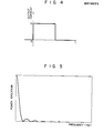
- the output current signal of the photodiode changes, as shown in Fig. 4.
- the power spectrum with respect to the frequency is as shown in Fig. 5 and major components thereof are concentrated in the low-frequency band.
- a conventional star scanner which uses a semiconductor photosensitive element, such as a photodiode, as an optical detector, the influence of the 1/f noise component is large, and only a star brighter than that of first magnitude can be detected.
- a star scanner comprising an optical system for forming a star image, a pair of semiconductor photosensitive elements constituting a letter V provided at a scanning section for the star image formed by said optical system, reticles, arranged between said optical system and each of said semiconductor photosensitive elements, for constituting a plurality of photosensitive sections and light-blocking sections on a photosensitive surface of each of said photosensitive elements along a star image scanning direction, and a signal processing section for generating detection data on the star image in accordance with an output signal from each of said semiconductor photosensitive elements.
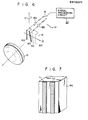
- Fig. 6 shows the overall arrangement of the embodiment of the present invention. More specifically, the star scanner of this embodiment comprises optical system 15 for forming a star image, photoelectric transducer 16 for photoelectric conversion of the light of the star image formed by optical system 15, and signal processor 17 for generating detection data of the formed star image based on the output signal of photoelectric transducer 16.
- Photoelectric transducer 16 uses four photodiodes (semiconductor photosensitive elements) 16a to 16d which are separated into two systems each constituting a letter V in the direction along which the star image formed by optical system 15 is scanned.
- a plurality of (two, in this case) reticles Ll and L2 are formed in direct contact with the photosensitive surface of each of photodiodes 16a to 16d along the longitudinal direction, so that a plurality of photosensitive sections and light-blocking sections are aligned at the same pitch in the star image scanning direction, as shown in Fig. 7.
- Signal processor 17 consists of amplifier 18 for amplifying the outputs from the two systems of photoelectric transducer 16, switch 19 for selective output of an arbitrary output of the two systems of amplifier 18, and signal processing circuit 20 for receiving the signal output from switch 19 and for generating detection data on the star image.
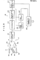
- Fig. 8 is a block circuit diagram of the practical arrangement of signal processor 17.
- the signals obtained by photodiodes 16a to 16d of photoelectric transducer 16 are grouped in accordance with the systems, amplified by preamplifiers 18a and 18b of amplifier 18, and selectively supplied to signal processing circuit 20 by switch 19.
- preamplifiers 18a and 18b of amplifier 18 are selectively supplied to signal processing circuit 20 by switch 19.
- circuit 20 only a frequency signal of a predetermined band is derived from the input signal, by band-pass filter 201.
- the frequency signal is converted into a pulse train signal by discriminator 202 and is shaped to a single pulse signal by waveshaping circuit 203.
- the trailing time of the pulse signal output from circuit 203 is detected by clock-generating circuit 204 and is fed to telemetry interface 205, as detection time data of the star image.
- Peak-hold circuit 206 detects the peak value of the frequency signal derived by filter 201 during the pulse output period of circuit 203.
- the peak value is converted to a digital signal by analog/digital conversion (ADC) circuit 207 and is fed to interface 205, as amplitude data.
- ADC analog/digital conversion
- the time data and the amplitude data input to interface 205 are paired and sent to a attitude control circuit (not shown) or the like, of the vehicle.
- FIG. 9 denotes the amplitude of the output signal from photodiode 16a, which is generally expressed as: where ⁇ is the efficiency of optical system 15, S( ⁇ ) is the illuminance spectrum of the star, and R( ⁇ ) is the sensitivity of photodiode 16a.
- Ts denotes a pulse width. Pulse width Ts is expressed as: where Rs [rpm] is the spin rate of the vehicle, d is the distance between reticles Ll and L2, and fd is the focal length of optical system 15.
- the waveform of output current signal I(t) is expressed as:
- the power spectrum of signal I(t) is expressed as:
- the typical frequency of signal I(t) becomes 1/2Ts [Hz] by means reticles Ll and L2 provided on photodiode 16a, and the major components of signal I(t) are concentrated around this frequency.
- the basic frequency can be maximized when the distances between the photosensitive sections and the light-blocking sections of photodiode 16a are set equal. Meanwhile, the 1/f noise component in the vicinity of this frequency is quite small when compared to the fundamental frequency component.
- the S/N ratio after passing through filter 201 is expressed as:
- the S/N ratio is expressed as: From equations (6) and (7), when a star scanner with reticles is used, the S/N ratio is about 5.6 times that of the star scanner without reticles, and a star of about third magnitude can be detected.
- Fig. 11 shows the relationship between the spin rate and the S/N ratio of this case.
- the present invention is not limited to the above embodiment.
- the number, width, and interval of the reticles provided on the photodiode can be arbitrarily selected.
- the widths of the photosensitive sections and the light-blocking sections of the photodiode constituted by the reticles are the same, the power spectrum of the fundamental frequency component becomes maximum.
- the number of reticles per unit width is increased to increase the number of the light-receiving and light-blocking sections, the fundamental frequency of the signal is increased, resulting in a good S/N ratio.
- the widths of the photosensitive and light-blocking sections must be determined in consideration of the size of the star image, depending on the chracteristics of the optical system.
- the scanning width of the photodiode is increased to increase the number of reticles, the fundamental frequency component of the power spectrum is increased. In this case, however, the longer the width of the photodiode, the worse the precision of the angular resolution.
- the width of the photodiode and the width and the number of the reticles must be determined in consideration of the above conditions, so that an optimal design can be obtained.
- the reticles need not be arranged in direct contact with the photodiode, but can be spaced apart from the photodiode.
- the reticles need not be formed in separate groups, but can be formed in a slit-like manner.
- two signal detection systems i.e., photodiode pair and preamplifire
- another redundant signal detection system can be added for further increasing the reliability.
- the photodiodes to be used can be freely selected.
- the semiconductor photosensitive element is not limited to the photodiode but can be a photoconductor, phototransistor, a CCD, or the like.
Landscapes
- Physics & Mathematics (AREA)
- Electromagnetism (AREA)
- Engineering & Computer Science (AREA)
- General Physics & Mathematics (AREA)
- Radar, Positioning & Navigation (AREA)
- Remote Sensing (AREA)
- Navigation (AREA)
Applications Claiming Priority (2)
| Application Number | Priority Date | Filing Date | Title |
|---|---|---|---|
| JP200860/85 | 1985-09-11 | ||
| JP60200860A JPH061197B2 (ja) | 1985-09-11 | 1985-09-11 | スタ−スキヤナ |
Publications (2)
| Publication Number | Publication Date |
|---|---|
| EP0216571A2 true EP0216571A2 (de) | 1987-04-01 |
| EP0216571A3 EP0216571A3 (de) | 1987-11-25 |
Family
ID=16431423
Family Applications (1)
| Application Number | Title | Priority Date | Filing Date |
|---|---|---|---|
| EP86306982A Withdrawn EP0216571A3 (de) | 1985-09-11 | 1986-09-10 | Sternabtastvorrichtung |
Country Status (3)
| Country | Link |
|---|---|
| US (1) | US4703167A (de) |
| EP (1) | EP0216571A3 (de) |
| JP (1) | JPH061197B2 (de) |
Cited By (1)
| Publication number | Priority date | Publication date | Assignee | Title |
|---|---|---|---|---|
| WO2023163689A1 (en) * | 2022-02-28 | 2023-08-31 | Roketsan Roket Sanayi̇i̇ Ti̇caret A.Ş. | Star-shaped scanning system and method |
Families Citing this family (8)
| Publication number | Priority date | Publication date | Assignee | Title |
|---|---|---|---|---|
| JPH02236108A (ja) * | 1989-03-09 | 1990-09-19 | Toshiba Corp | 太陽センサ |
| US5091637A (en) * | 1989-08-11 | 1992-02-25 | Loral Aerospace Corp. | Noise reducing infrared reticle/detector arrangement |
| US4967065A (en) * | 1989-08-11 | 1990-10-30 | Ford Aerospace Corporation | Integrated reticle and detector |
| JPH03226624A (ja) * | 1990-01-31 | 1991-10-07 | Nec Corp | スタースキャナ |
| JP2591232B2 (ja) * | 1990-03-16 | 1997-03-19 | 日本電気株式会社 | スピンレート追従型スター・スキャナ |
| GB9015945D0 (en) * | 1990-07-20 | 1990-09-05 | Gorham Barry J | Method and apparatus for measurement of direction |
| GB9113494D0 (en) * | 1991-06-21 | 1991-08-07 | Gorham Barry J | Method and apparatus for measurement of direction |
| US5355222A (en) * | 1992-05-15 | 1994-10-11 | Precision Tracking Fm, Inc. | Optical receiver for area location system |
Family Cites Families (12)
| Publication number | Priority date | Publication date | Assignee | Title |
|---|---|---|---|---|
| US2981842A (en) * | 1953-09-01 | 1961-04-25 | Northrop Corp | Automatic grid scanning tracker |
| NL278853A (de) * | 1961-05-25 | |||
| US3357298A (en) * | 1963-06-19 | 1967-12-12 | North American Aviation Inc | Star tracker including angularly disposed photoelectric strip surfaces |
| US3388629A (en) * | 1963-11-07 | 1968-06-18 | Gen Precision Inc | Detection means for star tracker |
| US3609374A (en) * | 1967-02-24 | 1971-09-28 | Singer General Precision | Weighted scan star scanner |
| US3515594A (en) * | 1967-12-21 | 1970-06-02 | Trw Inc | Radiant energy driven orientation system |
| US3612701A (en) * | 1969-01-09 | 1971-10-12 | Singer General Precision | Light-detecting system |
| US3614239A (en) * | 1970-04-21 | 1971-10-19 | Us Air Force | Photoelectric space-object position measuring device |
| US3739175A (en) * | 1971-01-06 | 1973-06-12 | Honeywell Inc | Photo sensitive star sensing array |
| US3827807A (en) * | 1972-09-29 | 1974-08-06 | Nasa | Star scanner |
| GB1550339A (en) * | 1975-08-28 | 1979-08-15 | Elliott Brothers London Ltd | Optical angular position sensors |
| US4627724A (en) * | 1983-07-08 | 1986-12-09 | The United States Of America As Represented By The Secretary Of The Army | Radiation scanning and detection system |
-
1985
- 1985-09-11 JP JP60200860A patent/JPH061197B2/ja not_active Expired - Lifetime
-
1986
- 1986-09-05 US US06/903,764 patent/US4703167A/en not_active Expired - Lifetime
- 1986-09-10 EP EP86306982A patent/EP0216571A3/de not_active Withdrawn
Cited By (1)
| Publication number | Priority date | Publication date | Assignee | Title |
|---|---|---|---|---|
| WO2023163689A1 (en) * | 2022-02-28 | 2023-08-31 | Roketsan Roket Sanayi̇i̇ Ti̇caret A.Ş. | Star-shaped scanning system and method |
Also Published As
| Publication number | Publication date |
|---|---|
| JPH061197B2 (ja) | 1994-01-05 |
| EP0216571A3 (de) | 1987-11-25 |
| US4703167A (en) | 1987-10-27 |
| JPS6259809A (ja) | 1987-03-16 |
Similar Documents
| Publication | Publication Date | Title |
|---|---|---|
| US6154551A (en) | Microphone having linear optical transducers | |
| EP0336152A1 (de) | Optischer Sensor zur Richtungsbestimmung eintreffender Strahlung | |
| US4703167A (en) | Star scanner with semiconductor photosensitive elements having reticles | |
| US4728804A (en) | Scanning system with low sampling rate | |
| EP1206131A4 (de) | Halbleiterbildaufnahme- und abstandsermittlungsvorrichtung | |
| TW349011B (en) | Remote position sensing apparatus and method | |
| JPH0376428B2 (de) | ||
| CA1068371A (en) | Circuit arrangements for controlling detector signals in surface inspection systems | |
| CA2386332C (en) | System for tracking angular and linear motion | |
| GB2180930A (en) | Optical web-monitoring apparatus | |
| US5386123A (en) | Beam steering sensor for a raster scanner using a lateral effect detecting device | |
| US5276323A (en) | Optical movement detector detecting a position of an optical gravity center | |
| US4710816A (en) | Picture signal generating apparatus | |
| JP3201648B2 (ja) | 同期検出装置 | |
| Eliot | Geometric design of linear array detectors | |
| SU1643993A1 (ru) | Устройство дл измерени размеров и числа частиц в жидкости | |
| EP0312156B1 (de) | Röntgenliniendetektor-Anordnung sowie ein mit einer derartigen Anordnung ausgerüstetes Röntgenanalysegerät | |
| JP3404173B2 (ja) | スタースキャナ | |
| SU956063A1 (ru) | Способ сепарации руды и устройство дл его осуществлени | |
| JPH04247761A (ja) | 同期検出回路 | |
| JP3023157B2 (ja) | 太陽センサの光入射位置検出装置 | |
| US6744940B2 (en) | Sensor for a receiving device for cooperation with an optical fiber | |
| JPH02240515A (ja) | 位置検出装置 | |
| JP2699731B2 (ja) | スタースキャナ | |
| JPS62238402A (ja) | 磁気テ−プ走行位置検出センサ |
Legal Events
| Date | Code | Title | Description |
|---|---|---|---|
| PUAI | Public reference made under article 153(3) epc to a published international application that has entered the european phase |
Free format text: ORIGINAL CODE: 0009012 |
|
| 17P | Request for examination filed |
Effective date: 19860926 |
|
| AK | Designated contracting states |
Kind code of ref document: A2 Designated state(s): DE FR GB IT |
|
| PUAL | Search report despatched |
Free format text: ORIGINAL CODE: 0009013 |
|
| AK | Designated contracting states |
Kind code of ref document: A3 Designated state(s): DE FR GB IT |
|
| 17Q | First examination report despatched |
Effective date: 19900720 |
|
| STAA | Information on the status of an ep patent application or granted ep patent |
Free format text: STATUS: THE APPLICATION IS DEEMED TO BE WITHDRAWN |
|
| 18D | Application deemed to be withdrawn |
Effective date: 19921209 |
|
| RIN1 | Information on inventor provided before grant (corrected) |
Inventor name: TSUNO, KATSUHIKOC/O PATENT DIVISION Inventor name: OKUMURA, EISUKEC/O PATENT DIVISION |