EP0216578A2 - Ergonomische Körperstütze - Google Patents
Ergonomische Körperstütze Download PDFInfo
- Publication number
- EP0216578A2 EP0216578A2 EP86307015A EP86307015A EP0216578A2 EP 0216578 A2 EP0216578 A2 EP 0216578A2 EP 86307015 A EP86307015 A EP 86307015A EP 86307015 A EP86307015 A EP 86307015A EP 0216578 A2 EP0216578 A2 EP 0216578A2
- Authority
- EP
- European Patent Office
- Prior art keywords
- support members
- supporting portion
- lumbar
- posterior
- support
- Prior art date
- Legal status (The legal status is an assumption and is not a legal conclusion. Google has not performed a legal analysis and makes no representation as to the accuracy of the status listed.)
- Ceased
Links
Images


Classifications
-
- A—HUMAN NECESSITIES
- A47—FURNITURE; DOMESTIC ARTICLES OR APPLIANCES; COFFEE MILLS; SPICE MILLS; SUCTION CLEANERS IN GENERAL
- A47C—CHAIRS; SOFAS; BEDS
- A47C7/00—Parts, details, or accessories of chairs or stools
- A47C7/36—Supports for the head or the back
- A47C7/40—Supports for the head or the back for the back
- A47C7/44—Supports for the head or the back for the back with elastically-mounted frame
-
- A—HUMAN NECESSITIES
- A47—FURNITURE; DOMESTIC ARTICLES OR APPLIANCES; COFFEE MILLS; SPICE MILLS; SUCTION CLEANERS IN GENERAL
- A47C—CHAIRS; SOFAS; BEDS
- A47C3/00—Chairs characterised by structural features; Chairs or stools with rotatable or vertically-adjustable seats
-
- A—HUMAN NECESSITIES
- A47—FURNITURE; DOMESTIC ARTICLES OR APPLIANCES; COFFEE MILLS; SPICE MILLS; SUCTION CLEANERS IN GENERAL
- A47C—CHAIRS; SOFAS; BEDS
- A47C7/00—Parts, details, or accessories of chairs or stools
- A47C7/02—Seat parts
- A47C7/024—Seat parts with double seats
-
- A—HUMAN NECESSITIES
- A47—FURNITURE; DOMESTIC ARTICLES OR APPLIANCES; COFFEE MILLS; SPICE MILLS; SUCTION CLEANERS IN GENERAL
- A47C—CHAIRS; SOFAS; BEDS
- A47C7/00—Parts, details, or accessories of chairs or stools
- A47C7/02—Seat parts
- A47C7/029—Seat parts of non-adjustable shape adapted to a user contour or ergonomic seating positions
-
- A—HUMAN NECESSITIES
- A47—FURNITURE; DOMESTIC ARTICLES OR APPLIANCES; COFFEE MILLS; SPICE MILLS; SUCTION CLEANERS IN GENERAL
- A47C—CHAIRS; SOFAS; BEDS
- A47C7/00—Parts, details, or accessories of chairs or stools
- A47C7/02—Seat parts
- A47C7/16—Seats made of wooden, plastics, or metal sheet material; Panel seats
-
- A—HUMAN NECESSITIES
- A47—FURNITURE; DOMESTIC ARTICLES OR APPLIANCES; COFFEE MILLS; SPICE MILLS; SUCTION CLEANERS IN GENERAL
- A47C—CHAIRS; SOFAS; BEDS
- A47C7/00—Parts, details, or accessories of chairs or stools
- A47C7/36—Supports for the head or the back
- A47C7/40—Supports for the head or the back for the back
- A47C7/405—Supports for the head or the back for the back with double backrests
-
- A—HUMAN NECESSITIES
- A47—FURNITURE; DOMESTIC ARTICLES OR APPLIANCES; COFFEE MILLS; SPICE MILLS; SUCTION CLEANERS IN GENERAL
- A47C—CHAIRS; SOFAS; BEDS
- A47C7/00—Parts, details, or accessories of chairs or stools
- A47C7/36—Supports for the head or the back
- A47C7/40—Supports for the head or the back for the back
- A47C7/46—Supports for the head or the back for the back with special, e.g. adjustable, lumbar region support profile; "Ackerblom" profile chairs
Definitions
- the present invention relates in general to an ergonomic support in the nature of chairs, sofas and the like, and more particularly, to such an ergonomic support having posterior and/or lumbar supporting portions which automatically conform to body movement without mechanical parts, as opposed to adjusting the body to comfortably conform to the posterior and lumbar supporting portions.
- the posterior and/or lumbar supporting portions include non-planar contoured supporting surfaces shaped as compound curves, i.e., three-dimensional, thereby providing an effective ergonomic support for different body positions.
- chairs and sofas are known to be constructed from posterior and lumbar supporting assemblies consisting generally of a frame having a plurality of springs, a cushion or pad which rests on the springs, and an upholstery cover. These assemblies, although flexible due to their spring construction, assume a predetermined fixed shape which requires that man adjust his body position relative to these assemblies for maximum comfort.
- posterior and lumbar supporting assemblies consisting generally of a frame having a plurality of springs, a cushion or pad which rests on the springs, and an upholstery cover.
- an ergonomic support including a posterior supporting portion and a lumbar supporting portion, at least one of said supporting portions comprising a first shell portion having an inner member and an outer member, and the inner member includes a plurality of first support members formed from a portion of the inner member, said support members joined together to individually and cooperatively provide flexible support for a supported region of a person so that the support members conform to the supported region for different body positions.
- an ergonomic support including a posterior supporting portion and a lumbar supporting portion, said lumbar supporting portion including a plurality of first support members joined together to individually and cooperatively provide flexible support for the lumbar region of a person, said first support members each having a rear surface and a lumbar supporting front surface, and the front surface has portions extending outwardly varying distances from a common reference plane such that the support members conform to the lumbar region of a person for different body positions.
- an ergonomic support including a lumbar supporting portion and a posterior supporting portion, at least one of said portions including a first non-planar member having a contoured body supporting surface, and a plurality of first support members forming at least a portion of the non-planar member, said support members being joined together to individually and cooperatively provide flexible support for a supported region of a person so that the said support members conform to the supported region for different body positions.
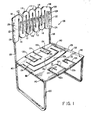
- FIG. 1 a perspective view of an ergonomic chair constructed in accordance with the present invention and designated generally by reference numeral 100.
- the chair 100 is generally constructed of a posterior supporting portion 102, i.e., chair bottom, a lumbar supporting portion 104, i.e., chair back, and a supporting frame 106 having upstanding spaced-apart side frame members 108.
- the posterior supporting portion 102 and lumbar supporting portion 104 may be constructed from a variety of material, for example, wood, metal, aluminum, plastic, and the like.
- the lumbar supporting portion 104 is constructed from a plurality of support members 110a-110h arranged adjacent one another and joined together to individually and cooperatively provide flexible support to the lumbar region of a person.
- the support members 110a-110h are joined together to provide a plurality of upwardly extending cantilevers 112 and a plurality of downwardly extending cantilevers 113 joined together in serpentine or sinusoidal shape.
- Each upwardly extending cantilever 112 is formed, for example, from a pair of adjacent support members 110d, 110e joined together at one common end 114 and supported at their other common end 116 by adjacent support members.110c, 110f.
- Each downwardly extending cantilever 113 is constructed in a similar manner.
- each upwardly extending cantilever 11 2 contains a common support member 110a-110h with an adjacent downwardly extending cantilever 113.
- the single row of support members llOa-110h is supported at opposite ends thereof by connection to a pair of end joining members 118.
- the cantilevers 112, 113 are formed by cutting, in the case of wood or metal, and molding, in the case of plastic, a plurality of parallel spaced-apart elongated openings 120 to define the individual support members l10a-110h.
- the openings 120 provide the lumbar supporting portion 104 with the resiliency and flexibility necessary to allow each of the support members 110a-110h to function in a manner to independently and cooperatively support the lumbar portion of a person, notwithstanding the rigid properties of their material of construction.
- the openings 120 are dimensioned such that the ratio of the width of the openings to the width of an adjacent support member 110a-110h is in the range of about 1:4 to 1:11. Preferably, such ratio is in the range of about 1:4 to 1:5.
- the lumbar supporting portion 104 is pivotally attached about pivot points 122, located on the end joining members 118, to the side frame members 108.
- the foregoing construction of the lumbar supporting portion 104 and its pivotal attachment to the side frame members 108 allows the support members l10a-110h, and thus formed cantilevers 112, 113, to individually and cooperatively provide flexible support for the lumbar region of a person.
- the lumbar supporting portion 104 becomes totally flexible, allowing twisting and tilting of the individual support members 110a-110h, and thus formed cantilevers 112, 113, in a manner which continuously adjusts and conforms to the lumbar region of a person.
- the lumbar supporting portion 104 may be attached to the side frame members 108 by means of two spaced-apart connecting points 124 located on the end joining members 118.
- the location of the pivot point 122, with respect to the longitudinal and transverse axes of the end joining members 118, may be varied to effect the degree and nature of twisting of the lumbar supporting portion 104.
- individual support members 110a-110h may be constructed of different cross-sectional areas, i.e., thicknesses, to provide varying degrees of flexibility and resiliency to the lumbar supporting portion 104.
- the support members 110a-110h may be laminated with composite materials having different resiliency and flexibility characteristics in order to profile the flexing properties of the lumbar supporting portion 104.
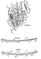
- FIGS. 2 and 3 there is shown two additional embodiments of the lumbar supporting portion 104 constructed in accordance with the present invention.
- the support members 110 and thus formed cantilevers 112, 113, have a generally rectangular shape, as opposed to the rounded shape in accordance with the embodiment disclosed in FIG. 1.
- the ratio of the width of the elongated opening 120 to the width of an adjacent support member 110 is about 1:11, whereas the ratio in the embodiment of FIG. 1 is about 1:4.
- This construction results in the lumbar supporting portion 104, as disclosed in FIG. 2, being less flexible than the lumbar supporting portion constructed in accordance with the embodiment disclosed in FIG. 1.
- the lumbar supporting portion 104 is provided with an upper row of support members 110 and a lower row of support members 11 0'.
- the cross-sectional area and/or material of construction of the individual support members 110, 110' can be varied to provide the lumbar supporting portion 104 with varying degrees of flexibility and resiliency as desired.
- the lumbar supporting portion 104 is constructed to include an upper row of support members 110 and a lower row of support members 110' in accordance with the embodiment disclosed in FIG. 3.
- the outer lumbar supporting surfaces 126, 126' of the upper row of support members 110 and lower row of support members 110' are formed as a compound curved surface.
- the outer lumbar supporting surfaces 126, 126' are three-dimensional, by being non-planar, contoured front surfaces, thereby providing an effective ergonomic support.
- the outer lumbar supporting surfaces 126, 126' have various portions thereof extending outwardly varying distances from a common reference plane 128, e.g., rear surfaces 127, 127'.
- the outer lumbar supporting surface 126 tapers outwardly from end 114 towards end 116 of the cantilevers 112, 113. This results from the support members 110 having a generally wedge-shaped cross-section.
- the outer lumbar supporting surface 126' of the support members 110' is curved outwardly between the ends 114', 116' of the cantilevers 112', 113'. This results in the support members 110' having a concave rectangular cross-section.
- each support member 110, 110' can be varied to provide a profiled lumbar supporting portion 104 of varying resiliency and flexibility.
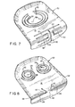
- the posterior supporting portion 102 includes a rear portion provided with a plurality of support members 130a-130d and a front portion having a plurality of flexible support members 132a, 132b provided by a patterned arrangement of a plurality of elongated openings 134.
- the elongated openings 134 include generally U-shaped openings symmetrically arranged about a pair of co-linear straight openings arranged along the rear and forward portions of the posterior supporting portion 102.
- the locations 136 on the support members 130a, 130b, as indicated in phantom, are so arranged to support the left and right ischial tuberosity of a person.
- the flexible support members 132a, 132b are adapted for supporting the upper leg portion of a person when normally seated.
- the flexible support member 132a, 132b additionally will support the posterior region of a person when slid forward in the chair 100, for example, left and right ischial tuberosity at locations 137, as indicated in phantom. This provides an ergonomic support even in the forward position when one sits on the front edge of the posterior supporting portion 102 of the chair 100.
- the posterior portion 102 may include support members 130a-130d and flexible support members 1 32a, 132b of different cross-sectional areas, or laminated with different materials having different flexibility and resiliency characteristics to achieve controlled flexibility and resiliency of the posterior supporting portion. Additionally, the supporting members 130a-130d and flexible supporting members 132a, 132b function as resilient cantilevers to achieve controlled support of the posterior portion of a person.
- the posterior supporting portion 102 may be secured to the supporting frame 106 by centrally disposed pivot points 138. As such, the posterior supporting portion 102 will function by twisting and flexing about pivot points 138 to provide continuous adjustment and conforming to the posterior region of a person. Where less flexibility is desired, the posterior supporting portion 102 may be secured to the supporting frame 106 at spaced-apart connecting points 140. Thus, it should be understood that the posterior supporting portion 102 is provided with a number of design elements which permit great latitude in flexibilty, resiliency and ability to adjust and conform to the posterior region of a person.
- the posterior supporting portion 102 is shaped to provide a posterior supporting surface 141 which is contoured, i.e., three-dimensional, by employing non-planar, compound curves.
- the supporting surface 141 comfortably conforms to the overall posterior region as one sits while the support members 130 and flexible support members 132 continuously adjust and conform to the posterior region of a person when in different sitting positions.
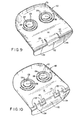
- the concentric support members 130 as shown in FIG. 7, are formed between concentric C-shaped elongated openings 134.
- FIG. 7 are formed between concentric C-shaped elongated openings 134.
- the support members 130 are formed between a pair of adjacent spiral-shaped elongated openings 134. It should therefore be understood that the posterior supporting portion 102 can be constructed to include a variety of shaped support members 130 as a result of providing a patterned elongated opening 134. As further shown in FIGS. 7 and 8, locations 136 for supporting the left and right ischial tuberosities are provided where the posterior supporting portion 102 has its greatest flexibility, i.e., on the central support member 130.
- each posterior supporting portion 102 is provided with a variety of patterned elongated openings 134 to provide flexible support member 132 of various shapes and sizes.
- the elongated openings 134 may be straight openings, U-shaped openings, T-shaped openings, V-shaped openings, L-shaped openings and the like, to provide the various patterns illustrated.
- the front portion of the posterior supporting portion 102 may be curved downwardly in a so-called waterfall effect, which portion includes the flexible support members 132.
- the center axis 142 of curvature for the front portion of the posterior supporting portion 102 extends through the base and leg of the U-shaped and L-shaped elongated openings 134.
- the support members 130 and flexible support members 132 can be constructed of different cross-sectional areas, or laminated with different materials having different flexibility and resiliency characteristics, or varying contoured supporting surfaces to achieve controlled flexibility and resiliency of the posterior supporting portion 102.
- the posterior supporting portion 102 in accordance with the preferred embodiment, is provided with a number of design elements which permit great latitude in flexibility, resiliency and ability to adjust and conform to the posterior region of a person.
- FIGS. 13 and 14 there is disclosed another embodiment of the present invention, wherein the chair 1 00 is provided with an upholstered outer covering 144 hiding from view the posterior supporting portion 102 and lumbar supporting portion 104.
- the posterior supporting portion 102 includes a separate upholstered front sitting position support 145 constructed to include flexible support members 132 (not shown) as described with reference to FIGS. 1 and 7-12.
- the lumbar supporting portion 104 of FIG. 13 is constructed of three rows of support members 110, while being constructed of four rows of support members in the embodiment shown in FIG. 14. Further, the posterior supporting portion 102 is constructed similar to the lumbar supporting portion 104.
- the support members 130 of the posterior supporting portion 102 are arranged in a serpentine or sinusoidal shape in multiple rows to individually and cooperatively provide flexible support for the posterior region of a person. It should therefore be understood that the principles of the present invention provide for a great variety in latitude and flexibility in the design and construction of the posterior supporting portion 102 and lumbar supporting portion 10 4 .
- the chair 100 is constructed of a blow molded shell 146 including a posterior supporting shell portion 148 and a lumbar supporting shell portion 150.
- the posterior and lumbar supporting shell portions 148, 150 include inner shell members 152, 154 and outer shell members 156, 158, respectively, defining a cavity 160 therebetween.
- the posterior and lumbar supporting shells 148, 150 are integrally joined by a central connecting shell portion 162.
- the support members 110 of the lumbar supporting shell portion 150 and the support members 130 and flexible support members 132 of the posterior supporting shell 148 are, respectively, formed in the inner shell members 15 4 , 152 by, for example, laser cutting, molding, hot-knife cutting and the like.
- the shell 146 may be manufactured from a variety of engineered plastics, for example, polycarbonates and the like.
- the support members 110 of the lumbar supporting shell portion 150 and the support members 130 and flexible support members 132 of the posterior supporting shell portion 148 may be constructed to include the various features thus far described with respect to the other embodiments of the present invention, as shown in FIGS. 1-14.
- the cavity 160 may be filled with foam blown therein, for example, polyurethane foam, to provide extra support and cushioning.
- the posterior and lumbar supporting shell portions 148, 150 may be upholstered or may be provided with self-skinning foam cushioning material to hide the support members 110, 130 and flexible support members 132.
- a tilt mechanism (not shown) for the chair 1 00 may be hidden within the cavity 160 of the posterior supporting shell 148 for attaching a pedestal base 163 thereto.
- the chair 100 as in the other embodiments, may be provided with arms (not shown), if desired.
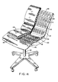
- FIG. 16 another embodiment of the chair 100 is shown, wherein the posterior supporting shell portion 148 and lumbar supporting shell portion 150 are separately formed and connected together by a J-shaped member 164.
- the J-shaped member 164 is secured to the outer shell members 156, 158 of the posterior and lumbar supporting shell portions 148, 150.
- the J-shaped member 164 permits flexing of the lumbar supporting shell portion 150 relative to the posterior supporting shell portion 148.
- the lumbar supporting shell portion 150 can be attached to the posterior supporting shell portion 148 by means of side frame members (not shown) in the manner described with reference to the embodiment illustrated in FIG. 1.
- FIG. 17 there is shown another embodiment of the present invention, wherein the posterior and lumbar supporting shell portions 148, 150 are joined together by a connecting shell portion 1 62 having an inner shell member 166 and an outer shell member 168.
- the inner and outer shell members 166, 168 are pinched together to have a reduced cross-sectional area, so as to be flexible, thereby functioning in the manner of the J-shaped member 164, as described with reference to FIG. 16.
- FIG. 18 there is disclosed a perspective view of an ergonomic chair 100 constructed in accordance with the preferred embodiment of the present invention.
- the chair 100 includes an ergonomic lumbar supporting portion 104 constructed in accordance with the lumbar supporting portion, as shown and described with reference to FIGS. 4-6.
- the chair 100 includes a posterior supporting portion 102 constructed generally in accordance with the posterior supporting portions, as shown and described in FIGS. 7-11 and specifically in FIG. 12.
- the posterior and lumbar supporting portions 102, 104 include contoured body supporting surfaces 126, 126', 141 formed from compound curves, i.e., non-planar curved surfaces, to provide an effective ergonomic support.
- the support members 110, 130 and flexible support members 132 individually and cooperatively provide flexible support for the lumbar and posterior regions of a person, which support members automatically conform to one's body for different sitting positions.
- the support members 110, 130 and flexible support members 132 can be constructed of different cross-sectional areas, or laminated with different materials having different flexibility and resiliency characteristics, or varying contoured supporting surfaces to achieve controlled flexibility and resiliency of the posterior and lumbar supporting portions 102, 104.
- the ergonomic chair 100 including the posterior and lumbar supporting portions 102, 104, is provided with a number of design elements which permit great latitude in flexibility, resiliency and ability to adjust and conform to the supported region of a person during different sitting positions without the need of mechanical elements.
- the posterior and lumbar supporting portions 102, 104 can be upholstered and cushioned in the same manner as described with reference to the chair illustrated in FIGS. 13 and 14.
- an ergonomic chair 100 which adjusts and conforms to body movement without mechanical components, which is inexpensive to manufacture from a variety of materials, which includes a posterior and lumbar supporting portion having non-planar, contoured supporting surfaces formed of compound curves, each of unitary construction, which employs patterned resilient cantilevers to achieve controlled support, which can be blow molded to provide an integral posterior and lumbar supporting portion, and whose flexibility and resiliency can be readily varied by design changes.
- the chair 100 specifically the posterior and lumbar supporting portions 102, 104 illustrated in FIG. 1 through FIG. 1 2 , can be upholstered and cushioned in the same manner as described with reference to the chair illustrated in FIGS. 13 and 14. It is therefore to be understood that numerous modifications may be made in the illustrative embodiments and that other arrangements may be devised without departing from the spirit and scope of the present invention, as defined by the appended claims.
Landscapes
- Chair Legs, Seat Parts, And Backrests (AREA)
- Air-Conditioning For Vehicles (AREA)
Applications Claiming Priority (2)
| Application Number | Priority Date | Filing Date | Title |
|---|---|---|---|
| US774900 | 1985-09-11 | ||
| US06/774,900 US4660887A (en) | 1985-09-11 | 1985-09-11 | Ergonomic support |
Publications (2)
| Publication Number | Publication Date |
|---|---|
| EP0216578A2 true EP0216578A2 (de) | 1987-04-01 |
| EP0216578A3 EP0216578A3 (de) | 1987-10-14 |
Family
ID=25102630
Family Applications (1)
| Application Number | Title | Priority Date | Filing Date |
|---|---|---|---|
| EP86307015A Ceased EP0216578A3 (de) | 1985-09-11 | 1986-09-11 | Ergonomische Körperstütze |
Country Status (6)
| Country | Link |
|---|---|
| US (1) | US4660887A (de) |
| EP (1) | EP0216578A3 (de) |
| JP (1) | JPS6266814A (de) |
| KR (1) | KR870002802A (de) |
| AU (1) | AU6232086A (de) |
| CA (1) | CA1256011A (de) |
Cited By (9)
| Publication number | Priority date | Publication date | Assignee | Title |
|---|---|---|---|---|
| US5664835A (en) * | 1994-03-25 | 1997-09-09 | Peter Roeder | Chair |
| DE19746304A1 (de) * | 1997-10-21 | 1999-04-22 | Thomas Brueckner | Elastischer Stuhl |
| JP2002199957A (ja) * | 2000-09-28 | 2002-07-16 | Formway Furniture Ltd | オフィス用リクライン椅子 |
| RU2199258C1 (ru) * | 2002-02-14 | 2003-02-27 | Быков Алексей Алексеевич | Устройство для сидения |
| WO2004074039A1 (de) * | 2003-02-24 | 2004-09-02 | Recaro Aircraft Seating Gmbh & Co. Kg | Sitz, insbesondere flugzeug-oder fahrzeugsitz |
| US6840582B2 (en) | 2002-05-14 | 2005-01-11 | Formway Furniture Limited | Height adjustable arm assembly |
| WO2006107214A1 (en) | 2005-04-08 | 2006-10-12 | Peter Opsvik As | Chair comprising a plate body attached to a base where a part of said plate body is designed as a torsion body. |
| WO2007112243A2 (en) | 2006-03-24 | 2007-10-04 | Humanscale Corporation | Ergonomic side chair |
| CN102512010A (zh) * | 2011-12-15 | 2012-06-27 | 尹旭 | 一种支撑腰椎坐垫 |
Families Citing this family (83)
| Publication number | Priority date | Publication date | Assignee | Title |
|---|---|---|---|---|
| US5567012A (en) * | 1986-04-10 | 1996-10-22 | Steelcase, Inc. | Chair control |
| IT1230689B (it) * | 1987-09-08 | 1991-10-29 | Cassina Spa | Metodo per realizzare mobili, particolarmente poltrone, divani o simili, da fogli di feltro trattati con sostanze indurenti e mobili relativi |
| US4781417A (en) * | 1987-12-07 | 1988-11-01 | Ford Motor Company | Upholstered seat cushion support |
| US4962964A (en) * | 1988-11-03 | 1990-10-16 | Warren Snodgrass | Flexible plastic seating shell |
| US4887865A (en) * | 1988-11-08 | 1989-12-19 | Daniel Dawidzon | Orthopedic seat and backrest combination |
| US5154485A (en) * | 1990-05-11 | 1992-10-13 | Fleishman Gregg R | Spring plate furniture |
| JPH0817730B2 (ja) * | 1991-05-21 | 1996-02-28 | 株式会社イトーキ | 背と座がシンクロ動作する椅子におけるシェル構造体 |
| US5328245A (en) * | 1992-10-30 | 1994-07-12 | Thomas J. Marks | Chair having adjustable back support |
| US5419617A (en) * | 1993-06-08 | 1995-05-30 | Hon Industries, Inc. | Detachable chair arm |
| US5415459A (en) * | 1993-06-08 | 1995-05-16 | Hon Industries, Inc. | Adjustable width arm rest |
| US5582460A (en) * | 1993-06-11 | 1996-12-10 | Hon Industries Inc. | Pivotable and height-adjustable chair back rest assembly and blow-molded back rest therefor |
| US5383677A (en) * | 1994-03-14 | 1995-01-24 | Thomas; Timothy N. | Bicycle body support apparatus |
| US6702391B1 (en) | 1995-06-07 | 2004-03-09 | Grant Stipek | Furniture with molded frame |
| US5577811A (en) * | 1995-06-07 | 1996-11-26 | Hon Industries Inc. | Ergonomic chair |
| FR2736309B1 (fr) * | 1995-07-05 | 1997-09-26 | Cesa | Siege pour vehicule automobile |
| USD407576S (en) | 1997-04-30 | 1999-04-06 | Haworth, Inc. | Chair |
| US5934758A (en) | 1997-04-30 | 1999-08-10 | Haworth, Inc. | Membrane chair |
| US5951110A (en) | 1997-10-17 | 1999-09-14 | Irwin Seating Company | Contoured plastic seat back |
| US6412869B1 (en) | 1999-05-27 | 2002-07-02 | Steelcase Development Corporation | Nestable synchrotilt chair |
| USD423261S (en) * | 1999-08-31 | 2000-04-25 | Haworth, Inc. | Chair |
| USD451693S1 (en) | 2000-05-25 | 2001-12-11 | Steelcase Development Corporation | Chair |
| USD456159S1 (en) | 2000-05-25 | 2002-04-30 | Steelcase Development Corporation | Chair |
| USD457739S1 (en) | 2000-05-25 | 2002-05-28 | Steelcase Development Corporation | Chair |
| US6409268B1 (en) | 2000-06-09 | 2002-06-25 | Stylex, Inc. | Flexible chair back |
| US6726285B2 (en) | 2000-07-03 | 2004-04-27 | Herman Miller, Inc. | Cellular chair construction |
| IT1318840B1 (it) * | 2000-09-08 | 2003-09-10 | Gianfranco Poli | Procedimento per realizzare sedute ed elementi di arredo, relativesedute ed elementi. |
| USD463144S1 (en) | 2000-09-28 | 2002-09-24 | Formway Furniture Limited | Chair |
| USD460300S1 (en) | 2000-09-28 | 2002-07-16 | Formway Furniture Limited | Slotted seat panel for a chair |
| AUPR054400A0 (en) | 2000-09-29 | 2000-10-26 | Formway Furniture Limited | A castor |
| GB0106247D0 (en) * | 2001-03-14 | 2001-05-02 | Williams David N L | Improvements relating to supports |
| GB0114581D0 (en) * | 2001-06-14 | 2001-08-08 | White Adam | Twister seat |
| US6811218B2 (en) | 2001-12-14 | 2004-11-02 | Kimball International, Inc. | Chair with conforming seat |
| US20030127896A1 (en) * | 2001-12-14 | 2003-07-10 | Deimen Michael L. | Chair with lumbar support and conforming back |
| DE102005020247B3 (de) * | 2005-04-28 | 2006-11-30 | Bock 1 Gmbh & Co. Kg | Sitzmöbel, insbesondere Bürostuhl |
| GB2433197B (en) * | 2005-12-15 | 2009-01-07 | R G E Engineering Company | Padded seat with resilient integral bending region |
| US7775600B2 (en) | 2006-04-28 | 2010-08-17 | Steelcase Development Corporation | Seating construction and method of assembly |
| USD564264S1 (en) | 2006-04-28 | 2008-03-18 | Steelcase Development Corporation | Seating unit |
| BRPI0621978B1 (pt) * | 2006-08-15 | 2020-02-04 | Humanscale Corp | aparelho para sentar com movimento de reclinar |
| US7857388B2 (en) * | 2007-06-01 | 2010-12-28 | Steelcase Inc. | Seating unit with adjustable lumbar device |
| US7806477B2 (en) * | 2008-02-29 | 2010-10-05 | La-Z-Boy Incorporated | Furniture member lumbar support system |
| CN102098945B (zh) | 2008-05-02 | 2013-11-06 | 霍沃思公司 | 用于重力响应式椅子的张力机构 |
| EP2252179B1 (de) | 2008-05-26 | 2012-07-11 | Steelcase Inc. | Nachgiebige rückseite für eine sitzeinheit |
| US7654617B2 (en) * | 2008-06-06 | 2010-02-02 | Mity-Lite, Inc. | Flexible chair seat |
| DE102008050550B3 (de) * | 2008-10-06 | 2010-09-16 | Fico Cables Lda | Stützmatte |
| US8317269B2 (en) | 2008-12-24 | 2012-11-27 | Mity-Lite, Inc. | Mesh stacking chair |
| US8033612B2 (en) | 2008-12-24 | 2011-10-11 | Mity-Lite, Inc. | Comfortable mesh folding chair |
| US8454093B2 (en) | 2008-12-24 | 2013-06-04 | Mity-Lite, Inc. | Mesh chair with open-end hoop |
| US8322787B2 (en) | 2008-12-24 | 2012-12-04 | Mity-Lite, Inc. | Clamping joint for a chair |
| DE102009006717A1 (de) * | 2009-01-29 | 2010-08-05 | Recaro Aircraft Seating Gmbh & Co. Kg | Passagiersitzvorrichtung |
| USD599127S1 (en) | 2009-04-13 | 2009-09-01 | Mity-Lite, Inc. | Mesh folding chair |
| ES2332766B1 (es) * | 2009-07-20 | 2010-10-01 | Actiu Berbegal Y Formas, S.A. | Asiento para sillas de oficina. |
| JP5467814B2 (ja) * | 2009-08-19 | 2014-04-09 | 株式会社イトーキ | 椅子の背もたれ又は座 |
| USD648554S1 (en) | 2009-11-04 | 2011-11-15 | Mity-Lite, Inc. | Mesh stacking chair |
| AU2011250953A1 (en) | 2010-05-10 | 2012-02-02 | Hip Innovations, Llc | Apparatuses and methods for increasing support provided by cushioned and other occupant supporting furniture |
| JP5593523B2 (ja) * | 2010-05-25 | 2014-09-24 | コクヨ株式会社 | 椅子 |
| JP5592171B2 (ja) * | 2010-06-16 | 2014-09-17 | 愛知株式会社 | 身体支持部材および椅子 |
| US8590978B2 (en) * | 2010-09-15 | 2013-11-26 | Ford Global Technologies, Llc | Ultra-thin seat carrier |
| USD660612S1 (en) | 2010-11-16 | 2012-05-29 | Mity-Lite, Inc. | Mesh banquet chair |
| US8678505B2 (en) * | 2010-12-21 | 2014-03-25 | Tachi-S Co., Ltd. | Seat cushion of vehicle seat |
| CN102529772B (zh) * | 2010-12-29 | 2015-01-14 | 株式会社塔捷斯 | 车辆用座椅的座椅座垫 |
| KR101155211B1 (ko) * | 2011-08-16 | 2012-06-13 | 윤욱 | 요추지지방석 |
| US8919880B2 (en) * | 2012-03-27 | 2014-12-30 | Haworth, Inc. | Flexible seating surface |
| US9609952B2 (en) * | 2012-05-04 | 2017-04-04 | Itoki Corporation | Chair, especially, office chair |
| US9661930B2 (en) | 2012-09-21 | 2017-05-30 | Steelcase Inc. | Chair construction |
| US9480339B2 (en) * | 2012-12-31 | 2016-11-01 | Sava Cvek | Seat with pelvic support |
| USD696545S1 (en) | 2013-07-30 | 2013-12-31 | Steelcase, Inc. | Rear surface of a chair back |
| US9789790B2 (en) * | 2014-10-03 | 2017-10-17 | Ford Global Technologies, Llc | Tuned flexible support member and flexible suspension features for comfort carriers |
| US9560917B2 (en) | 2014-11-26 | 2017-02-07 | Steelcase Inc. | Recline adjustment system for chair |
| US10194750B2 (en) | 2015-04-13 | 2019-02-05 | Steelcase Inc. | Seating arrangement |
| US10966527B2 (en) | 2017-06-09 | 2021-04-06 | Steelcase Inc. | Seating arrangement and method of construction |
| US10021984B2 (en) | 2015-04-13 | 2018-07-17 | Steelcase Inc. | Seating arrangement |
| US11259637B2 (en) | 2015-04-13 | 2022-03-01 | Steelcase Inc. | Seating arrangement |
| CN108601453B (zh) * | 2016-02-05 | 2021-11-05 | 佛姆维家具有限公司 | 椅子和部件 |
| US10463153B2 (en) * | 2016-06-09 | 2019-11-05 | Steelcase Inc. | Seating arrangement |
| US10279714B2 (en) | 2016-08-26 | 2019-05-07 | Ford Global Technologies, Llc | Seating assembly with climate control features |
| CN109788851B (zh) | 2016-09-29 | 2022-05-27 | 斯迪尔科斯公司 | 柔顺的座椅结构 |
| US10813463B2 (en) | 2017-12-05 | 2020-10-27 | Steelcase Inc. | Compliant backrest |
| US11291305B2 (en) | 2017-12-05 | 2022-04-05 | Steelcase Inc. | Compliant backrest |
| JP7212918B2 (ja) * | 2018-08-24 | 2023-01-26 | 株式会社タイカ | 着座用クッション及び椅子用座面 |
| US11589678B2 (en) | 2019-01-17 | 2023-02-28 | Hni Technologies Inc. | Chairs including flexible frames |
| US11147379B2 (en) | 2019-08-22 | 2021-10-19 | Mity-Lite, Inc. | Cushion for folding chair |
| WO2021055441A1 (en) | 2019-09-18 | 2021-03-25 | Steelcase Inc. | Body support member with lattice structure |
| US11690457B2 (en) * | 2020-02-04 | 2023-07-04 | Hni Technologies Inc. | Chair with flexible internal support |
Family Cites Families (10)
| Publication number | Priority date | Publication date | Assignee | Title |
|---|---|---|---|---|
| US2649146A (en) * | 1947-11-28 | 1953-08-18 | Roy S Sanford | Barrel chair |
| US3165356A (en) * | 1963-12-17 | 1965-01-12 | Douglas J Geier | Shock absorbing support and restraint means |
| US4108490A (en) * | 1977-07-05 | 1978-08-22 | Marin Jose Antonio T | Foldable chair |
| US4390204A (en) * | 1978-01-04 | 1983-06-28 | Gregg Fleishman | Portable furniture |
| US4202581A (en) * | 1978-01-04 | 1980-05-13 | Gregg Fleishman | Support means for portable furniture |
| JPS5588713A (en) * | 1978-12-27 | 1980-07-04 | Tachikawa Spring Co | Sheet for car in synthetic resin |
| EP0032839B1 (de) * | 1980-01-21 | 1984-05-16 | Bernard Curtis Watkin | Sitzschalen |
| US4390209A (en) * | 1980-01-25 | 1983-06-28 | Toyo Kogyo Co., Ltd. | Plastic seat-back framework and method for the manufacture thereof |
| US4502731A (en) * | 1981-06-01 | 1985-03-05 | Snider Robert A | Seat frame |
| US4572578A (en) * | 1984-08-08 | 1986-02-25 | Perkins Patricia A | Back rest |
-
1985
- 1985-09-11 US US06/774,900 patent/US4660887A/en not_active Expired - Lifetime
-
1986
- 1986-09-03 AU AU62320/86A patent/AU6232086A/en not_active Abandoned
- 1986-09-03 CA CA000517413A patent/CA1256011A/en not_active Expired
- 1986-09-08 JP JP61212514A patent/JPS6266814A/ja active Pending
- 1986-09-11 KR KR1019860007633A patent/KR870002802A/ko not_active Ceased
- 1986-09-11 EP EP86307015A patent/EP0216578A3/de not_active Ceased
Cited By (20)
| Publication number | Priority date | Publication date | Assignee | Title |
|---|---|---|---|---|
| US5664835A (en) * | 1994-03-25 | 1997-09-09 | Peter Roeder | Chair |
| DE19746304A1 (de) * | 1997-10-21 | 1999-04-22 | Thomas Brueckner | Elastischer Stuhl |
| US6910741B2 (en) | 2000-09-28 | 2005-06-28 | Formway Furniture Limited | Lumbar support |
| US7798573B2 (en) | 2000-09-28 | 2010-09-21 | Formway Furniture Limited | Reclinable chair |
| US6802566B2 (en) | 2000-09-28 | 2004-10-12 | Formway Furniture Limited | Arm assembly for a chair |
| US6817667B2 (en) | 2000-09-28 | 2004-11-16 | Formway Furniture Limited | Reclinable chair |
| US6874852B2 (en) | 2000-09-28 | 2005-04-05 | Formway Furniture Limited | Lumbar support |
| US6908159B2 (en) | 2000-09-28 | 2005-06-21 | Formway Furniture Limited | Seat for a reclining office chair |
| JP2002199957A (ja) * | 2000-09-28 | 2002-07-16 | Formway Furniture Ltd | オフィス用リクライン椅子 |
| US7441839B2 (en) | 2000-09-28 | 2008-10-28 | Formway Furniture Limited | Reclinable chair |
| RU2199258C1 (ru) * | 2002-02-14 | 2003-02-27 | Быков Алексей Алексеевич | Устройство для сидения |
| US6840582B2 (en) | 2002-05-14 | 2005-01-11 | Formway Furniture Limited | Height adjustable arm assembly |
| WO2004074039A1 (de) * | 2003-02-24 | 2004-09-02 | Recaro Aircraft Seating Gmbh & Co. Kg | Sitz, insbesondere flugzeug-oder fahrzeugsitz |
| US7806476B2 (en) | 2003-02-24 | 2010-10-05 | Recaro Aircraft Seating Gmbh & Co. Kg | Seat, especially an airplane or vehicle seat |
| WO2006107214A1 (en) | 2005-04-08 | 2006-10-12 | Peter Opsvik As | Chair comprising a plate body attached to a base where a part of said plate body is designed as a torsion body. |
| EP2039268A1 (de) * | 2006-03-24 | 2009-03-25 | Humanscale Corporation | Ergonomischer Seitenstuhl |
| EP2001336A4 (de) * | 2006-03-24 | 2009-03-25 | Humanscale Corp | Ergonomischer seitenstuhl |
| WO2007112243A2 (en) | 2006-03-24 | 2007-10-04 | Humanscale Corporation | Ergonomic side chair |
| US7971935B2 (en) | 2006-03-24 | 2011-07-05 | Humanscale Corporation | Ergonomic side chair |
| CN102512010A (zh) * | 2011-12-15 | 2012-06-27 | 尹旭 | 一种支撑腰椎坐垫 |
Also Published As
| Publication number | Publication date |
|---|---|
| AU6232086A (en) | 1987-03-12 |
| JPS6266814A (ja) | 1987-03-26 |
| EP0216578A3 (de) | 1987-10-14 |
| CA1256011A (en) | 1989-06-20 |
| US4660887A (en) | 1987-04-28 |
| KR870002802A (ko) | 1987-04-13 |
Similar Documents
| Publication | Publication Date | Title |
|---|---|---|
| US4660887A (en) | Ergonomic support | |
| US5411316A (en) | Single piece chair shell | |
| US7455365B2 (en) | Seating structure having flexible support surface | |
| US4892356A (en) | Chair shell | |
| EP1401306B1 (de) | Sitze | |
| US5314240A (en) | Shell structure for use with a chair having synchronously moving seat and seat back | |
| US4032190A (en) | Ergonomically designed chair | |
| CN1822781B (zh) | 用于座位的舒适表面 | |
| US5024485A (en) | Front and back adjustable rocking seat support arrangement for seat having relatively adjustable sections | |
| US9504326B1 (en) | Reclining chair | |
| US11864658B2 (en) | Chair and components | |
| US6722735B2 (en) | Chair with synchronously moving seat and seat back | |
| EP1192879B1 (de) | Sitz für einen neigbaren Bürostuhl | |
| US5288127A (en) | Rocking seat | |
| US7226127B1 (en) | Ergonomic chair backrest | |
| US20040140701A1 (en) | Backrest for a seating structure with an adjustable sacral support | |
| US6517156B1 (en) | Backrest structure for a leisure chair | |
| US5366273A (en) | Chair or the like | |
| US7147288B2 (en) | Backrest | |
| KR960030853A (ko) | 등받이가 분리되는 의자 | |
| JP4183084B2 (ja) | 椅子及びその背もたれ | |
| US4046422A (en) | Chair | |
| JP2741269B2 (ja) | 使用者に合わせて変化する椅子 | |
| KR102574701B1 (ko) | 자세 교정형 의자 | |
| KR200395763Y1 (ko) | 등받이 분할형 의자 |
Legal Events
| Date | Code | Title | Description |
|---|---|---|---|
| PUAI | Public reference made under article 153(3) epc to a published international application that has entered the european phase |
Free format text: ORIGINAL CODE: 0009012 |
|
| AK | Designated contracting states |
Kind code of ref document: A2 Designated state(s): AT BE CH DE FR GB IT LI LU NL SE |
|
| PUAL | Search report despatched |
Free format text: ORIGINAL CODE: 0009013 |
|
| AK | Designated contracting states |
Kind code of ref document: A3 Designated state(s): AT BE CH DE FR GB IT LI LU NL SE |
|
| 17P | Request for examination filed |
Effective date: 19880412 |
|
| 17Q | First examination report despatched |
Effective date: 19890524 |
|
| STAA | Information on the status of an ep patent application or granted ep patent |
Free format text: STATUS: THE APPLICATION HAS BEEN REFUSED |
|
| 18R | Application refused |
Effective date: 19910503 |
|
| RIN1 | Information on inventor provided before grant (corrected) |
Inventor name: NEAGLE, RICHARD MARTIN Inventor name: FLEMING, PHILIP SOMERS |