EP0216609B1 - Sammlungs- und Deutungsverfahren von seismischen Daten zur Erwerbung lithologischer Parameter - Google Patents
Sammlungs- und Deutungsverfahren von seismischen Daten zur Erwerbung lithologischer Parameter Download PDFInfo
- Publication number
- EP0216609B1 EP0216609B1 EP86307215A EP86307215A EP0216609B1 EP 0216609 B1 EP0216609 B1 EP 0216609B1 EP 86307215 A EP86307215 A EP 86307215A EP 86307215 A EP86307215 A EP 86307215A EP 0216609 B1 EP0216609 B1 EP 0216609B1
- Authority
- EP
- European Patent Office
- Prior art keywords
- seismic
- lithological
- strata
- source
- offset
- Prior art date
- Legal status (The legal status is an assumption and is not a legal conclusion. Google has not performed a legal analysis and makes no representation as to the accuracy of the status listed.)
- Expired - Lifetime
Links
- 238000000034 method Methods 0.000 title claims description 53
- 230000006870 function Effects 0.000 claims description 17
- 239000000203 mixture Substances 0.000 claims description 11
- 238000012937 correction Methods 0.000 claims description 9
- 239000000463 material Substances 0.000 claims description 9
- 238000007620 mathematical function Methods 0.000 claims description 7
- 239000007788 liquid Substances 0.000 claims description 3
- 230000000007 visual effect Effects 0.000 claims description 2
- 239000010410 layer Substances 0.000 description 82
- 239000004576 sand Substances 0.000 description 34
- 229930195733 hydrocarbon Natural products 0.000 description 27
- 150000002430 hydrocarbons Chemical class 0.000 description 27
- 239000007789 gas Substances 0.000 description 23
- 239000004215 Carbon black (E152) Substances 0.000 description 17
- 230000001965 increasing effect Effects 0.000 description 11
- 238000007906 compression Methods 0.000 description 7
- 230000006835 compression Effects 0.000 description 7
- 238000002310 reflectometry Methods 0.000 description 6
- 238000010586 diagram Methods 0.000 description 5
- 230000005284 excitation Effects 0.000 description 5
- 238000009825 accumulation Methods 0.000 description 4
- 230000035508 accumulation Effects 0.000 description 4
- 239000011148 porous material Substances 0.000 description 4
- 244000166071 Shorea robusta Species 0.000 description 3
- 235000015076 Shorea robusta Nutrition 0.000 description 3
- 238000013459 approach Methods 0.000 description 3
- 230000007423 decrease Effects 0.000 description 3
- 230000008021 deposition Effects 0.000 description 3
- 238000000151 deposition Methods 0.000 description 3
- 230000000694 effects Effects 0.000 description 3
- 238000012545 processing Methods 0.000 description 3
- XLYOFNOQVPJJNP-UHFFFAOYSA-N water Substances O XLYOFNOQVPJJNP-UHFFFAOYSA-N 0.000 description 3
- 235000019738 Limestone Nutrition 0.000 description 2
- 230000014509 gene expression Effects 0.000 description 2
- 239000006028 limestone Substances 0.000 description 2
- 239000011159 matrix material Substances 0.000 description 2
- 230000015654 memory Effects 0.000 description 2
- VNWKTOKETHGBQD-UHFFFAOYSA-N methane Chemical compound C VNWKTOKETHGBQD-UHFFFAOYSA-N 0.000 description 2
- 238000001615 p wave Methods 0.000 description 2
- 230000004044 response Effects 0.000 description 2
- 239000011435 rock Substances 0.000 description 2
- 230000003068 static effect Effects 0.000 description 2
- GNFTZDOKVXKIBK-UHFFFAOYSA-N 3-(2-methoxyethoxy)benzohydrazide Chemical compound COCCOC1=CC=CC(C(=O)NN)=C1 GNFTZDOKVXKIBK-UHFFFAOYSA-N 0.000 description 1
- 238000012935 Averaging Methods 0.000 description 1
- FGUUSXIOTUKUDN-IBGZPJMESA-N C1(=CC=CC=C1)N1C2=C(NC([C@H](C1)NC=1OC(=NN=1)C1=CC=CC=C1)=O)C=CC=C2 Chemical compound C1(=CC=CC=C1)N1C2=C(NC([C@H](C1)NC=1OC(=NN=1)C1=CC=CC=C1)=O)C=CC=C2 FGUUSXIOTUKUDN-IBGZPJMESA-N 0.000 description 1
- 241000276498 Pollachius virens Species 0.000 description 1
- 101100464782 Saccharomyces cerevisiae (strain ATCC 204508 / S288c) CMP2 gene Proteins 0.000 description 1
- 230000015572 biosynthetic process Effects 0.000 description 1
- 239000003086 colorant Substances 0.000 description 1
- 238000004590 computer program Methods 0.000 description 1
- 238000007596 consolidation process Methods 0.000 description 1
- 238000013480 data collection Methods 0.000 description 1
- 230000001934 delay Effects 0.000 description 1
- 230000001419 dependent effect Effects 0.000 description 1
- 238000001514 detection method Methods 0.000 description 1
- 238000011161 development Methods 0.000 description 1
- 230000018109 developmental process Effects 0.000 description 1
- 238000005553 drilling Methods 0.000 description 1
- 239000002360 explosive Substances 0.000 description 1
- 238000001914 filtration Methods 0.000 description 1
- 239000012530 fluid Substances 0.000 description 1
- 238000005755 formation reaction Methods 0.000 description 1
- 238000009472 formulation Methods 0.000 description 1
- 238000010438 heat treatment Methods 0.000 description 1
- 230000001939 inductive effect Effects 0.000 description 1
- 238000011835 investigation Methods 0.000 description 1
- 230000001788 irregular Effects 0.000 description 1
- 238000005259 measurement Methods 0.000 description 1
- 239000003345 natural gas Substances 0.000 description 1
- 230000000750 progressive effect Effects 0.000 description 1
- 230000000717 retained effect Effects 0.000 description 1
- 238000007789 sealing Methods 0.000 description 1
- 238000000926 separation method Methods 0.000 description 1
- 239000002344 surface layer Substances 0.000 description 1
- 238000012360 testing method Methods 0.000 description 1
Images







Classifications
-
- G—PHYSICS
- G01—MEASURING; TESTING
- G01V—GEOPHYSICS; GRAVITATIONAL MEASUREMENTS; DETECTING MASSES OR OBJECTS; TAGS
- G01V1/00—Seismology; Seismic or acoustic prospecting or detecting
- G01V1/003—Seismic data acquisition in general, e.g. survey design
-
- G—PHYSICS
- G01—MEASURING; TESTING
- G01V—GEOPHYSICS; GRAVITATIONAL MEASUREMENTS; DETECTING MASSES OR OBJECTS; TAGS
- G01V1/00—Seismology; Seismic or acoustic prospecting or detecting
- G01V1/28—Processing seismic data, e.g. for interpretation or for event detection
- G01V1/282—Application of seismic models, synthetic seismograms
Definitions
- seismology The study of seismic disturbances in the earth, called seismology, has been used for decades in exploring for structural and stratigraphic traps. Exploration by seismology begins by artificially inducing a seismic surface disturbances using explosives, air guns or mechanical vibrators. The resulting seismic waves propagate into the earth and are partially reflected back toward the surface by the interfaces between geological layers. The reflected waves are then sensed and recorded by detectors on the surface at some measured distance from the seismic wave source. The portion of the wave that is reflected is determined by the reflection coefficient of each geological interface, which varies with the differences in the lithological characteristics between the upper and lower layers adjacent to the interface. See generally M.B. Dobrin. Introduction to Geophysical Prospecting (1976).
- the seismic waves reflected from various points in a vertical plane through the earth can be displayed side by side as traces on paper to obtain a "seismic section".
- Early seismologists directly recorded these traces in the field as side by side irregular lines, the length of which was proportional to the depth of the reflecting interfaces.
- Modern techniques record the reflected waves digitally on magnetic tape or in computer memories.
- the digitally recorded waves are later statically and dynamically corrected, usually by automated means, and are then displayed side by side for interpretation by a seismologist.
- Seismic Stratigraphy Hydrocarbon reservoirs are commonly found in stratigraphic traps of porous sand or sandstone. It is well known in the art that a deposition of sand is more probable in some environments than in others. For example, beach environments are likely to receive sand depositions. It has been found that some of the environments conducive to sand deposition where hydrocarbon reservoirs may later accumulate are associated with characteristic stratigraphic shapes. Because these sands usually have lithological parameters different from those of adjacent geological layers, the interface between the sand and the adjacent layers will reflect seismic waves. The art of recognizing the characteristic shapes of these sand environments on seismic sections is called "seismic stratigraphy".
- Figure 6 shows dramatic offset-amplitude variations in porous and nonporous water sand layers between two shale layers. These variations could incorrectly be interpreted as hydrocarbon indicators under methods of the prior art. However, knowledge of the lithological parameters would disprove the existence of hydrocarbons; both the porous and non-porous layers have Poisson's ratios that are too high for a gas reservoir.
- the present invention is intended to avoid the necessity for estimating the angles of incidence. Instead, it seeks to provide a practical means which may be fully automated to use seimic data for determining subsurface lithological parameters which may include Poisson's ratio, seismic wave velocity and material density. For these parameters, the actual composition of the geological strata concerned can be predicted.
- a method of investigating lithology or liquid or gas content of strata comprising the steps of:
- said method further comprises the step of:
- the invention enables the explorationist to use knowledge of the lithology of any geological layer to determine the lithology of an adjacent layer, which in turn may be used to determine the lithology of the next adjacent layer, and so on.
- the lithological parameters so determined for unknown layers may the be matched with the known lithological parameters of various types of known geological layers to determine accurately the actual composition of the layer in question.
- side by side traces are displayed that are functions of the reflected seismic wave amplitude corrected for seismic wave angle of incidence variations.
- the seismologist interprets these corrected traces.
- Poor signal-to-noise ratio data from two or more adjacent common midpoint gathers can be used together for determining the lithological parameters and corrected offset amplitude variations.
- the combined use of two or more common midpoint gathers in this manner may improve the signal-to-noise ratio of data.
- the procedures currently applied are limited by the fact that the offset dependent variable in the theoretical formulations is the angle of incidence, which changes at each interface and is therefore very difficult to determine after several interfaces.
- Practitioners attempt to overcome this limitation by introducing error-prone simplifying assumptions regarding the angle of incidence or by relying on trial and error forward modeling of the offset-amplitude relationships based on either the Zoeppritz equations or Bortfeld's approximation.
- forward modeling the model parameters are iterated until a fit with observed data is obtained. Because the angle of incidence changes at each interface, successive iterations require successive trial and error passes of ray tracing to relate the angle of incidence to the measured offset.
- This invention is intended to eliminate the necessity for estimating the angle of incidence through simplifying assumptions or forward modeling.
- Equation (6) may be inverted to express p as a function of x so that After substituting Equation (6) into Equation (5) and equating like powers to x to evaluate the coefficients, Equation (6) becomes Substituting Equation (7) into Equation (3) and retaining terms through x 4 , we have an expression for the reflection coefficient as a function of x.
- Equation (7) is useful for forward models of offset amplitude variation, it can be cast in a more useful form for estimating differences in lithological parameters by introducing the approximations so that: Equations 8 can be solved to yield expressions relating Poisson's ratio, velocity and density of a given layer to Poisson's ratio, velocity and density of the overlying layer, as follows
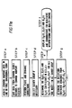
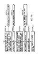
- Figure II shows a flow chart of the subprocesses together establish a total process under this embodiment.
- the discussion that follows will explain the elements of Figure II in terms of the definitions, background and theoretical developments given above.
- a fully programmed computer system such as that depicted in Figure 12 may be used.
- estimates of some lithological parameters, especially velocity and density, in one layer beneath a common midpoint may be helpful. Such estimates permit the process to determine the lithological parameters of an adjacent layer without beginning at the top layer, and also serve as a check on the process of determining the lithological parameters from the power series or orthogonal polynomial functions.
- the approximations can be obtained from well control data collected by methods known in the industry, such as by placing a seismic source and detector in a well to determine the seismic velocity over a short distance in the layer of placement. Approximations may also be obtained by using as a starting point the apparent average velocities of a seismic wave through the interfaces in question. Published velocity versus density relationships enable the seismologist to use these velocity approximations to obtain density approximations.
- the source will then be re-excited and the seismic signals generated will be recorded in the repositioned or simulated repositioned array, with a new corresponding midpoint associated with each trace.
- Midpoints from the second (and subsequent relocated excitations) will lie in the same physical location as midpoints from prior excitations but will be associated with a different offset.
- the stacking diagram in Figure 12 shows the relationship among the sources, detectors and common midpoints for a line acquisition procedure.
- the succession of common midpoints are each associated with traces from a progression of offsets. All the detector points that align vertically have the same common ground location. All the points which align diagonally up to the left represent traces with the same offset. The points which align horizontally represent traces recorded from a common source excitation. All detector points that align diagonally up to the right represent detectors recording reflections from the same common midpoint.
- the data that comes from the field will be grouped according to common source. Each group of traces corresponding to a common source excitation referred to as a field record.
- the common midpoint technique and stacking diagrams are known in the industry and are further described in U.S. Patent Number 4,316,268. Ostrander, for Method for Interpretation of Seismic Records to Yield Indication of Gaseous Hydrocarbons, the contents of which pertaining to common midpoint data collection are hereby incorporated by reference.
- the next step, illustrated in b of Figure II, is the sorting procedure wherein traces from the whole set of field records are sorted into groups with common midpoints, called common midpoint gathers.
- the common midpoint gathers are represented by the lines diagonally up to the right in Figure 12. Each trace is also identified with respect to detector location, source location and source-detector offset.
- Step d of Figure II represents further grouping of two or more adjacent corrected common midpoint gathers into gather groups in order to improve signal-to-noise ratios by averaging out noise.
- the dashed parallelogram in the stacking diagram of Figure 12 illustrates the data included in a gather group encompassing three common midpoint gathers, made up of a gather and the two gathers adjacent on each side.
- the number of common midpoint gathers in a gather group may be only one in good signal to noise ratio areas (and therefore this step would be omitted) and may be increased as the data quality decreases.
- a gather group with four common midpoint gathers will theoretically yield a signal-to noise ratio better than a gather group with just one common midpoint gather, although some precision may be sacrificed because the gather groups blend data from adjacent locations.
- Computer programs to accomplish gather groupings are standard features of many data processing packages available in the industry.
- the reflection coefficients for each gather group are expressed as mathematical functions of the offsets for successive time indexes (which corresponds to successive depths) in each gather group.
- the most direct procedure is to use the method of least squares with the data at each time index in accordance with Equation (7a) to define the set ao(t), a2(t) and a4(t) that best fits the sorted and corrected data.
- An alternate procedure is to fit the data set with a series of orthonormal polynomials, expressing reflection coefficients as functions of offset.
- step c in Figure II omit any correction for moveout.
- the resulting corrected data in each common midpoint gather will represent the reflectivity of the geological layer succession beneath such midpoint at the sequence of offsets sampled, unadjusted for the moveout time lag.
- the mathematical fitting of step e is done along a moveout trajectory to associate the coefficient set, or the actual reflection coefficients obtained as described below, with successive moveout or offset values.
- step f of Figure II selected coefficients or combinations of coefficients for a common midpoint may be plotted as a trace adjacent to such trace from the prior common midpoint, and so on to form a parameter trace seismic section. Digital plotters commonly used in the industry are helpful for performing this step.
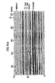
- Figure 14 illustrates a portion of a normal stacked (zero offset) seismic section and an ao(t) parameter section derived from the same seismic data.
- a stratum 30 shows an unresolved channel sand in the conventional normal stacked section of Figure 14a.
- the same stratum 34 is shown in Figure 14b with much better resolution and interpretive value to those skilled in the art.
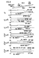
- coefficient trace sections such as a2(t), a 4 (t), a 2 (t)/ao(t) and a 4 (t)/a 2 (t) may also prove valuable in identifying geological layers as practitioners develop interpretive abilities. Trace sections for several coefficients are shown in Figure 8.
- the next step is to derive the effective reflection coefficient "spikes" ro(t), r 2 (t) and r 4. (t) for the layer series from the ao(t), a2(t) and a 4 (t) traces respectively using algorithms designed specifically for that purpose.
- a trace section of reflecting coefficients should show spikes at each reflecting interface, corresponding to a reflection at that interface.
- the trace section should show zero values between reflecting interfaces, corresponding to zero reflection between the reflecting interfaces.
- the statically and dynamically corrected reflection coefficient trace section appears to show reflections between the interfaces. These apparent reflections are because the seismic wave is not an impulse when it reflected from an interface or when it is detected by the detector.
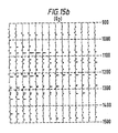
- Figures 16, 17 and 18 illustrate the velocity, density and Poisson's ratio profile estimates, respectively, derived from the data of Figure 15.
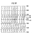
- Several important strata 36, 38 and 40 on Figures 16-18 will be apparent to those skilled in interpresting seismic sections.
- Statum 36 is the top of a sand layer called “D" sand.
- Statum 38 is the top of another sand layer called “J” sand.
- Statum 40 is the top of another sand layer called "Dakota" sand.
- the final steps require data relating the velocity, density and Poisson's ratio of each layer, determined as described above, to the lithology and pore content of such layers.
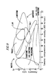
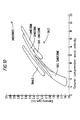
- a number of publications show these relationships for a wide range of lithological types, typically in the form of charts like those shown in Figures 9 and 10. Using those relationships a lithologic section, illustrated in Figure 19, can be generated.
- the Figure 19 section was generated by assigning trace magnitudes to various areas on a chart of seismic wave velocity and Poisson's ratio (such as the chart shown in Figure 9). The same result could be achieved by assigning different colours rather than different magnitudes to the areas.
- Figure 19 distinctly shoes the same strata 36, 38 and 40 as shown in the velocity, density and Poisson's ratio sections of Figures 16-18.
- the method described above provides the explorationist with a powerful tool for delineating hydrocarbon reservoirs and ascertaining hydrocarbon reservoir pore content.
Landscapes
- Engineering & Computer Science (AREA)
- Remote Sensing (AREA)
- Physics & Mathematics (AREA)
- Life Sciences & Earth Sciences (AREA)
- Acoustics & Sound (AREA)
- Environmental & Geological Engineering (AREA)
- Geology (AREA)
- General Life Sciences & Earth Sciences (AREA)
- General Physics & Mathematics (AREA)
- Geophysics (AREA)
- Geophysics And Detection Of Objects (AREA)
Claims (6)
Applications Claiming Priority (2)
| Application Number | Priority Date | Filing Date | Title |
|---|---|---|---|
| US77793985A | 1985-09-19 | 1985-09-19 | |
| US777939 | 1996-12-23 |
Publications (3)
| Publication Number | Publication Date |
|---|---|
| EP0216609A2 EP0216609A2 (de) | 1987-04-01 |
| EP0216609A3 EP0216609A3 (en) | 1988-09-21 |
| EP0216609B1 true EP0216609B1 (de) | 1991-08-28 |
Family
ID=25111771
Family Applications (1)
| Application Number | Title | Priority Date | Filing Date |
|---|---|---|---|
| EP86307215A Expired - Lifetime EP0216609B1 (de) | 1985-09-19 | 1986-09-19 | Sammlungs- und Deutungsverfahren von seismischen Daten zur Erwerbung lithologischer Parameter |
Country Status (6)
| Country | Link |
|---|---|
| US (1) | US4967401A (de) |
| EP (1) | EP0216609B1 (de) |
| AU (1) | AU592369B2 (de) |
| CA (1) | CA1280200C (de) |
| DE (1) | DE3681106D1 (de) |
| NO (1) | NO863745L (de) |
Cited By (1)
| Publication number | Priority date | Publication date | Assignee | Title |
|---|---|---|---|---|
| RU2309434C1 (ru) * | 2006-06-19 | 2007-10-27 | Югорский научно-исследовательский институт информационных технологий | Способ контроля разработки залежей углеводородов по микросейсмической эмиссии |
Families Citing this family (27)
| Publication number | Priority date | Publication date | Assignee | Title |
|---|---|---|---|---|
| US5257242A (en) * | 1991-07-24 | 1993-10-26 | Amoco Corporation | Method of geophysical exploration |
| US5487001A (en) * | 1993-05-28 | 1996-01-23 | Neff; Dennis B. | Method for determining petrophysical properties of a subterranean layer |
| US5578757A (en) * | 1994-08-09 | 1996-11-26 | The United States Of America As Represented By The Administrator Of The National Aeronautics And Space Administration | Method of Poisson's ratio imaging within a material part |
| US5583825A (en) * | 1994-09-02 | 1996-12-10 | Exxon Production Research Company | Method for deriving reservoir lithology and fluid content from pre-stack inversion of seismic data |
| US5706194A (en) * | 1995-06-01 | 1998-01-06 | Phillips Petroleum Company | Non-unique seismic lithologic inversion for subterranean modeling |
| FR2759781B1 (fr) * | 1997-02-14 | 1999-04-23 | France Telecom | Procede de controle des caracteristiques d'un sol par voie sismique et dispositif pour la mise en oeuvre de ce procede |
| GB9703529D0 (en) * | 1997-02-20 | 1997-04-09 | Geco As | A method of processing seismic data signals |
| RU2161809C2 (ru) * | 1998-11-30 | 2001-01-10 | Арутюнов Сергей Львович | Способ поиска углеводородов (варианты), контроля эксплуатации углеводородной залежи |
| US6694261B1 (en) * | 1999-06-07 | 2004-02-17 | Conoco Inc. | Method for identification of shallow water flow hazards using marine seismic data |
| RU2159944C1 (ru) * | 1999-08-26 | 2000-11-27 | Открытое Акционерное общество "Татнефть" Татарский научно-исследовательский и проектный институт нефти | Способ поиска и разведки многопластовых залежей нефти |
| RU2174693C2 (ru) * | 1999-12-24 | 2001-10-10 | Арутюнов Сергей Львович | Способ оценки глубины залегания нефтегазового месторождения |
| US7146329B2 (en) * | 2000-01-13 | 2006-12-05 | Erinmedia, Llc | Privacy compliant multiple dataset correlation and content delivery system and methods |
| US7139723B2 (en) * | 2000-01-13 | 2006-11-21 | Erinmedia, Llc | Privacy compliant multiple dataset correlation system |
| RU2169381C1 (ru) * | 2000-02-01 | 2001-06-20 | Закрытое акционерное общество Научно-производственная компания "Форум" | Способ сейсморазведки для прямого поиска и изучения нефтегазовых месторождений по данным преобразования, обработки и анализа упругих волновых полей в частотной области |
| FR2808336B1 (fr) * | 2000-04-26 | 2002-06-07 | Elf Exploration Prod | Methode d'interpretation chrono-stratigraphique d'une section ou d'un bloc sismique |
| RU2180128C1 (ru) * | 2001-06-04 | 2002-02-27 | Волож Юрий Абрамович | Способ построения сейсмостратиграфической модели разреза среды |
| RU2184986C1 (ru) * | 2001-06-13 | 2002-07-10 | Кобяков Николай Иванович | Способ локального прогнозирования нефтегазоносности ловушек на территориях, удаленных от области генерации углеводородов |
| US6826484B2 (en) * | 2001-07-31 | 2004-11-30 | Pgs Americas, Inc. | 3D prestack time migration method |
| US8000168B2 (en) * | 2006-12-08 | 2011-08-16 | Conocophillips Company | Dynamic source parameter selection for seismic vibrator data acquisition |
| CN101446645B (zh) * | 2007-11-27 | 2011-08-03 | 中国石油天然气股份有限公司 | 一种利用地震流体阻抗进行流体确定的方法 |
| CN103792575B (zh) * | 2012-11-01 | 2017-02-08 | 中国石油天然气集团公司 | 一种去骨架影响的致密砂岩气层识别评价方法 |
| WO2014159479A1 (en) * | 2013-03-14 | 2014-10-02 | Schlumberger Canada Limited | Direct fluid indicators in multiple segment prospects |
| CN105629327B (zh) * | 2015-12-31 | 2018-03-27 | 中国石油大学(华东) | 一种针对弱胶结、深层致密砂岩储层成岩相定量表征方法 |
| CN106547034B (zh) * | 2016-11-09 | 2018-11-02 | 西南石油大学 | 一种确定致密储层岩石脆性指数的方法 |
| CN112464719B (zh) * | 2020-10-26 | 2025-02-07 | 中国石油天然气集团有限公司 | 波阻抗曲线的归一化方法、装置、计算机设备及存储介质 |
| US20220413176A1 (en) * | 2021-06-28 | 2022-12-29 | Halliburton Energy Services, Inc. | Annulus Velocity Independent Time Domain Structure Imaging In Cased Holes Using Multi-Offset Secondary Flexural Wave Data |
| CN114488305B (zh) * | 2022-02-16 | 2022-09-30 | 重庆科技学院 | 一种无井新探区地震资料地质层位精细标定方法 |
Family Cites Families (14)
| Publication number | Priority date | Publication date | Assignee | Title |
|---|---|---|---|---|
| US4210968A (en) * | 1975-12-16 | 1980-07-01 | Lindseth Roy O | Seismic exploration technique |
| FR2346729A2 (fr) * | 1976-03-30 | 1977-10-28 | Elf Aquitaine | Methode d'exploration d'un milieu |
| CA1240026A (en) * | 1977-01-03 | 1988-08-02 | Chevron Research And Technology Company | Method for interpretation of seismic records to yield indications of gaseous hydrocarbons |
| US4316267A (en) * | 1977-01-03 | 1982-02-16 | Chevron Research Company | Method for interpreting events of seismic records to yield indications of gaseous hydrocarbons |
| US4316268A (en) * | 1977-01-03 | 1982-02-16 | Chevron Research Company | Method for interpretation of seismic records to yield indication of gaseous hydrocarbons |
| US4397005A (en) * | 1978-05-25 | 1983-08-02 | Chevron Research Company | Exploration system for enhancing the likelihood of the discovery of deposits of ore, marker rock and/or economic minerals |
| US4393488A (en) * | 1978-10-08 | 1983-07-12 | Chevron Research Company | Exploration system and method of determining elastic parameters and subsurface shape of an earth formation so as to indicate likelihood of the formation being an ore, marker rock, economic mineral or the like |
| US4399525A (en) * | 1979-10-05 | 1983-08-16 | Chevron Research Company | Method for interpreting well log records to yield indications of gas/oil in an earth formation such as a sandstone, limestone, or dolostone |
| US4534019A (en) * | 1981-12-29 | 1985-08-06 | Mobil Oil Corporation | Common-depth-point method for determining and displaying the shear-velocity reflectivities of a geologic formation |
| US4554649A (en) * | 1982-02-01 | 1985-11-19 | Chevron Research Company | Method for the interpretation of seismic records to yield valuable characteristics, such as gas-bearing potential and lithology strata |
| GB2138135B (en) * | 1983-04-06 | 1986-09-17 | Chevron Res | Interpretation of seismic records |
| US4596005A (en) * | 1983-04-20 | 1986-06-17 | Chevron Research Company | Method of seismic collection utilizing multicomponent processing receivers and processing resultant conventional and converted P- or S-wave data |
| US4736347A (en) * | 1984-05-18 | 1988-04-05 | Bernard Goldberg | Multiple stacking and spatial mapping of seismic data |
| US4646239A (en) * | 1984-07-20 | 1987-02-24 | Standard Oil Company | Method of seismic exploration including processing and displaying seismic data to quantitatively distinguish among seismic events |
-
1986
- 1986-09-19 CA CA000518677A patent/CA1280200C/en not_active Expired - Lifetime
- 1986-09-19 DE DE8686307215T patent/DE3681106D1/de not_active Expired - Fee Related
- 1986-09-19 NO NO863745A patent/NO863745L/no unknown
- 1986-09-19 AU AU62966/86A patent/AU592369B2/en not_active Ceased
- 1986-09-19 EP EP86307215A patent/EP0216609B1/de not_active Expired - Lifetime
-
1989
- 1989-07-24 US US07/384,510 patent/US4967401A/en not_active Expired - Fee Related
Cited By (1)
| Publication number | Priority date | Publication date | Assignee | Title |
|---|---|---|---|---|
| RU2309434C1 (ru) * | 2006-06-19 | 2007-10-27 | Югорский научно-исследовательский институт информационных технологий | Способ контроля разработки залежей углеводородов по микросейсмической эмиссии |
Also Published As
| Publication number | Publication date |
|---|---|
| EP0216609A2 (de) | 1987-04-01 |
| AU6296686A (en) | 1987-03-26 |
| EP0216609A3 (en) | 1988-09-21 |
| NO863745L (no) | 1987-03-20 |
| NO863745D0 (no) | 1986-09-19 |
| AU592369B2 (en) | 1990-01-11 |
| DE3681106D1 (de) | 1991-10-02 |
| CA1280200C (en) | 1991-02-12 |
| US4967401A (en) | 1990-10-30 |
Similar Documents
| Publication | Publication Date | Title |
|---|---|---|
| EP0216609B1 (de) | Sammlungs- und Deutungsverfahren von seismischen Daten zur Erwerbung lithologischer Parameter | |
| EP1746443B1 (de) | Verfahren zur Kalkulation elastischer Parameter und Gesteinszusammensetzungen von unterirdischen Formationen unter Verwendung seismischer Daten | |
| AU696742B2 (en) | Method of seismic signal processing and exploration | |
| Short et al. | Geophysical methods | |
| AU712931B2 (en) | Method for determining distribution of reservoir permeability, porosity and pseudo relative permeability | |
| EP1071970B1 (de) | Verarbeitung von konvertierten wellen in mehrschichtige, anisotropische geologische formationen | |
| US6374185B1 (en) | Method for generating an estimate of lithological characteristics of a region of the earth's subsurface | |
| US6092025A (en) | Hydrocarbon edge detection using seismic amplitude | |
| EP0060029B1 (de) | Verfahren zur Bestimmung des Verhältnisses der Geschwindigkeiten von Longitudinal- und Transversalwellen in unterirdischen Formationen | |
| US20130289879A1 (en) | Process for characterising the evolution of a reservoir | |
| WO1998034190A9 (en) | Method for determining distribution of reservoir permeability, porosity and pseudo relative permeability | |
| US4571710A (en) | Seismic method for identifying low velocity subsurface zones | |
| Sanda et al. | The integrated approach to seismic attributes of lithological characterization of reservoirs: case of the F3 Block, North Sea-Dutch Sector | |
| Swisi | Post-and Pre-stack attribute analysis and inversion of Blackfoot 3Dseismic dataset | |
| Ausburn et al. | Modern Seismic Methods-An Aid for the Petroleum Engineer | |
| Sønneland et al. | Use of seismic attributes in reservoir characterization | |
| Nhantumbo | Application of seismic attributes correlated with logs for reservoir characterization | |
| Bunch et al. | Lithology and fluid prediction from seismic and well data | |
| Sheriff et al. | Fundamentals of reservoir geophysics | |
| ISLAM et al. | IMPROVEMENT OF QUALITATIVE INTERPRETATION USING POST-STACK MODEL-BASED DETERMINISTIC INVERSION OF 3D KAREWA DATASET, TARANAKI BASIN, OFFSHORE NEW ZEALAND | |
| Pramanik et al. | Geophysical technology integration in hydrocarbon exploration and production: an overview | |
| De Lilla | Reservoir Characterization Using Frequency-Enhanced Data: Case Study of the Eagle Ford Shale Formation for a field in South Texas | |
| Mohamed | Hydrocarbon potentiality in NW Muglad basin using integrated seismic interpretation controlled by comparative study. | |
| Al-Waily | Depth-registration of 9-component 3-dimensional seismic data in Stephens County, Oklahoma | |
| Poulton et al. | Rock mass and reservoir characterization |
Legal Events
| Date | Code | Title | Description |
|---|---|---|---|
| PUAI | Public reference made under article 153(3) epc to a published international application that has entered the european phase |
Free format text: ORIGINAL CODE: 0009012 |
|
| AK | Designated contracting states |
Kind code of ref document: A2 Designated state(s): DE FR GB IT |
|
| PUAL | Search report despatched |
Free format text: ORIGINAL CODE: 0009013 |
|
| AK | Designated contracting states |
Kind code of ref document: A3 Designated state(s): DE FR GB IT |
|
| 17P | Request for examination filed |
Effective date: 19881224 |
|
| 17Q | First examination report despatched |
Effective date: 19900222 |
|
| GRAA | (expected) grant |
Free format text: ORIGINAL CODE: 0009210 |
|
| AK | Designated contracting states |
Kind code of ref document: B1 Designated state(s): DE FR GB IT |
|
| PG25 | Lapsed in a contracting state [announced via postgrant information from national office to epo] |
Ref country code: IT Free format text: LAPSE BECAUSE OF FAILURE TO SUBMIT A TRANSLATION OF THE DESCRIPTION OR TO PAY THE FEE WITHIN THE PRE;WARNING: LAPSES OF ITALIAN PATENTS WITH EFFECTIVE DATE BEFORE 2007 MAY HAVE OCCURRED AT ANY TIME BEFORE 2007. THE CORRECT EFFECTIVE DATE MAY BE DIFFERENT FROM THE ONE RECORDED.SCRIBED TIME-LIMIT Effective date: 19910828 |
|
| PGFP | Annual fee paid to national office [announced via postgrant information from national office to epo] |
Ref country code: GB Payment date: 19910919 Year of fee payment: 6 |
|
| PGFP | Annual fee paid to national office [announced via postgrant information from national office to epo] |
Ref country code: DE Payment date: 19910925 Year of fee payment: 6 |
|
| PGFP | Annual fee paid to national office [announced via postgrant information from national office to epo] |
Ref country code: FR Payment date: 19910927 Year of fee payment: 6 |
|
| REF | Corresponds to: |
Ref document number: 3681106 Country of ref document: DE Date of ref document: 19911002 |
|
| ET | Fr: translation filed | ||
| PLBE | No opposition filed within time limit |
Free format text: ORIGINAL CODE: 0009261 |
|
| STAA | Information on the status of an ep patent application or granted ep patent |
Free format text: STATUS: NO OPPOSITION FILED WITHIN TIME LIMIT |
|
| 26N | No opposition filed | ||
| PG25 | Lapsed in a contracting state [announced via postgrant information from national office to epo] |
Ref country code: GB Effective date: 19920919 |
|
| GBPC | Gb: european patent ceased through non-payment of renewal fee |
Effective date: 19920919 |
|
| PG25 | Lapsed in a contracting state [announced via postgrant information from national office to epo] |
Ref country code: FR Effective date: 19930528 |
|
| PG25 | Lapsed in a contracting state [announced via postgrant information from national office to epo] |
Ref country code: DE Effective date: 19930602 |
|
| REG | Reference to a national code |
Ref country code: FR Ref legal event code: ST |