EP0216657B1 - Modulationsverfahren des Geschwindigkeitseffekts von beweglichen Teilchen eines Körpers in einer Dichtemessung mittels der kernmagnetischen Resonanz - Google Patents
Modulationsverfahren des Geschwindigkeitseffekts von beweglichen Teilchen eines Körpers in einer Dichtemessung mittels der kernmagnetischen Resonanz Download PDFInfo
- Publication number
- EP0216657B1 EP0216657B1 EP19860401788 EP86401788A EP0216657B1 EP 0216657 B1 EP0216657 B1 EP 0216657B1 EP 19860401788 EP19860401788 EP 19860401788 EP 86401788 A EP86401788 A EP 86401788A EP 0216657 B1 EP0216657 B1 EP 0216657B1
- Authority
- EP
- European Patent Office
- Prior art keywords
- pulse
- magnetic
- pulses
- radiofrequency
- magnetic field
- Prior art date
- Legal status (The legal status is an assumption and is not a legal conclusion. Google has not performed a legal analysis and makes no representation as to the accuracy of the status listed.)
- Expired - Lifetime
Links
- 238000000034 method Methods 0.000 title claims description 58
- 230000000694 effects Effects 0.000 title claims description 32
- 238000005481 NMR spectroscopy Methods 0.000 title claims description 7
- 238000001739 density measurement Methods 0.000 title description 3
- 230000005284 excitation Effects 0.000 claims description 18
- 230000004044 response Effects 0.000 claims description 6
- 238000001514 detection method Methods 0.000 claims description 3
- 238000012986 modification Methods 0.000 claims description 3
- 230000004048 modification Effects 0.000 claims description 3
- 230000009466 transformation Effects 0.000 claims 2
- 239000002245 particle Substances 0.000 description 61
- 230000010363 phase shift Effects 0.000 description 24
- 238000005259 measurement Methods 0.000 description 19
- 238000003384 imaging method Methods 0.000 description 12
- 238000002474 experimental method Methods 0.000 description 9
- 230000035945 sensitivity Effects 0.000 description 9
- 208000031968 Cadaver Diseases 0.000 description 5
- 238000004364 calculation method Methods 0.000 description 5
- 230000033001 locomotion Effects 0.000 description 5
- 230000003071 parasitic effect Effects 0.000 description 5
- 238000010586 diagram Methods 0.000 description 4
- 238000003775 Density Functional Theory Methods 0.000 description 3
- 238000011084 recovery Methods 0.000 description 3
- 210000001519 tissue Anatomy 0.000 description 3
- 210000001367 artery Anatomy 0.000 description 2
- 238000006073 displacement reaction Methods 0.000 description 2
- 230000003993 interaction Effects 0.000 description 2
- 238000002075 inversion recovery Methods 0.000 description 2
- 230000008569 process Effects 0.000 description 2
- 238000001228 spectrum Methods 0.000 description 2
- 238000013459 approach Methods 0.000 description 1
- 210000000601 blood cell Anatomy 0.000 description 1
- 230000017531 blood circulation Effects 0.000 description 1
- 238000012937 correction Methods 0.000 description 1
- 230000003111 delayed effect Effects 0.000 description 1
- 238000003745 diagnosis Methods 0.000 description 1
- 230000004069 differentiation Effects 0.000 description 1
- 239000006185 dispersion Substances 0.000 description 1
- 239000012530 fluid Substances 0.000 description 1
- 230000005021 gait Effects 0.000 description 1
- 210000002216 heart Anatomy 0.000 description 1
- 230000036039 immunity Effects 0.000 description 1
- 230000006872 improvement Effects 0.000 description 1
- 230000001939 inductive effect Effects 0.000 description 1
- 230000004807 localization Effects 0.000 description 1
- 210000004165 myocardium Anatomy 0.000 description 1
- 238000013421 nuclear magnetic resonance imaging Methods 0.000 description 1
- 210000000056 organ Anatomy 0.000 description 1
- 238000011160 research Methods 0.000 description 1
- 238000005070 sampling Methods 0.000 description 1
- 230000007480 spreading Effects 0.000 description 1
- 238000011144 upstream manufacturing Methods 0.000 description 1
- 210000003462 vein Anatomy 0.000 description 1
- 238000012800 visualization Methods 0.000 description 1
Images


Classifications
-
- G—PHYSICS
- G01—MEASURING; TESTING
- G01R—MEASURING ELECTRIC VARIABLES; MEASURING MAGNETIC VARIABLES
- G01R33/00—Arrangements or instruments for measuring magnetic variables
- G01R33/20—Arrangements or instruments for measuring magnetic variables involving magnetic resonance
- G01R33/44—Arrangements or instruments for measuring magnetic variables involving magnetic resonance using nuclear magnetic resonance [NMR]
- G01R33/48—NMR imaging systems
- G01R33/54—Signal processing systems, e.g. using pulse sequences ; Generation or control of pulse sequences; Operator console
- G01R33/56—Image enhancement or correction, e.g. subtraction or averaging techniques, e.g. improvement of signal-to-noise ratio and resolution
- G01R33/563—Image enhancement or correction, e.g. subtraction or averaging techniques, e.g. improvement of signal-to-noise ratio and resolution of moving material, e.g. flow contrast angiography
- G01R33/56341—Diffusion imaging
Definitions
- the subject of the present invention is a method of modulating the effect of the speed of the moving parts of a body in a density measurement by nuclear magnetic resonance (NMR) as well as the implementation of the method to deduce therefrom the speed of moving parts concerned.
- NMR nuclear magnetic resonance
- the invention finds its application particularly in the medical field where the bodies examined are human bodies and where the moving parts are blood cells circulating in veins or arteries or moving organs such as the heart muscle.
- the invention can even more particularly be implemented with an imaging method to give an image representative of the distribution of the speeds of the moving parts in a section of the body examined.
- nuclear magnetic resonance imaging is mainly developed as a means of medical diagnosis. It allows visualization of internal tissue structures with a contrast and resolution never achieved simultaneously by other imaging methods.
- To obtain a nuclear magnetic resonance image of a section of a body with differentiation of the tissue characteristics of this body we use the property that certain particles, such as protons, have to orient their magnetic moment by acquiring energy when placed in a constant main magnetic field Bo.
- a particular zone of a body containing particles then presents an overall magnetic moment which can be tilted according to a given orientation, perpendicular or parallel to the field Bo, by inducing a resonance by emission of a radiofrequency magnetic field perpendicular to the field main.
- This signal can be received by a receiving antenna.
- the duration of return to equilibrium of the global magnetic moment of a region considered and the decrease of the signal depend on two important factors: the spin-network interaction and the spin-spin interaction of the particles with the surrounding matter. These two factors lead to the definition of two relaxation times characteristic of the tissue and called T 1 and T 2 respectively .
- a region considered of an object therefore emits a signal whose intensity depends on Ti, T 2 , the density of particles in the region, and the time that has elapsed since the radio frequency excitation.
- the orienting field is perfectly homogeneous, moving particles in a region considered emit in response a signal identical to that of the fixed particles of this region.
- the orienting field is not homogeneous, or more generally if for various reasons (in particular for making imagery) one applies during or after the radiofrequency magnetic excitation a disturbing magnetic field, having an intensity gradient , it can be shown that the contributions made by the moving particles in the global signal emitted are affected by a phase component depending precisely on their speed. This can be understood simply: the emitted resonance signal vibrates at a frequency f o which depends on the intensity of the orienting magnetic field Bo and on a so-called gyromagnetic ratio y characteristic of the medium examined.
- the magnetic moment of spin of an immobile particle undergoes in this case only a zero global phase shift. Indeed, the phase shift suffered during the application of a first part of the bipolar gradient is compensated by the application of the second part of this bipolar gradient.
- a mobile particle having a positive speed along the axis of the gradient, undergoes during the second part of the pulse a greater phase shift in absolute value than during the first part because it frequents, during this second part, a region of space where, due to the gradient, the disturbing magnetic field is stronger.
- the sensitivity of the speed phenomenon to the disturbing magnetic field applied is such that, ultimately, the detection of displacement phenomena n It is possible that as long as the maximum speeds are below a limit.
- the sensitivity of NMR machines is currently around 1 radian / (cm / s) at 0, 2 rd / (cm / s). This means that a particle which moves 1 cm per second in the plane of the section contributes to the global signal emitted with a phase shift of 1 radian compared to the contributions emitted by the fixed particles.
- the object of the invention is to highlight the effect of the speed of the moving parts of a body by modifying the sensitivity of the machines in a particular way.
- the modification of sensitivity while not modifying in any way the signals emitted by the fixed parts, can have the effect of canceling the part of phase shift due to speed.
- the moving particles then contribute to the overall signal as if they were fixed.
- the method of the invention also allows, rather than canceling everything, to modulate the effect of speed. By making two measurements, with different modulation characteristics, and by comparing the two measurements, it is possible to suppress the incidence of the fixed parts so as to allow only that of the mobile parts to appear. In this comparison the moving parts appear weighted by the modulation characteristics of the two experiments. In the invention these characteristics are calculable and the effect of speed can be quantified.
- the principle stated in the process of the invention is very general. It is not confined to a more complete application of imagery. It can in particular be implemented with mass spectrometers. Furthermore, it applies regardless of the radio frequency excitation procedures selected: procedures often known by their Anglo-Saxon names of saturation recovery, inversion recovery, double saturation recovery, saturation recovery - inversion recovery, spin-echo, etc.
- the invention in the context of imaging, is applicable whatever the imaging procedure chosen: for example that it is a rear projection method of the PC Lauterbur type, a Fourier transform method of the type 3DFT or 2DFT developed by A.
- the invention also relates to an implementation of this method, characterized in that it is first used to compensate for the effect of speed, and another time by modifying one or more of the characteristics of the field. magnetic compensator and in that the measurements obtained in the two implementations are compared to deduce therefrom the speed of the moving parts concerned.
- FIG. 1 shows a machine which can be used to implement the method of the invention. It comprises means symbolized by a coil 1 for subjecting a body 2 to a large and constant magnetic field Bo.
- the Bo field is the orienting field.
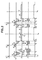
- the machine also includes generator means 3 and coils 4, connected to the generator means 3, for subjecting the body thus placed to radio frequency excitation sequences in the presence of disturbing field sequences: field gradients oriented along three reference axes of machine X, Y or Z ( Figure 2).
- the coils 4 represent the radio frequency coils and the field gradient coils at the same time.
- the machine also includes receiving means 5, connected to the coils 4, for receiving the magnetic resonance signal.
- means 6 can make it possible to calculate and store a first image l 1 and a second image 1 2 of a section 7 of the body 2.
- the two images relate to two series of experiments imposed by commands symbolized C 1 and C 2 of the generating means 3.
- comparison means 8 the images l 1 , 1 2 are compared point to point, and a third image Is is produced. This image 1 3 can be viewed on a device display 50.
- an image point, or pixel p conventionally represents by its brightness the density of particles contained in an element of volume, or voxel v which corresponds to it in section 7.
- the voxel v comprises numerous animated particles of velocities V comprising components V x , Vy and V z on each of the three reference axes of the machine.
- the invention will make it possible to calculate in the voxel v, and for all the other voxels also, the average speed and the number of the particles of this voxel thus in motion.
- Image 1 3 is representative of this speed information, by comparison between two images II and 1 2 where the effect of this speed will have been modulated in two different ways.
- FIG. 2 shows for this purpose radio frequency pulses 10, 11 and 12 applied in the presence of a so-called selection field gradient, for example oriented along the Z axis, and represented respectively by pulses 13, 14 and 15.
- the selection gradient is oriented along the Z axis the section is transverse, that is to say along an X, Y plane.
- the different acquired signals are phase coded. This is obtained by a variable intensity pulse of a so-called phase shifter gradient, with an axis perpendicular to a so-called reading gradient, the direction of which is constant.
- the reading gradient can be on the X axis and the phase shift gradient can be on the Y axis.
- the X gradient is rated 16
- the Y gradient is rated 17
- An improvement of this method can moreover make it possible to obtain images of several parallel sections simultaneously.
- precoding 17 which takes some time, postpones the measurement of the signal emitted by the body. As this signal fades very quickly, we imagined to measure an echo. This echo is produced, at the time of the application of the radiofrequency pulses 11 then 12 by a reflection of the phase dispersion of the contributions made by each of the particles. For this reason these pulses are drawn in FIG. 2 higher than the pulse 10 since they cause the orientation of the magnetic moments of the spins of the particles to be tilted by 180 ° whereas the pulse 10 had only tilted them by 90 ° .
- the phase shifter Y gradient varies stepwise succession s i fs starting from a certain value to the same value but of opposite sign. This value depends on the shape and the duration of the reading gradient 16.
- This phase shift gradient makes it possible to rotate each magnetic spin moment of a variable phase, depending on its ordinate along the Y axis and on the value of this gradient.
- the gradient Y can successively take the same number of values: in a preferred manner the definition of the two images will be the same.
- pulses 20 and 21 To avoid a parasitic precoding imposed by the end 18 of the pulse 13, for the part of this pulse existing after the end of the radiofrequency pulse 10, and by the beginning 19 of the read pulse 16 it is known to apply pulses 20 and 21 to these axes respectively.
- the time integral of these pulses is the same but of opposite sign, they neutralize the parasitic coding effect.
- the integral is understood in the sense of integral in time.
- the hatched areas 20 and 19 are therefore equal to the dashed areas 18 and 21 respectively.
- the pulses 20 and 21 do not interfere in the cut selection since at the time when they are applied the pulse 10 is no longer present.
- the pulses 14 and 15 are self-neutralized since they comprise portions 22 and 23 respectively, and 24 and 25 which are antisymmetrical with respect to the middle of the radiofrequency pulse, 11 and 12 for which they reselect the section 7 in the body. 2.
- the type 2 DFT imaging method is the most used in practice because of its speed of acquisition (compared to 3D methods) and its robustness against imperfections of the physical system, in particular vis- vis-à-vis the inhomogeneities of the orienting field. This is particularly appreciated in comparison with rear projection methods or with methods not using spin echo. In return, this method is the most intrinsically sensitive to the movement of particles.
- the immunity to inhomogeneities of the Bo field of the 2 DFT method stems from the fact that, unlike rear projection methods, the frequency encoder gradient is in the same direction (the reading gradient X) and of the same amplitude, G L , of a sequence to the other. The inhomogeneity of the Bo field then only distorts the isofrequency lines of resonance.
- the inhomogeneity of the field becomes the equivalent of a bad linearity of the reading gradient.
- the images are consequently distorted but without the creation of blurring and without the associated loss of resolution which one meets with the methods by rear projection.
- the reading gradient changes orientation with each sequence and therefore it distributes the inhomogeneities of the orienting field throughout the image for which it thus creates a blur.
- FIG. 3a shows the phase shift ⁇ resulting in the contribution of the signal emitted by two particles of the same voxel subjected to identical disturbances, when one of the particles (solid line) is stationary while the other particle (dashes) ) is driven by a speed V.
- FIG. 3a shows the time diagram of an RF radio frequency signal comprising a pulse 26 to create a spin echo.
- a magnetic field gradient was imposed by taking before and after the pulse 26, for example, a value G for a duration e each time.
- a value G for a duration e each time.
- In a given place to a previously excited, stationary particle vibrates at a frequency fo at the start of the application of the pulse 27.
- the duration e of this pulse 27 it vibrates at a different frequency.
- this frequency is higher, so that at the end of the pulse 27 it can be considered, since it resumes vibrating at the frequency fo that it has undergone a phase shift ⁇ 1.
- the radio frequency pulse 26 it can be assumed that everything happens as if the phase of the signal emitted by this particle were reversed: - 01 .
- the phase shift phenomenon continues: the contribution is still dephased by ⁇ 1. But this latter phase shift erases the effect of the first after it has been inverted by pulse 26. Consequently, the motionless particle in Io finds at the end of pulse 28 the phase it had at the start of the pulse 27.
- phase shift is proportional on the one hand to the amplitude of the gradient G and on the other hand to the duration during which each pulse of the gradient is imposed. More generally ⁇ 1 is proportional to the integral of this gradient during the duration of existence of its pulse if this pulse is not exactly square.
- G (r) therefore represents all the sequences required by the measurement. What characterizes the invention is that these sequences are maintained as they are but that their effects on the speed are compensated for by the addition of additional sequences of field gradients G 'called compensators such as where G 'represents gradients, also bipolar, i.e. such that In other words, by doing so we cancel the speed multiplier coefficient V which appears in the calculation of ⁇ (t). Suddenly, whatever this speed, ⁇ (t) is zero: all the contributions are in phase. Moving particles are taken into account as if they were fixed.
- each axis X, Y, Z the addition of such compensating bipolar gradients in the preferred form of pairs of pulses denoted 31 and 32, 33 and 34, 35 and 36, 37 and 38, 39 and 40 and 42 and 43.
- the incidence of these compensating impulses is symbolized in the drawing by the presence of small crosses. It is known, in the machines of the state of the art, to impose such pulses by modifying the commands C 1 or C 2 of the generating means.
- the time integral of the pulses of each couple is zero.
- the pulse 31 is applied during the same period.
- the measurement of the signal emitted is carried out between dates t'4 and t's contained between dates t 4 and t 5 and also during the duration of pulse 41.
- the compensation pulses applied on an axis , X, Y or Z are intended to erase the effect of the disturbing gradients applied on the same axis.
- the integral expression implicitly gives the gradients G '; it is possible to make simplifications. Firstly all the terms in G ( ⁇ ) . ⁇ are known terms (they belong to the 2DF T sequence): their integral is also. This integral can therefore be taken out of expression.
- the shapes of the compensating pulses 31 to 43 will be known shapes and, as far as possible, identical to shapes already practiced for the normal pulses of the disturbing sequences. Given the dates chosen for the application of these pulses, a unit integral of each of them can be calculated and the expression of G 'can be written in another way:
- the first member is known, it concerns disturbing gradients.
- the second member has integrals of gradients of preferred shape r and of unit amplitude. We know how to calculate the integral of the second member since we know the chosen form r. Consequently, we can deduce 1, that is to say the amplitude of the compensating pulses.
- FIG. 4 represents a flow tube 51 supposed to be in the examined section 7 of the body 2.
- the top of the figure represents a situation in which the axis of the tube 51 is located in the plane X, Y of the section. In the lower part of the figure the situation is different: the tube 51 is assumed to be perpendicular to the plane X and Y of the section.
- On both sides are represented voxels denoted 52 to 55. These voxels have the shape of rectangular parallelepipeds having a shape of substantially square section.
- the section is square insofar as, in the imagery, the representative sampling is carried out with the same resolution along the X axis and the Y axis of the section plane.
- the great length of the rectangular parallelepiped extends along the axis Z.
- This length is linked to the thickness of the section 7.
- This thickness is an experimental compromise between the fineness of resolution of the sections and the quantity of overall measurable signal. The thicker the cut, the higher the measurable signal, and of course the less precise the image. In practice, the large dimension is of the order of 7 to 15 mm, the square section is of the order of 1 mm by 1 mm.
- a fluid not shown circulates with a speed diagram 56.
- the speeds 57 of the particles located in the center are higher than the speeds 58 of the particles located on the edges of the duct.
- the speed 57 can be of the order of 50 cm per second.
- the voxels 52 and 53 comprise, when they are located directly above the section 59 of the conduit 51, necessarily animated particles with very different speeds.
- the spreading of the speed spectrum was so important that the contribution of voxels 52 and 53 in the overall signal was zero: one had the impression that the tube was hollow.
- the image of voxels 54 and 55 could in some cases be revealing.
- the effect of speed can be modulated with the method of the invention. It suffices not to completely cancel the multiplying coefficient of V in the expression of a ⁇ (i) where the compensating gradients are present.
- the modulation will be varied according to a particular axis. This particular axis can be the X axis, the Y axis, the Z axis, or even a different axis. To vary this modulation, the amplitude (1) of the compensation pulses applied to the X, Y, Z axes or to a combination of these axes is modified.
- the sensitivity to the speed effect is such that, for the nominal speed expected to be measured, the maximum phase difference is of the order of or less than a radian.
- the speed information is obtained simply by calculating the ratio of the relative variation of the measurements, from one experiment to another, to the measurement of the first (or second) experiment.
- S1 is the result of the first experiment
- S2 is the result of the second
- the average speed information is represented by (Si - S 2 ) / Si.
- the proposed calculation is no longer applicable as is to know the speed information, and on the other hand the sensitivity may be so strong that we would fall back into difficulties that the invention has resolved.
- the invention is implemented in an excitation method with gradient echo.
- This method is preferred to a method with spin echo as described so far.
- the radiofrequency pulse which makes the magnetic moments of the particles switch 180 ° has a slightly overvalued, redundant frequency band (of shorter duration), to properly rephasize the contributions of all the particles which had come into resonance because of the 90 ° pulse.
- This redundancy can in itself cause parasitic excitation of neighboring particles of wafer 7.
- these neighboring particles can be coded (by pulse 38 or 40). So the spurious signal they produce can vary from one sequence to another. Under these conditions, we no longer know how to extract it from the useful signal. If it remains constant indeed, by making a double acquisition, it can be deleted. If it is not removed, its presence can be troublesome.
Landscapes
- Physics & Mathematics (AREA)
- Health & Medical Sciences (AREA)
- Nuclear Medicine, Radiotherapy & Molecular Imaging (AREA)
- Vascular Medicine (AREA)
- General Health & Medical Sciences (AREA)
- Radiology & Medical Imaging (AREA)
- Engineering & Computer Science (AREA)
- Signal Processing (AREA)
- High Energy & Nuclear Physics (AREA)
- Condensed Matter Physics & Semiconductors (AREA)
- General Physics & Mathematics (AREA)
- Magnetic Resonance Imaging Apparatus (AREA)
Claims (15)
Applications Claiming Priority (4)
| Application Number | Priority Date | Filing Date | Title |
|---|---|---|---|
| FR8512352A FR2586296B1 (fr) | 1985-08-13 | 1985-08-13 | Procede de modulation de l'effet de la vitesse des parties mobiles d'un corps dans une mesure de densite par resonance magnetique nucleaire, et mise en oeuvre du procede pour en deduire la vitesse des parties mobiles concernees |
| FR8512352 | 1985-08-13 | ||
| US808049 | 1985-12-12 | ||
| US06/808,049 US4694253A (en) | 1985-08-13 | 1985-12-12 | Process for the modulation of the speed effect of moving parts of a body in a nuclear magnetic resonance density measurement and performance of the process in order to deduce therefrom the speed of the moving parts in question |
Publications (2)
| Publication Number | Publication Date |
|---|---|
| EP0216657A1 EP0216657A1 (de) | 1987-04-01 |
| EP0216657B1 true EP0216657B1 (de) | 1990-08-01 |
Family
ID=26224681
Family Applications (1)
| Application Number | Title | Priority Date | Filing Date |
|---|---|---|---|
| EP19860401788 Expired - Lifetime EP0216657B1 (de) | 1985-08-13 | 1986-08-08 | Modulationsverfahren des Geschwindigkeitseffekts von beweglichen Teilchen eines Körpers in einer Dichtemessung mittels der kernmagnetischen Resonanz |
Country Status (2)
| Country | Link |
|---|---|
| EP (1) | EP0216657B1 (de) |
| DE (1) | DE3673107D1 (de) |
Families Citing this family (3)
| Publication number | Priority date | Publication date | Assignee | Title |
|---|---|---|---|---|
| US4731583A (en) * | 1985-11-15 | 1988-03-15 | General Electric Company | Method for reduction of MR image artifacts due to flowing nuclei by gradient moment nulling |
| FR2621693A1 (fr) * | 1987-10-13 | 1989-04-14 | Thomson Cgr | Procede d'imagerie de mouvements intravoxels par rmn dans un corps |
| US5115812A (en) * | 1988-11-30 | 1992-05-26 | Hitachi, Ltd. | Magnetic resonance imaging method for moving object |
Family Cites Families (2)
| Publication number | Priority date | Publication date | Assignee | Title |
|---|---|---|---|---|
| US4516075A (en) * | 1983-01-04 | 1985-05-07 | Wisconsin Alumni Research Foundation | NMR scanner with motion zeugmatography |
| US4616180A (en) * | 1983-11-14 | 1986-10-07 | Technicare Corporation | Nuclear magnetic resonance imaging with reduced sensitivity to motional effects |
-
1986
- 1986-08-08 DE DE8686401788T patent/DE3673107D1/de not_active Expired - Fee Related
- 1986-08-08 EP EP19860401788 patent/EP0216657B1/de not_active Expired - Lifetime
Also Published As
| Publication number | Publication date |
|---|---|
| EP0216657A1 (de) | 1987-04-01 |
| DE3673107D1 (de) | 1990-09-06 |
Similar Documents
| Publication | Publication Date | Title |
|---|---|---|
| FR2546642A1 (fr) | Procede de generation d'images du temps de relaxation transversale en resonance magnetique nucleaire, par l'utilisation de sequences d'echos de spin multiples | |
| CH634412A5 (fr) | Appareil de determination des densites de noyaux par echo de spin pour elaboration de tomogrammes. | |
| EP0208601B1 (de) | Abbildungsverfahren mittels der kernmagnetischen Resonanz | |
| EP0315631B1 (de) | Eichkörper eines mit kernmagnetischer resonanz arbeitenden geräts und verfahren zur messung der charakteristiken eines magnetfeldes unter verwendung dieses eichkörpers | |
| US6552539B2 (en) | Method of correcting resonance frequency variation and MRI apparatus | |
| FR2769442A1 (fr) | Recepteur de radionavigation perfectionne, en particulier du type gps | |
| FR2520117A1 (fr) | Procede de compensation d'une oscillation acoustique dans des mesures de resonance magnetique nucleaire | |
| EP0312427B1 (de) | NMR Abbildungsverfahren für intravoxelle Bewegungen in einem Körper | |
| FR3054040A1 (fr) | Procede d’estimation d’une deviation angulaire moyenne entre l’axe magnetique et un axe de reference d’un objet magnetique | |
| EP0291387A1 (de) | Verfahren zur Flussmessung in einem magnetischen Kernspinresonanz-Experiment | |
| EP0188145A1 (de) | Verfahren zur Bildgebung durch Erzeugung und Verarbeitung von magnetischen Kernresonanzsignalen ohne Verzerrungen infolge Inhomogenitäten des Magnetfeldes | |
| FR2586296A1 (fr) | Procede de modulation de l'effet de la vitesse des parties mobiles d'un corps dans une mesure de densite par resonance magnetique nucleaire, et mise en oeuvre du procede pour en deduire la vitesse des parties mobiles concernees | |
| EP0216657B1 (de) | Modulationsverfahren des Geschwindigkeitseffekts von beweglichen Teilchen eines Körpers in einer Dichtemessung mittels der kernmagnetischen Resonanz | |
| FR2526968A1 (fr) | Procede de tomographie d'un objet par resonance magnetique nucleaire | |
| FR2630825A1 (fr) | Procede et dispositif pour la correction d'une degradation de phase provoquee par des courants parasites | |
| EP0245154B1 (de) | Verfahren zur Eichung der Amplitude der Hochfrequenzanregung eines Kernspintomographie-Gerätes | |
| WO2012076545A1 (fr) | Procédé de caractérisation d'échantillon solide par spectrométrie rmn et appareil pour la mise en oeuvre du procédé | |
| EP0242286B1 (de) | Eichungsverfahren einer Radiofrequenzanregung in einem NMR-Experiment | |
| EP0198748B1 (de) | Verfahren und Vorrichtung zur Bilderzeugung mittels magnetischer Kernresonanz | |
| WO1988000699A1 (fr) | Procede d'excitation radiofrequence dans une experimentation de rmn | |
| Ropele et al. | Super‐resolution MRI using microscopic spatial modulation of magnetization | |
| WO1990003583A1 (fr) | Machine de rmn a bas champ et a polarisation dynamique | |
| WO1988004046A1 (fr) | Procede de representation des parties en mouvement dans un corps par experimentation de resonance magnetique nucleaire | |
| JPH1033501A (ja) | 基本磁場の時間経過特性を求める方法 | |
| WO2019193271A1 (fr) | Procédé de calibration automatique d'un capteur d'arbre à cames pour corriger un faux rond de cible |
Legal Events
| Date | Code | Title | Description |
|---|---|---|---|
| PUAI | Public reference made under article 153(3) epc to a published international application that has entered the european phase |
Free format text: ORIGINAL CODE: 0009012 |
|
| AK | Designated contracting states |
Kind code of ref document: A1 Designated state(s): DE FR GB NL |
|
| 17P | Request for examination filed |
Effective date: 19870421 |
|
| 17Q | First examination report despatched |
Effective date: 19890420 |
|
| RAP1 | Party data changed (applicant data changed or rights of an application transferred) |
Owner name: GENERAL ELECTRIC CGR S.A. |
|
| GRAA | (expected) grant |
Free format text: ORIGINAL CODE: 0009210 |
|
| AK | Designated contracting states |
Kind code of ref document: B1 Designated state(s): DE FR GB NL |
|
| REF | Corresponds to: |
Ref document number: 3673107 Country of ref document: DE Date of ref document: 19900906 |
|
| GBT | Gb: translation of ep patent filed (gb section 77(6)(a)/1977) | ||
| PLBE | No opposition filed within time limit |
Free format text: ORIGINAL CODE: 0009261 |
|
| STAA | Information on the status of an ep patent application or granted ep patent |
Free format text: STATUS: NO OPPOSITION FILED WITHIN TIME LIMIT |
|
| 26N | No opposition filed | ||
| PGFP | Annual fee paid to national office [announced via postgrant information from national office to epo] |
Ref country code: FR Payment date: 19920724 Year of fee payment: 7 |
|
| PGFP | Annual fee paid to national office [announced via postgrant information from national office to epo] |
Ref country code: DE Payment date: 19920801 Year of fee payment: 7 |
|
| PGFP | Annual fee paid to national office [announced via postgrant information from national office to epo] |
Ref country code: GB Payment date: 19920803 Year of fee payment: 7 |
|
| PGFP | Annual fee paid to national office [announced via postgrant information from national office to epo] |
Ref country code: NL Payment date: 19920831 Year of fee payment: 7 |
|
| PG25 | Lapsed in a contracting state [announced via postgrant information from national office to epo] |
Ref country code: GB Effective date: 19930808 |
|
| PG25 | Lapsed in a contracting state [announced via postgrant information from national office to epo] |
Ref country code: NL Effective date: 19940301 |
|
| GBPC | Gb: european patent ceased through non-payment of renewal fee |
Effective date: 19930808 |
|
| NLV4 | Nl: lapsed or anulled due to non-payment of the annual fee | ||
| PG25 | Lapsed in a contracting state [announced via postgrant information from national office to epo] |
Ref country code: FR Effective date: 19940429 |
|
| PG25 | Lapsed in a contracting state [announced via postgrant information from national office to epo] |
Ref country code: DE Effective date: 19940503 |
|
| REG | Reference to a national code |
Ref country code: FR Ref legal event code: ST |