EP0216662B1 - Anordnung zur Überwachung einer Akkumulatorenbatterie - Google Patents
Anordnung zur Überwachung einer Akkumulatorenbatterie Download PDFInfo
- Publication number
- EP0216662B1 EP0216662B1 EP86401821A EP86401821A EP0216662B1 EP 0216662 B1 EP0216662 B1 EP 0216662B1 EP 86401821 A EP86401821 A EP 86401821A EP 86401821 A EP86401821 A EP 86401821A EP 0216662 B1 EP0216662 B1 EP 0216662B1
- Authority
- EP
- European Patent Office
- Prior art keywords
- battery
- circuit
- voltage
- capacity
- charge
- Prior art date
- Legal status (The legal status is an assumption and is not a legal conclusion. Google has not performed a legal analysis and makes no representation as to the accuracy of the status listed.)
- Expired - Lifetime
Links
- 230000032683 aging Effects 0.000 claims description 11
- 230000001276 controlling effect Effects 0.000 claims description 8
- 238000007599 discharging Methods 0.000 claims description 7
- 230000001105 regulatory effect Effects 0.000 claims description 7
- 230000004044 response Effects 0.000 claims description 5
- 238000004088 simulation Methods 0.000 claims description 4
- 230000001955 cumulated effect Effects 0.000 claims 1
- 230000033228 biological regulation Effects 0.000 description 13
- 238000012544 monitoring process Methods 0.000 description 7
- 238000011156 evaluation Methods 0.000 description 4
- 230000003321 amplification Effects 0.000 description 3
- 238000003199 nucleic acid amplification method Methods 0.000 description 3
- 238000005070 sampling Methods 0.000 description 3
- 230000008859 change Effects 0.000 description 2
- 230000007423 decrease Effects 0.000 description 2
- 230000003247 decreasing effect Effects 0.000 description 2
- 238000013475 authorization Methods 0.000 description 1
- OJIJEKBXJYRIBZ-UHFFFAOYSA-N cadmium nickel Chemical compound [Ni].[Cd] OJIJEKBXJYRIBZ-UHFFFAOYSA-N 0.000 description 1
- 239000003990 capacitor Substances 0.000 description 1
- 125000004122 cyclic group Chemical group 0.000 description 1
- 230000009849 deactivation Effects 0.000 description 1
- 230000001419 dependent effect Effects 0.000 description 1
- 238000001514 detection method Methods 0.000 description 1
- 238000010586 diagram Methods 0.000 description 1
- 230000005669 field effect Effects 0.000 description 1
- 238000009434 installation Methods 0.000 description 1
- 230000011664 signaling Effects 0.000 description 1
- 230000007704 transition Effects 0.000 description 1
- 238000004804 winding Methods 0.000 description 1
Images


Classifications
-
- G—PHYSICS
- G01—MEASURING; TESTING
- G01R—MEASURING ELECTRIC VARIABLES; MEASURING MAGNETIC VARIABLES
- G01R19/00—Arrangements for measuring currents or voltages or for indicating presence or sign thereof
- G01R19/165—Indicating that current or voltage is either above or below a predetermined value or within or outside a predetermined range of values
- G01R19/16533—Indicating that current or voltage is either above or below a predetermined value or within or outside a predetermined range of values characterised by the application
- G01R19/16538—Indicating that current or voltage is either above or below a predetermined value or within or outside a predetermined range of values characterised by the application in AC or DC supplies
- G01R19/16542—Indicating that current or voltage is either above or below a predetermined value or within or outside a predetermined range of values characterised by the application in AC or DC supplies for batteries
Definitions
- the present invention relates generally to a control device for monitoring parameters characterizing the state of a battery with a view to periodically recharging the battery with a high current and signaling any failure thereof.
- the invention relates to a device for controlling a storage battery comprising a speed monitoring circuit for supplying clock signal pulses having a variable frequency proportional to a charge and discharge current of the battery, a control circuit for estimating the instantaneous capacity of the battery as a function of counting-down counting of pulses of the clock signal, and a regulation circuit for recharging the battery from a mains voltage as soon as the instantaneous capacity is equal to a first capacity substantially lower than a maximum capacity of the battery.
- the instantaneous capacity of the battery in such a device is generally evaluated directly in proportion to the charging and discharging current.
- the available capacity of the battery is always less than the capacity of the charged battery.
- the ratio of available capacity to charged capacity called efficiency varies with temperature, especially when the battery is fully charged, and decreases rapidly when the ambient temperature increases.
- the self-discharge current increases all the more as the ambient temperature is high.
- an evaluation of the instantaneous capacity without considering the efficiency and the temperature underestimates and considerably alters the measure of capacity on which the cyclic recharging of the battery depends.
- the recharging of the battery be controlled as a function of the temperature so that the amplitude of the recharging current is all the more important the higher the temperature and the higher the energy efficiency of the battery. low.
- Application FR-A-2361754 discloses a battery control device as defined in the preamble of claim 1 and in which the aforementioned drawbacks of the prior art are partially avoided. Indeed, in the device according to FR-A-2361754 the influence of the temperature on the energy efficiency of the battery is taken into account. However, this influence is only taken into account during the charging regime and the estimation of the discharge current is not a function of the temperature.
- the present invention aims to provide a battery control device in which the drawbacks according to the prior art are completely eliminated and which is designed for optimal recharging of the battery as a function of a rate of battery overcharge and of the temperature.
- a battery control device is as defined and characterized in claim 1.
- control device also comprises an aging evaluation circuit for evaluating the aging of the battery by counting pulses whose repetition frequency depends on the temperature, the charge and discharge current, and the estimated capacity. of the battery, in order to produce and transmit an alarm signal when the number of pulses counted reaches a predetermined value.
- the regulation of the battery charge is carried out not only as a function of the amplitude of the charge and discharge current but also as a function of the temperature in order to obtain a suitable but not permanent overcharge.
- the control circuit periodically recharges the battery in particular in order to compensate for the self-discharge current varying with the temperature.
- the control circuit may include an up-down circuit having a maximum count representative of the maximum capacity of the battery for counting and counting the pulses of the clock signal, means for detecting said maximum count, means for detecting a first count in the up-down counting circuit representative of the first capacity, and means to authorize the means for recharging to recharge the battery as soon as the count of the up-down counting circuit is less than the first count, then as long as said count does not is not equal to the maximum count.
- the regulation circuit may include a charging current limiter including at the input a thermistor in parallel with a first contact, the first contact being closed when the battery is in discharge mode and has a capacity lower than the maximum capacity, and being open when the battery is in charge mode, and an amplifier having an input connected to an output of the current limiter and to the ground through a second contact controlled by the control circuit, a feedback input receiving said amplified voltage applied by the amplification circuit and proportional to a charge and discharge current, and an output connected to a control regulator control input, the second contact being open as soon as the battery capacity is less than said first capacity, then as long as the battery capacity is not equal to the maximum capacity.
- a charging current limiter including at the input a thermistor in parallel with a first contact, the first contact being closed when the battery is in discharge mode and has a capacity lower than the maximum capacity, and being open when the battery is in charge mode
- an amplifier having an input connected to an output of the current limiter and to the ground through a second contact controlled by the control
- the control device also monitors other parameters of the battery, as will be seen below, in order to prevent a discharge of the battery when the voltage at the terminals of the battery is less than a predetermined reference voltage and the capacity residual of the practically discharged battery is very small.
- the battery is considered "good" by the device, when the voltage at the terminals of the battery is around 60% of the voltage at full charge and the battery capacity is around 20% of the maximum initial capacity.
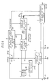
- a control device controlling a storage battery B essentially comprises a loop of circuits 1, 2 and 3 for recharging by automatic regulation of the battery, a discharge cut-off circuit 4 for disconnecting the battery B from a circuit of use, here represented by way of example by a load resistor R, and a life indication circuit 5.
- Most of the circuits included in the control device are supplied by a voltage converter CT supplying from the AC sector S a DC voltage of 5 Volts.
- a self-contained power source such as a 3 Volt "memoguard" P type battery, enabling the control device to last approximately 18 years, supplies electronic components in circuit 5 and also serves as a voltage source for reference, as we will see below.
- Typical numerical values are indicated in the following description by way of example, for a battery supporting high-current charging regimes, composed of five sealed cadmium-nickel cells, having a nominal voltage at rest of 6 Volts and a load voltage of 6.6 Volts.
- the control loop includes a battery charge or discharge rate monitoring circuit 1, a charge control circuit 2 and a charge regulation circuit 3.
- the monitoring circuit 1 detects a charge rate and a discharge rate of the battery by analyzing a current passing through a RS shunt resistor having a low ohmic value, typically of an Ohm, very low compared to that of the load resistor R.
- a charging current is drawn under a voltage of 10 Volts across a secondary winding of a transformer T connected to the sector S of 220 Volts and is rectified and regulated in the regulation circuit 3 to be applied to the battery B through the shunt resistor RS.
- discharge mode following an interruption of the mains, a discharge current produced by the battery B crosses the shunt resistor RS in a direction opposite to that of the charging current, and is supplied to the charging resistor R through the cut-off circuit 4 in the conducting state.
- the speed monitoring circuit 1 comprises a battery speed detector 10, a voltage sampling circuit 11, a self-discharge simulation circuit 12, a summing device 13, an amplification circuit 14 and a voltage-frequency converter 15.
- the detector 10 detects the direction of the current in the shunt resistor RS.
- a first output 10C of the detector 10 is in the high logic state "1" to indicate a charge rate of the battery B
- a second output 10D of the detector 10 is in the state "1" to indicate a discharge rate of the battery B.
- the detector 10 is essentially constituted by a voltage comparator including an operational amplifier 101 having two input terminals connected respectively to the terminals a and b of the resistor RS through resistors 102 and two substantially different input circuits with parallel resistance and capacitor 103, and having as output terminal, the output 10C connected to an inverter 104 with output 10D.
- the sampling circuit 11 comprises, at the input, a switching circuit having two pairs of simple parallel contacts 11 C and 11D, and at the output, an operational amplifier 111.
- the switching circuit takes the voltage across the shunt resistor RS through which circulates a charge or discharge current, and reverses this voltage in discharge mode so that the amplifier 111 amplifies the voltage taken whatever its polarity.
- the first and second contacts 11 C are closed when that the load indication output 10C is in the state "1""in order to connect the first and second terminals a and b respectively of the resistor RS through the resistors 102 to inverse input terminals" - "and direct "+” from amplifier 111 through two identical resistors 112.
- the first and second contacts 11 D are closed to connect the first and second terminals a and b of the resistor RS through the resistors 102 directly to the direct "+" and inverse "-" terminals of the amplifier 111.
- the amplifier 111 offers a gain inversely proportional to the sum of the ohmic values of the resistors 102, in parallel with resistors 103, and resistors 112, in charge mode, and inversely proportional to the ohmic value of resistors 102, in parallel with resistors 103, in discharge regime.
- Resistors 102, in parallel with resistors 103, and the resistors 112 are thus chosen to compensate for the drop in efficiency of the battery B, particularly in the vicinity of the maximum charge.
- the resistors 102, in parallel with the resistors 103, and the resistors 112 have ohmic values equal to 100 and 10 kOhm respectively, corresponding to an energy yield or ratio of maximum available capacity to charged capacity equal to 100/120.
- the resistors 112 can each be replaced by a non-linear component, such as a varistor, in order to adjust the load efficiency levels.
- a voltage proportional to a charge current corrected by the drop in efficiency of the battery, or to a discharge current is thus delivered by an output terminal 113 of the amplifier 111 to be applied to a direct input "+" of an operational amplifier 130 through an input resistor 131 in the adder 13.
- the amplifier 130 operates either as a subtractor when the battery is in charge mode, or as an adder when the battery is in discharge mode, in order to take into account has a permanent self-discharge of battery B.
- a thermistor 121 constituted by a resistance with negative temperature coefficient (CTN) having a terminal raised to 5 Volts. Another terminal of the thermistor 121 is connected on the one hand, to a reverse terminal "-" of the amplifier 130 through a contact 12C and a second input resistance 13C in the adder 13, and on the other hand, to the direct "+" terminal of the amplifier 130 through a contact 12D and a third input resistance 130 in the summator 13.
- CTN negative temperature coefficient
- the resistance-temperature variation characteristic of the thermistor 121 is chosen so that it is close an exponential characteristic self-discharge current-temperature of the battery B so that in the value of the charge or discharge current estimated by the monitoring circuit 1, the self-discharge current of the battery is taken into account.
- the charge or discharge current corrected by the loss of charge efficiency and the self-discharge current makes it possible to evaluate at any time the "theoretical" capacity of the battery in the control circuit of charge 2.
- the contact 12C like the contacts 11C, is closed under load conditions under the control of the output 10C of the speed detector 10, which puts the adder 13 in subtractor operation; the adder subtracts a "self-discharge” voltage established by the thermistor 121 from the "charge” voltage supplied by the amplifier 111 to obtain a "theoretical charge” voltage supplied by an output of the amplifier 130.
- discharge the contact 12D like the contacts 11 D is closed under the control of the output 10D of the speed detector 10; the adder then operates as an adder to add the "discharge” voltage supplied by the amplifier 111 and the "self-discharge” voltage into a "theoretical discharge” voltage supplied by the output of the amplifier 130.
- the theoretical charge or discharge voltage is amplified in the amplification circuit 14 including a non-inverting operational amplifier 141 and is converted linearly to frequency in the voltage-frequency converter 15.
- the converter 15 operates linearly over three decades of frequency and provides at an output 151 a clock signal typically having a frequency between 1.2 Hz and 1.2 kHz.
- the frequency of. the clock signal is greater the greater the theoretical charge current in order to rapidly recharge the battery and avoid inadvertent overcharging of the battery, or the greater the theoretical discharge current in order to rapidly stop any discharge of the battery as soon as the instantaneous capacity of the battery reaches a theoretical discharge threshold fixed at not more than 20% of its nominal theoretical capacity.
- the clock signal has a relatively low frequency proportional to the simulated self-discharge current.
- the charge control circuit 2 comprises a frequency divider 21, an up-down counting circuit 22 with a maximum count equal to 99 and a recharging authorization logic circuit 23.
- the frequency divider 21 divides the variable frequency of the clock signal delivered by the output 151 of the voltage-frequency converter 15 typically by 2 19 .
- the divider 21 applies a second clock signal having frequencies between 2.3 and 10- 6 2.3 10- 3 Hz to clock inputs C of two decimal up-down counters 22u and 22d in circuit 22.
- the up-down counters 22u and 22d produce by four respective outputs Qo, 0 1 , Q 2 and Q 3 a digit of the units and a digit of the tens coded in binary code, constituting a clock pulse count of the second clock signal representing the "theoretical" instantaneous capacity of battery B.
- the output 10C of the speed detector 10 puts in the state "1" U / D up / down counting inputs of the up and down counters 22u and 22d so that these count pulses of the second clock signal until the capacity maximum of the battery is reached and corresponds to a count equal to 99.
- the output 10C of the speed detector 10 is always in the state "0" and commands a countdown pulses of the second clock signal. This countdown can be stopped as soon as the battery capacity has decreased to a determined percentage, equal to 90%, of its maximum capacity following the triggering of a battery recharge by the logic circuit 23.
- the logic circuit 23 includes two NAND gates 231 u and 231 d each having two inputs connected directly to the outputs Qo and Q 3 of the respective up-down counter 22u, 22d and two other inputs connected to the outputs Q 1 and Q 2 of the counter- respective down-counter through inverters 232u and 233u, 232d and 233d, in order to detect the digits of the units and tens of the pulse count equal to 9.
- the circuit 23 also includes a flip-flop JK 234 having a clock input C connected to the output of the divider 21 through an inverter 235, an input J connected to the outputs of the gates 231 u and 231 d through a NOR gate with two inputs 236, and an input K connected directly to the output of the door 231 d.
- a flip-flop JK 234 having a clock input C connected to the output of the divider 21 through an inverter 235, an input J connected to the outputs of the gates 231 u and 231 d through a NOR gate with two inputs 236, and an input K connected directly to the output of the door 231 d.
- the inputs J and K are respectively in the states “1 and” 0 "and following a pulse on the input C of the flip-flop a output Q of flip-flop 234 goes to state “1" in order to deactivate the charge regulation circuit 3 and thus avoid overcharging the battery B.
- This deactivation is obtained by closing a contact 318 setting the potential of earth an input of regulation circuit 3 as will be seen below.
- the instantaneous capacity of the battery decreases from 99% to 90%, the input J goes to state "0” and blocks output Q in state "1", whatever the pulses applied to input C.
- the charge regulation circuit 3 comprises a charge current limiter 31, an automatic charge control circuit 32 and a charge regulator 33.
- the load current limiter 31 includes a non-inverting operational amplifier 311 connected to an input circuit supplying a temperature-dependent voltage by means of a negative temperature coefficient thermistor 312.
- the thermistor 312 is inserted between a resistor 313 brought to 5 Volts and a resistor 314 brought to earth, a common terminal to the resistor 314 and to the thermistor 312 being connected to a direct input terminal "+" "of the amplifier 311 via a resistor 315.
- a contact 316 is connected in parallel to the thermistor 312 and is controlled by an OR logic circuit 317 having a first input connected to the output 10D of the speed detector 10 and a second input connected to a cascading output Cost of the up-down counter 22d. Cost output of each up-down counter 22 ⁇ , 22d is in the "0" state when the digit of the units or tens is equal to 9.
- the already mentioned contact 318 controlled by the output Q of the flip-flop 234 is interconnected between the earth and an output terminal of the amplifier 311 connected to a direct input "+" of an operational amplifier 321 included in the control circuit 32
- an inverse input "-" of the amplifier 321 is connected to a terminal of a feedback resistor 322 and to the output 113 of the amplifier 111 in the voltage sampling circuit 11 via a resistor 323.
- the charge regulator 33 is a current regulator comprising a field effect transistor 331 and a bipolar NPN transistor 332 having respectively a drain and a collector connected to the transformer T through a rectifier diode 333 and to a terminal of the load resistance R, and having a source and a base connected together.
- the gate of transistor 331 is connected to an output terminal of amplifier 321 via a input resistance 334.
- the emitter of transistor 332 is connected to an input terminal 41 of the discharge cut-off circuit 4 and to the positive terminal B + of battery B via the shunt resistor RS.
- control contact 318 is opened as soon as the battery capacity is less than 90% of its maximum capacity.
- the transition to the charge mode indicated by the state "0" at the output 10D opens the contact 316, the cost output of the up-down counter 22d being in the state "0 "that is to say the loaded capacity being greater than or equal to 90%.
- the thermistor 312 then intervenes to impose a reference voltage as a function of temperature at the direct input of the control amplifier 321 which is a function of the temperature and which is amplified by the charge level imposed by the output 113 of the amplifier 111.
- the current limiter 31 thus limits any overload current as a function of the temperature.
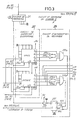
- the discharge cut-off circuit 4 is also shown in Fig. 4. It includes a switch in the form of a Darlington circuit with two PNP transistors 42 and 43, interconnected between terminal 41 and the use resistance R to cut off the discharge of the battery when its voltage drops below a so-called stop voltage.
- the circuit 4 also includes a voltage comparator including an operational amplifier 44.
- the amplifier 44 compares a reference voltage equal to the voltage of the battery P and applied to a direct input terminal "+" "of the amplifier 44 with a voltage applied to an inverse input terminal "-" of the amplifier 44 and established by a voltage divider 45 connected to the battery B.
- the value of the stop voltage is for example fixed at approximately 75% of the nominal voltage across the terminals of the battery.
- the output of the amplifier 44 is connected to a base of the Darlington circuit via a resistor 46 and thus blocks the transistors 42-43 to disconnect the battery B from the use resistor R when the voltage at the input of amplifier 44 becomes lower than the battery voltage (3 volts), that is to say when the voltage across the battery drops below 4.5 volts. do, the fraction of voltage taken by l
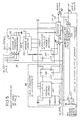
- the service life indication circuit 5 shown in FIG. 5 makes it possible to indicate, among other things, an impending discharge of the battery thanks to an alarm signal.
- the circuit 5 comprises an end of discharge detection circuit 51 including an operational amplifier 511 having a direct input "+ connected to the battery P and an inverse input” - “connected to the battery B through a divider of voltage 512.
- the amplifier 511 will react as described below, when the voltage delivered by the battery B drops below a predetermined threshold, designated "alarm voltage", greater than the stop voltage and substantially equal to 83% of the nominal voltage of the battery.
- the output signal of the amplifier 511 is supplied to an input of an AND gate 513 with three inputs. Two other inputs of gate 513 are connected to output 10D of the speed detector and to an output of an OR gate 514 respectively.
- Gate 514 has three inputs connected to outputs Qi, Q 2 and Q 3 of up-down counter 22d in order to detect an instantaneous capacity of at least 20% of the nominal theoretical capacity of battery B.
- gate ET 513 will transmit a loss of capacity alarm pulse, if the battery voltage B reaches the alarm threshold before the information at the output of gate OR 514 is significant for a discharge 80% of the nominal capacity of the battery.
- the alarm pulse is transmitted via an OR gate with two inputs 52.
- the service life indication circuit 5 comprises means 53-54 for evaluating charge-discharge cycles of the battery and aging of the battery as a function of temperature, in order to report an upcoming battery B failure.
- a charge-discharge cycle evaluation circuit 53 is intended to evaluate both the number of charge-discharge cycles and the depth of the cycles, these two parameters reducing the useful life of the battery B.
- the circuit 53 includes a programmable frequency divider 531, a frequency divider by 2 18 532 and a D flip-flop 533.
- the frequency divider 531 receives by a clock input C the clock signal delivered by the output 151 of the voltage-frequency converter 15 and having a frequency proportional to the intensity of the charge or discharge current, and by an address bus connected to the outputs Qo to Q 3 of the second up-down counter 22d, the capacity of the battery to within 10%.
- An output 534 of the programmable divider 531 provides at the input of the frequency divider 532 a depth of discharge signal having a frequency inversely proportional to the battery capacity and reduced compared to the charge or discharge clock signal, and thus d 'the greater the lower the battery capacity for a given discharge or charge current.
- the depth signal is applied to a clock input C of the flip-flop 533 having an output Q connected to a reset input R in order to put in the form of pulses with constant width the depth of discharge signal.
- a counter 55 counts the pulses of the depth signal delivered by the output Q of the flip-flop 533 via an OR gate with two inputs 56.
- a variable frequency oscillator 541 and a D flip-flop 542 are provided.
- the aging signal delivered by the oscillator 541 is applied to a clock input C of the flip-flop 542 having an output Q connected to an input R.
- the pulses of the aging signal shaped by the flip-flop 542 are also transmitted to the counter 55 via OR gate 56.
- the counter 55 has a maximum account representing the life of the battery, that is to say both its operating time and a number of charge cycles - discharge that it can undergo during this period.
- an output of the counter 55 signals an "end of life" of the battery via the OR gate 52.
- the division ratios in the divider programmable 531 are higher the greater the depths of discharge.
- the depth signal includes 100 to 211, 646 to 846 and 1429 to 1929 pulses for a given discharge current. 7.3.10 10 pulses of the discharge depth signal signal for example 1800 discharge-charge cycles with a depth of 50%, translated by a change of state of the output of the counter 55.
- the output of the amplifier 44 in the cut-off circuit (FIG. 4) and the output of a resistance-capacitance circuit 47 for detecting a power cut are connected via a gate 48, to the reset inputs R of the up-down counters 22u and 22d (Fig. 3) in order to reinitialize the device when the battery B is at the end of discharge or is replaced by a new battery.
- the counter 55 is also reset to zero in the event of a battery change.
Landscapes
- Engineering & Computer Science (AREA)
- Power Engineering (AREA)
- Physics & Mathematics (AREA)
- General Physics & Mathematics (AREA)
- Charge And Discharge Circuits For Batteries Or The Like (AREA)
- Secondary Cells (AREA)
Claims (16)
Applications Claiming Priority (2)
| Application Number | Priority Date | Filing Date | Title |
|---|---|---|---|
| FR8512679 | 1985-08-23 | ||
| FR8512679A FR2586482B1 (fr) | 1985-08-23 | 1985-08-23 | Dispositif de controle d'une batterie d'accumulateurs |
Publications (2)
| Publication Number | Publication Date |
|---|---|
| EP0216662A1 EP0216662A1 (de) | 1987-04-01 |
| EP0216662B1 true EP0216662B1 (de) | 1991-05-02 |
Family
ID=9322365
Family Applications (1)
| Application Number | Title | Priority Date | Filing Date |
|---|---|---|---|
| EP86401821A Expired - Lifetime EP0216662B1 (de) | 1985-08-23 | 1986-08-14 | Anordnung zur Überwachung einer Akkumulatorenbatterie |
Country Status (6)
| Country | Link |
|---|---|
| US (1) | US4803416A (de) |
| EP (1) | EP0216662B1 (de) |
| JP (1) | JPS6289430A (de) |
| CA (1) | CA1244080A (de) |
| DE (1) | DE3679021D1 (de) |
| FR (1) | FR2586482B1 (de) |
Families Citing this family (59)
| Publication number | Priority date | Publication date | Assignee | Title |
|---|---|---|---|---|
| DE3821808C2 (de) * | 1988-06-28 | 1994-06-16 | Helmut Haendel & Partner Mesda | Verfahren und Vorrichtung zum automatischen Testen von Akkumulatoren einer unterbrechungsfreien Stromversorgungsanlage |
| FR2652202B1 (fr) * | 1989-09-21 | 1996-10-25 | Marjana Pretnar | Procede d'analyse de l'etat de charge des batteries. |
| US6377028B1 (en) | 1990-10-23 | 2002-04-23 | Texas Instruments Incorporated | System for charging monitoring batteries for a microprocessor based method |
| US5432429A (en) * | 1990-10-23 | 1995-07-11 | Benchmarq Microelectronics, Inc. | System for charging/monitoring batteries for a microprocessor based system |
| FR2672713A1 (fr) * | 1991-02-13 | 1992-08-14 | Inst Nat Polytech Grenoble | Composant d'alimentation du type carte de credit. |
| US5253300A (en) * | 1991-03-22 | 1993-10-12 | H. C. Knapp Sound Technology Inc. | Solar powered hearing aid |
| DE4112987C2 (de) * | 1991-04-20 | 1995-02-23 | Bosch Gmbh Robert | Vorrichtung zur Bestimmung des Ladezustands einer wiederaufladbaren Batterie |
| AT405887B (de) * | 1991-04-20 | 1999-12-27 | Bosch Gmbh Robert | Vorrichtung zur bestimmung des ladezustands einer wiederaufladbaren batterie |
| AT398142B (de) * | 1991-05-24 | 1994-09-26 | Elin Energieanwendung | Verfahren zur bestimmung des ladezustandes einer zink-brom-batterie sowie verfahren zum laden derselben |
| JP2593253B2 (ja) * | 1991-05-29 | 1997-03-26 | 富士通株式会社 | 電流測定回路 |
| US5233283A (en) * | 1991-12-04 | 1993-08-03 | John Kennedy | Light curing device power control system |
| US5315228A (en) * | 1992-01-24 | 1994-05-24 | Compaq Computer Corp. | Battery charge monitor and fuel gauge |
| US5357203A (en) * | 1992-07-08 | 1994-10-18 | Benchmarq Microelectronics, Inc. | Battery monitoring circuit for operating with high battery discharge rates |
| US5440221A (en) * | 1992-07-08 | 1995-08-08 | Benchmarg Microelectronics, Inc. | Method and apparatus for monitoring batttery capacity with charge control |
| US5284719A (en) * | 1992-07-08 | 1994-02-08 | Benchmarq Microelectronics, Inc. | Method and apparatus for monitoring battery capacity |
| US5223780A (en) * | 1992-07-14 | 1993-06-29 | Stephen Hu | Mobile telephone battery power supply unit with power detection and discharge circuit |
| FR2694637B1 (fr) * | 1992-08-05 | 1994-10-07 | Merlin Gerin | Procédé de détermination du temps d'autonomie d'une batterie. |
| US5592069A (en) * | 1992-10-07 | 1997-01-07 | Dallas Semiconductor Corporation | Battery charger |
| US5467006A (en) * | 1992-12-21 | 1995-11-14 | Ford Motor Company | Energy transfer device and method |
| US5539298A (en) * | 1993-03-19 | 1996-07-23 | Compaq Computer Corporation | Pulse charge technique to trickle charge a rechargeable battery |
| US5514946A (en) * | 1993-03-19 | 1996-05-07 | Compaq Computer Corp. | Battery pack including static memory and a timer for charge management |
| US6064819A (en) * | 1993-12-08 | 2000-05-16 | Imec | Control flow and memory management optimization |
| JPH07284233A (ja) * | 1994-04-05 | 1995-10-27 | Sony Corp | 充電方法及び充電装置 |
| US5606242A (en) * | 1994-10-04 | 1997-02-25 | Duracell, Inc. | Smart battery algorithm for reporting battery parameters to an external device |
| US5633573A (en) * | 1994-11-10 | 1997-05-27 | Duracell, Inc. | Battery pack having a processor controlled battery operating system |
| US6114833A (en) * | 1995-04-14 | 2000-09-05 | Lester Electrical Of Nebraska, Inc. | Monitoring and controlling system for battery and battery charger |
| US5617008A (en) * | 1995-06-20 | 1997-04-01 | Motorola, Inc. | Method, apparatus, and communication device for charging a charge storage device which is momentarily connected to a fixed load |
| US5641587A (en) * | 1995-12-15 | 1997-06-24 | Compaq Computer Corporation | Battery pack with a monitoring circuit for a known system |
| US5903137A (en) * | 1995-12-15 | 1999-05-11 | Compaq Computer Corporation | Battery pack with single charge inhibit/regulator transistor |
| US5764028A (en) * | 1995-12-15 | 1998-06-09 | Compaq Computer Corporation | Battery pack with single charge-inhibit/regulator transistor |
| US5831350A (en) * | 1995-12-15 | 1998-11-03 | Compaq Computer Corporation | System using interchangeable nickel-based and lithium ion battery packs |
| US5721482A (en) * | 1996-01-16 | 1998-02-24 | Hewlett-Packard Company | Intelligent battery and method for providing an advance low battery warning for a battery powered device such as a defibrillator |
| US5677077A (en) * | 1996-02-22 | 1997-10-14 | Compaq Computer Corporation | Sensor circuit for providing maximum and minimum cell voltages of a battery |
| EP0958632A4 (de) * | 1996-07-17 | 2002-03-06 | Duracell Inc | Betriebssystem für batterie |
| KR19980065966A (ko) * | 1997-01-17 | 1998-10-15 | 김광호 | 배터리 용량 표시장치 |
| DE19718781A1 (de) * | 1997-05-03 | 1998-11-05 | Vb Autobatterie Gmbh | Elektrischer Akkumulator |
| US6025695A (en) * | 1997-07-09 | 2000-02-15 | Friel; Daniel D. | Battery operating system |
| DE19803817C5 (de) * | 1998-01-31 | 2005-11-03 | Meloh Armaturen Ruppel & Meloh Gmbh | Armatur, insbesondere Wasserarmatur |
| MY125512A (en) * | 1999-03-05 | 2006-08-30 | Sony Corp | Battery pack, method for charging/discharging counting and method for setting residual capacity of the battery pack |
| US6121755A (en) * | 1999-06-03 | 2000-09-19 | Illinois Tool Works Inc. | Optical-electronic battery indicator |
| US6191556B1 (en) * | 1999-10-12 | 2001-02-20 | International Business Machines Corporation | Method and apparatus for estimating the service life of a battery |
| US6236214B1 (en) * | 1999-12-23 | 2001-05-22 | Ericsson Inc. | Method and apparatus for determining the remaining operation time of a mobile communication unit |
| JP4553567B2 (ja) * | 2003-04-25 | 2010-09-29 | 三洋電機株式会社 | 電池充放電監視用回路、及び電池充放電監視方法 |
| EP2270526A1 (de) | 2003-07-09 | 2011-01-05 | Premium Power Corporation | Vorrichtung zum Überwachung und zur Ladung einer Ausgewählten Gruppe von Batterienzellen |
| US20050248319A1 (en) * | 2004-05-05 | 2005-11-10 | Dell Products L.P. | Battery failure discharge apparatus |
| CN1862281B (zh) * | 2005-05-10 | 2010-10-27 | 电池公司 | 电池管理系统及具有运行时间分析报告功能的装置 |
| JP4640391B2 (ja) * | 2007-08-10 | 2011-03-02 | トヨタ自動車株式会社 | 電源システムおよびそれを備えた車両 |
| US8044640B2 (en) | 2008-10-07 | 2011-10-25 | Black & Decker Inc. | Method for stepping current output by a battery charger |
| DE102009049589A1 (de) * | 2009-10-16 | 2011-04-21 | Bayerische Motoren Werke Aktiengesellschaft | Verfahren zur Bestimmung und/oder Vorhersage der maximalen Leistungsfähigkeit einer Batterie |
| CN102759713B (zh) * | 2011-04-29 | 2015-08-26 | 比亚迪股份有限公司 | 一种电池能量效率测试装置及其测试方法 |
| KR101428293B1 (ko) * | 2012-12-18 | 2014-08-07 | 현대자동차주식회사 | 전기자동차용 보조배터리의 주기적 충전 방법 |
| DE202015106539U1 (de) | 2015-12-01 | 2017-03-06 | Rp-Technik Gmbh | Zustandsindikator und Kommunikationssystem zur Kontrolle von Akkumulatoren |
| WO2018076301A1 (zh) * | 2016-10-28 | 2018-05-03 | 深圳市大疆创新科技有限公司 | 电池的控制方法、系统和电池 |
| DE102017107070A1 (de) | 2017-04-03 | 2018-10-04 | AccuPower Forschungs-, Entwicklungs- und Vertriebsgesellschaft mbH | Kaskadierbare anordnung zum verschalten einer vielzahl von energiespeichern sowie verfahren zur steuerung der energieversorgung bei diesen energiespeichern |
| CN112415294B (zh) | 2019-08-22 | 2024-11-19 | 上海中兴软件有限责任公司 | 电压瞬间下降的检测电路及车载诊断系统 |
| CN112782484B (zh) * | 2019-11-05 | 2025-02-07 | 大唐恩智浦半导体有限公司 | 检测电路和集成电路 |
| KR102862005B1 (ko) | 2019-12-04 | 2025-09-18 | 주식회사 엘지에너지솔루션 | 배터리 관리 시스템, 배터리 관리 방법 및 배터리 팩 |
| EP4457530B1 (de) * | 2022-07-07 | 2026-04-29 | Samsung Electronics Co., Ltd. | Verfahren und elektronische vorrichtung zur vorhersage der verbleibenden lebensdauer einer batterie |
| CN120742105B (zh) * | 2025-04-09 | 2026-01-30 | 赣州康晋储能技术有限公司 | 一种电池健康监测预警方法及系统 |
Family Cites Families (12)
| Publication number | Priority date | Publication date | Assignee | Title |
|---|---|---|---|---|
| GB1437025A (en) * | 1972-08-30 | 1976-05-26 | Deutsche Automobilgesellsch | Method and device for determining the state of charge of galvanic energy sources |
| US3979657A (en) * | 1973-05-15 | 1976-09-07 | Westinghouse Electric Corporation | Battery monitor with automatic scale and recycle prevents |
| GB1432318A (en) * | 1973-07-04 | 1976-04-14 | Vdo Schindling | Apparatus for determining the state of charge of accumulator |
| US4012681A (en) * | 1975-01-03 | 1977-03-15 | Curtis Instruments, Inc. | Battery control system for battery operated vehicles |
| FR2361754A1 (fr) * | 1976-08-11 | 1978-03-10 | Accumulateurs Fixes | Procede et dispositif de controle de la charge et de la decharge d'une batterie d'accumulateurs |
| FR2443686A1 (fr) * | 1978-12-07 | 1980-07-04 | Accumulateurs Fixes | Procede et dispositif de suivi de l'etat de charge d'un accumulateur |
| JPS5648076A (en) * | 1979-09-25 | 1981-05-01 | Toshiba Corp | Battery control circuit |
| US4388618A (en) * | 1981-01-07 | 1983-06-14 | Curtis Instruments, Inc. | Battery state of charge indicator operating on bidirectional integrations of terminal voltage |
| FR2534381B1 (fr) * | 1982-10-12 | 1985-05-31 | Peugeot Cycles | Appareil indicateur de charge et de decharge de batterie electrique |
| GB2147109A (en) * | 1983-07-28 | 1985-05-01 | Warman Int Ltd | Battery charge monitor |
| US4638237A (en) * | 1985-01-03 | 1987-01-20 | Pulse Electronics, Inc. | Battery condition indicator |
| US4679000A (en) * | 1985-06-20 | 1987-07-07 | Robert Clark | Bidirectional current time integration device |
-
1985
- 1985-08-23 FR FR8512679A patent/FR2586482B1/fr not_active Expired
-
1986
- 1986-08-14 EP EP86401821A patent/EP0216662B1/de not_active Expired - Lifetime
- 1986-08-14 DE DE8686401821T patent/DE3679021D1/de not_active Expired - Lifetime
- 1986-08-20 US US06/898,392 patent/US4803416A/en not_active Expired - Lifetime
- 1986-08-21 CA CA000516542A patent/CA1244080A/en not_active Expired
- 1986-08-22 JP JP61195742A patent/JPS6289430A/ja active Pending
Also Published As
| Publication number | Publication date |
|---|---|
| US4803416A (en) | 1989-02-07 |
| FR2586482B1 (fr) | 1988-02-19 |
| FR2586482A1 (fr) | 1987-02-27 |
| JPS6289430A (ja) | 1987-04-23 |
| CA1244080A (en) | 1988-11-01 |
| DE3679021D1 (de) | 1991-06-06 |
| EP0216662A1 (de) | 1987-04-01 |
Similar Documents
| Publication | Publication Date | Title |
|---|---|---|
| EP0216662A1 (de) | Anordnung zur Überwachung einer Akkumulatorenbatterie | |
| EP1854165B3 (de) | Verfahren zum ausgewogenen aufladen einer lithiumionen- oder lithium-polymer-batterie | |
| EP1685622B3 (de) | Gleichgewichts-ladeverfahren für eine lithiumionen- oder lithiumpolymerbatterie | |
| CA1134433A (fr) | Procede et dispositif de suivi de l'etat de charge d'un accumulateur | |
| EP1079525B1 (de) | System zur Steuerung eines Zweirichtungs-Schalters mit zwei Transistoren | |
| EP2721684B1 (de) | Batteriezellensystem mit vereinfachter überwachung | |
| EP1158647A1 (de) | Verfahren und Gerät zum Ladeausgleich einer Vielzahl in Serie geschalteter Batteriezellen | |
| EP0343056A1 (de) | Automatische Ladeeinrichtung für Batterien oder Akkus | |
| FR2722031A1 (fr) | Dispositif regulateur pour batterie d'accumulateurs electriques | |
| EP4189406B1 (de) | Batterieverwaltungssystem | |
| FR2605415A1 (fr) | Appareil de controle de l'etat de charge d'une pile | |
| FR2951331A1 (fr) | Systeme et procede de gestion de charge d'une batterie | |
| EP0009606B1 (de) | Vorrichtung zum Steuern der Ladung einer Batterie | |
| EP1825557B1 (de) | Verfahren zur steuerung einer wiederaufladbaren batterie und wiederaufladbare batterie zur ausführung des verfahrens | |
| FR2474776A1 (fr) | Appareil pour la charge d'une batterie rechargeable | |
| EP0021867A1 (de) | Gegen Schwankungen der Eingangsspannung und der Ausgangsleistung geregelte Zerhacker-Spannungsversorgungsschaltung, insbesondere für Fernsehempfänger | |
| FR2635931A1 (fr) | Dispositif de protection d'un modulateur a ligne a retard | |
| EP1432096A2 (de) | Konstantspannung-Ladungszustandsteuervorrichtung für eine Einheit mit sekundären elektrochemischen Generatoren | |
| FR3106447A1 (fr) | Element de stockage d’energie electrique et alimentation sauvegardee associee | |
| FR2480524A1 (fr) | Chargeur de batterie d'accumulateurs electriques | |
| FR2978625A1 (fr) | Methode et dispositif d'equilibrage des batteries d'accumulateurs electriques | |
| FR2638585A1 (fr) | Chargeur pour accumulateur cadmium-nickel | |
| FR2719722A1 (fr) | Appareil d'alimentation électrique utilisable notamment comme alimentation de sauvegarde. |
Legal Events
| Date | Code | Title | Description |
|---|---|---|---|
| PUAI | Public reference made under article 153(3) epc to a published international application that has entered the european phase |
Free format text: ORIGINAL CODE: 0009012 |
|
| AK | Designated contracting states |
Kind code of ref document: A1 Designated state(s): DE GB IT NL SE |
|
| 17P | Request for examination filed |
Effective date: 19870325 |
|
| 17Q | First examination report despatched |
Effective date: 19890629 |
|
| ITF | It: translation for a ep patent filed | ||
| GRAA | (expected) grant |
Free format text: ORIGINAL CODE: 0009210 |
|
| AK | Designated contracting states |
Kind code of ref document: B1 Designated state(s): DE GB IT NL SE |
|
| REF | Corresponds to: |
Ref document number: 3679021 Country of ref document: DE Date of ref document: 19910606 |
|
| GBT | Gb: translation of ep patent filed (gb section 77(6)(a)/1977) | ||
| PLBI | Opposition filed |
Free format text: ORIGINAL CODE: 0009260 |
|
| 26 | Opposition filed |
Opponent name: ROBERT BOSCH GMBH Effective date: 19920125 |
|
| NLR1 | Nl: opposition has been filed with the epo |
Opponent name: ROBERT BOSCH GMBH. |
|
| PLAB | Opposition data, opponent's data or that of the opponent's representative modified |
Free format text: ORIGINAL CODE: 0009299OPPO |
|
| R26 | Opposition filed (corrected) |
Opponent name: ROBERT BOSCH GMBH Effective date: 19920125 |
|
| EAL | Se: european patent in force in sweden |
Ref document number: 86401821.3 |
|
| RAP2 | Party data changed (patent owner data changed or rights of a patent transferred) |
Owner name: AUDRAIN, ERIC Owner name: FRANCE TELECOM |
|
| RIN2 | Information on inventor provided after grant (corrected) | ||
| RAP2 | Party data changed (patent owner data changed or rights of a patent transferred) |
Owner name: FRANCE TELECOM |
|
| RIN2 | Information on inventor provided after grant (corrected) |
Free format text: ABIVEN, JACQUES * AUDRAIN, ERIC |
|
| NLT2 | Nl: modifications (of names), taken from the european patent patent bulletin |
Owner name: FRANCE TELECOM TE PARIJS EN ERIC AUDRAIN TE PERROS |
|
| NLT1 | Nl: modifications of names registered in virtue of documents presented to the patent office pursuant to art. 16 a, paragraph 1 |
Owner name: FRANCE TELECOM TE PARIJS, FRANCE |
|
| NLS | Nl: assignments of ep-patents |
Owner name: FRANCE TELECOM |
|
| REG | Reference to a national code |
Ref country code: GB Ref legal event code: 732E |
|
| APAC | Appeal dossier modified |
Free format text: ORIGINAL CODE: EPIDOS NOAPO |
|
| APAC | Appeal dossier modified |
Free format text: ORIGINAL CODE: EPIDOS NOAPO |
|
| PLBN | Opposition rejected |
Free format text: ORIGINAL CODE: 0009273 |
|
| STAA | Information on the status of an ep patent application or granted ep patent |
Free format text: STATUS: OPPOSITION REJECTED |
|
| 27O | Opposition rejected |
Effective date: 19990419 |
|
| REG | Reference to a national code |
Ref country code: GB Ref legal event code: IF02 |
|
| PGFP | Annual fee paid to national office [announced via postgrant information from national office to epo] |
Ref country code: NL Payment date: 20040723 Year of fee payment: 19 Ref country code: DE Payment date: 20040723 Year of fee payment: 19 |
|
| PGFP | Annual fee paid to national office [announced via postgrant information from national office to epo] |
Ref country code: SE Payment date: 20040726 Year of fee payment: 19 |
|
| PGFP | Annual fee paid to national office [announced via postgrant information from national office to epo] |
Ref country code: GB Payment date: 20040728 Year of fee payment: 19 |
|
| PG25 | Lapsed in a contracting state [announced via postgrant information from national office to epo] |
Ref country code: IT Free format text: LAPSE BECAUSE OF NON-PAYMENT OF DUE FEES;WARNING: LAPSES OF ITALIAN PATENTS WITH EFFECTIVE DATE BEFORE 2007 MAY HAVE OCCURRED AT ANY TIME BEFORE 2007. THE CORRECT EFFECTIVE DATE MAY BE DIFFERENT FROM THE ONE RECORDED. Effective date: 20050814 Ref country code: GB Free format text: LAPSE BECAUSE OF NON-PAYMENT OF DUE FEES Effective date: 20050814 |
|
| PG25 | Lapsed in a contracting state [announced via postgrant information from national office to epo] |
Ref country code: SE Free format text: LAPSE BECAUSE OF NON-PAYMENT OF DUE FEES Effective date: 20050815 |
|
| APAH | Appeal reference modified |
Free format text: ORIGINAL CODE: EPIDOSCREFNO |
|
| PG25 | Lapsed in a contracting state [announced via postgrant information from national office to epo] |
Ref country code: NL Free format text: LAPSE BECAUSE OF NON-PAYMENT OF DUE FEES Effective date: 20060301 Ref country code: DE Free format text: LAPSE BECAUSE OF NON-PAYMENT OF DUE FEES Effective date: 20060301 |
|
| EUG | Se: european patent has lapsed | ||
| GBPC | Gb: european patent ceased through non-payment of renewal fee |
Effective date: 20050814 |
|
| NLV4 | Nl: lapsed or anulled due to non-payment of the annual fee |
Effective date: 20060301 |