EP0216698A1 - Dispositif pour améliorer le chauffage d'un canal de distribution de verre et procédé pour la mise en oeuvre d'un tel dispositif - Google Patents
Dispositif pour améliorer le chauffage d'un canal de distribution de verre et procédé pour la mise en oeuvre d'un tel dispositif Download PDFInfo
- Publication number
- EP0216698A1 EP0216698A1 EP86402013A EP86402013A EP0216698A1 EP 0216698 A1 EP0216698 A1 EP 0216698A1 EP 86402013 A EP86402013 A EP 86402013A EP 86402013 A EP86402013 A EP 86402013A EP 0216698 A1 EP0216698 A1 EP 0216698A1
- Authority
- EP
- European Patent Office
- Prior art keywords
- oxygen
- pipe
- cylindrical
- combustible gas
- channel
- Prior art date
- Legal status (The legal status is an assumption and is not a legal conclusion. Google has not performed a legal analysis and makes no representation as to the accuracy of the status listed.)
- Granted
Links
- 239000011521 glass Substances 0.000 title claims abstract description 31
- 238000010438 heat treatment Methods 0.000 title claims abstract description 11
- 238000000034 method Methods 0.000 title claims description 17
- 229910052760 oxygen Inorganic materials 0.000 claims abstract description 46
- QVGXLLKOCUKJST-UHFFFAOYSA-N atomic oxygen Chemical compound [O] QVGXLLKOCUKJST-UHFFFAOYSA-N 0.000 claims abstract description 45
- 239000001301 oxygen Substances 0.000 claims abstract description 45
- 239000007789 gas Substances 0.000 claims abstract description 30
- 238000011144 upstream manufacturing Methods 0.000 claims abstract description 8
- 238000007789 sealing Methods 0.000 claims abstract description 4
- 239000006060 molten glass Substances 0.000 claims description 8
- 239000002737 fuel gas Substances 0.000 claims description 7
- 238000002156 mixing Methods 0.000 claims description 7
- 238000004519 manufacturing process Methods 0.000 claims description 5
- 239000007800 oxidant agent Substances 0.000 claims description 4
- 238000002844 melting Methods 0.000 claims description 3
- 230000008018 melting Effects 0.000 claims description 3
- 230000001590 oxidative effect Effects 0.000 claims description 2
- 239000000203 mixture Substances 0.000 description 12
- 239000000446 fuel Substances 0.000 description 11
- 241001639412 Verres Species 0.000 description 10
- VNWKTOKETHGBQD-UHFFFAOYSA-N methane Chemical compound C VNWKTOKETHGBQD-UHFFFAOYSA-N 0.000 description 10
- ATUOYWHBWRKTHZ-UHFFFAOYSA-N Propane Chemical compound CCC ATUOYWHBWRKTHZ-UHFFFAOYSA-N 0.000 description 8
- 239000003345 natural gas Substances 0.000 description 5
- 238000006213 oxygenation reaction Methods 0.000 description 5
- 238000009434 installation Methods 0.000 description 4
- 230000004048 modification Effects 0.000 description 4
- 238000012986 modification Methods 0.000 description 4
- 239000001294 propane Substances 0.000 description 4
- 239000000243 solution Substances 0.000 description 4
- MYMOFIZGZYHOMD-UHFFFAOYSA-N Dioxygen Chemical compound O=O MYMOFIZGZYHOMD-UHFFFAOYSA-N 0.000 description 3
- 230000008901 benefit Effects 0.000 description 3
- 230000003750 conditioning effect Effects 0.000 description 3
- 238000001816 cooling Methods 0.000 description 3
- 230000005855 radiation Effects 0.000 description 3
- 210000003462 vein Anatomy 0.000 description 3
- IJGRMHOSHXDMSA-UHFFFAOYSA-N Atomic nitrogen Chemical compound N#N IJGRMHOSHXDMSA-UHFFFAOYSA-N 0.000 description 2
- 238000002485 combustion reaction Methods 0.000 description 2
- 238000010790 dilution Methods 0.000 description 2
- 239000012895 dilution Substances 0.000 description 2
- 238000000265 homogenisation Methods 0.000 description 2
- 238000013021 overheating Methods 0.000 description 2
- 230000009467 reduction Effects 0.000 description 2
- 239000000779 smoke Substances 0.000 description 2
- 238000009423 ventilation Methods 0.000 description 2
- 230000006978 adaptation Effects 0.000 description 1
- 230000003416 augmentation Effects 0.000 description 1
- 230000008033 biological extinction Effects 0.000 description 1
- 230000008859 change Effects 0.000 description 1
- 238000004200 deflagration Methods 0.000 description 1
- 238000007872 degassing Methods 0.000 description 1
- 238000013461 design Methods 0.000 description 1
- 230000006866 deterioration Effects 0.000 description 1
- 238000006073 displacement reaction Methods 0.000 description 1
- 238000004880 explosion Methods 0.000 description 1
- 239000003517 fume Substances 0.000 description 1
- 230000005484 gravity Effects 0.000 description 1
- 238000002347 injection Methods 0.000 description 1
- 239000007924 injection Substances 0.000 description 1
- 239000012212 insulator Substances 0.000 description 1
- 239000003607 modifier Substances 0.000 description 1
- 229910052757 nitrogen Inorganic materials 0.000 description 1
- 239000002994 raw material Substances 0.000 description 1
- 239000000523 sample Substances 0.000 description 1
- 238000000926 separation method Methods 0.000 description 1
- XLYOFNOQVPJJNP-UHFFFAOYSA-N water Substances O XLYOFNOQVPJJNP-UHFFFAOYSA-N 0.000 description 1
Images

Classifications
-
- C—CHEMISTRY; METALLURGY
- C03—GLASS; MINERAL OR SLAG WOOL
- C03B—MANUFACTURE, SHAPING, OR SUPPLEMENTARY PROCESSES
- C03B5/00—Melting in furnaces; Furnaces so far as specially adapted for glass manufacture
- C03B5/16—Special features of the melting process; Auxiliary means specially adapted for glass-melting furnaces
-
- C—CHEMISTRY; METALLURGY
- C03—GLASS; MINERAL OR SLAG WOOL
- C03B—MANUFACTURE, SHAPING, OR SUPPLEMENTARY PROCESSES
- C03B7/00—Distributors for the molten glass; Means for taking-off charges of molten glass; Producing the gob, e.g. controlling the gob shape, weight or delivery tact
- C03B7/02—Forehearths, i.e. feeder channels
- C03B7/06—Means for thermal conditioning or controlling the temperature of the glass
- C03B7/065—Means for thermal conditioning or controlling the temperature of the glass by combustion with pure oxygen or oxygen-enriched air
-
- Y—GENERAL TAGGING OF NEW TECHNOLOGICAL DEVELOPMENTS; GENERAL TAGGING OF CROSS-SECTIONAL TECHNOLOGIES SPANNING OVER SEVERAL SECTIONS OF THE IPC; TECHNICAL SUBJECTS COVERED BY FORMER USPC CROSS-REFERENCE ART COLLECTIONS [XRACs] AND DIGESTS
- Y02—TECHNOLOGIES OR APPLICATIONS FOR MITIGATION OR ADAPTATION AGAINST CLIMATE CHANGE
- Y02P—CLIMATE CHANGE MITIGATION TECHNOLOGIES IN THE PRODUCTION OR PROCESSING OF GOODS
- Y02P40/00—Technologies relating to the processing of minerals
- Y02P40/50—Glass production, e.g. reusing waste heat during processing or shaping
- Y02P40/57—Improving the yield, e-g- reduction of reject rates
Definitions
- the present invention relates to a device for improving the heating of a glass distribution channel, said device comprising a cylindrical pipe connected at its upstream end to means for supplying premixture of air and combustible gas and the end of which downstream opens into a cylindrical bore in a refractory block inserted in a wall of the channel, said cylindrical bore extending by a cylindrical axial duct but of diameter less than that of said bore, the cylindrical pipe being capped by a ring of sealing which covers the face of the cylindrical bore into which said pipe penetrates.
- a continuous glass production line successively comprises a composition workshop in which the raw materials which are introduced into the melting furnace are mixed, then a front basin in which the molten glass passes in order to be subjected to degassing, then one or more distribution channels connected to forming machines. These distribution channels have two functions, namely transporting the molten glass and conditioning it in temperature.
- the molten glass is transported by gravity and the flow takes place at low speed of the order of a few meters per hour.
- the burners used to heat the marginal areas of the glass vein are generally supplied from a manifold containing a premix of cold air and the combustible gas used, which presents a certain danger in the event of extinction of the flame.
- the channel comprises several successive zones, the heating of which is controlled overall from a single temperature probe.
- the glass In a feeder intended for molten glass, the glass usually flows through a refractory channel which is insulated on the sides and at its lower part, in the direction of a feeding bowl placed at its downstream end.
- heat is generally supplied by means of burners mounted in the side walls of the feeders in order to seek to keep the molten glass at the desired temperature for its distribution in the bowl.
- small amounts of heat can be selectively applied, and heat removal is required for the increased flow rate as is the case in currently constructed feeders.
- a second method consists in using a lance for injecting pure oxygen, that is to say bringing by a pipe separate from the burner pure oxygen near the flame of the burner.
- This technique is particularly complex, given the short distance between the burner and the glass bath which does not allow easy installation of said lances, the small width of the supply channel requiring rapid mixing of the flame and the oxygen, the large number of holes to be made in the side wall of the feeder to install the lances. Consequently, such a solution requires significant modifications to existing installations.
- a third method is to use oxy-fuel burners.
- the use of such burners requires a new design of the feeder to avoid overheating of the refractory parts, given the very high temperature at the base of the flame of the oxy-fuel burners. This solution therefore does not allow adaptation to the glass supply channels as they are produced in operating installations.
- the invention solves the problem thus posed.
- the device according to the invention is characterized in that it comprises a tube capillary disposed coaxially with said pipe and whose diameter is less than the diameter of said pipe, said capillary tube being connected at its upstream end to oxygen supply means and opening at the downstream end of said pipe between the end of the cylindrical coaxial conduit located on the side of said channel and the downstream end of said pipe.
- this device in which the diameter of the capillary tube is less than that of the cylindrical coaxial conduit, is characterized in that the said capillary tube opens into the said cylindrical coaxial conduit.
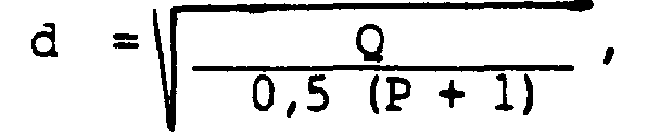
- the diameter of the capillary tube will preferably be equal to: d being expressed in millimeters, Q being the minimum oxygen flow rate according to the desired oxygen content of the fuel, expressed in Nm 3 / h, P the relative oxygen supply pressure expressed in bars, P being greater than 1 bar.
- the invention also relates to a method for the manufacture of glass objects in which the glass from a melting furnace flows to a machine for forming said objects, via a distribution channel, said channel comprising at least one burner device for heating and maintaining at a predetermined temperature the stream of molten glass flowing in said channel, said method being characterized in that at least one of the burner devices conforms to the device described above above, the oxygen flow rate coming from the oxygen supply means being such that the oxygen concentration by volume du of the oxidizer, after mixing the oxygen and the premix, under normal temperature and pressure conditions, remains substantially lower or equal to 30%.
- the control of the various burner devices is preferably carried out in the manner described below.
- the burner devices according to the invention are essentially intended to replace the burners existing in the feeders. They are supplied by a premixer connected to the air and combustible gas pipes, ensuring a constant ratio of the air and combustible gas flow rates. Control of the burners according to the invention by the same premixer, the setting of which would be changed for each variation of the oxygen flow rate (see below) would pose significant problems: This is in fact preset for a certain air / combustible gas ratio and it is therefore difficult to vary simultaneously, in commercially available premixers, the air and gas flow fuel in different proportions.
- the method according to the invention is characterized in that all of the burner devices are supplied with a premix of air and combustible gas in a predetermined ratio and according to a adjustable flow rate, while the burner devices are also supplied on the one hand with oxygen and on the other hand with combustible gas, added to the premix, whose respective flow rates are in said predetermined ratio.
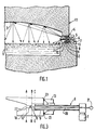
- FIG 1 there is shown a first variant of heating glass distribution channels according to US Patent 3,523,871.
- the distribution channel 2 in which the glass 1 flows is surmounted by a refractory vault 3.
- the air-gas burners used in the patent mentioned above respectively comprise a cylindrical pipe 6 connected at its upstream end to supply means 7 for premixing air and combustible gas, the downstream end 8 of which opens into a cylindrical bore 9 in a refractory block 10 inserted in the side wall 11 of the supply channel 2.
- the cylindrical bore 9 is extended by a cylindrical coaxial conduit 12 of diameter smaller than that of said bore 9.
- the cylindrical pipe 6 is capped by a sealing ring 13 which covers the face of the cylindrical bore 9 into which said pipe 6 penetrates.
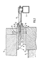
- Figure 2 is shown an alternative embodiment of Figure 1, in which a single burner is used, while the roof 3 is a flat roof.
- This variant is also an alternative embodiment of said American patent cited above.
- the same elements as those of the previous figure have the same references.
- the cylindrical pipe 6 comes substantially to the plane BB of separation of the bore 9 and the cylindrical coaxial conduit 12, the latter terminating at its other end along the plane AA.
- FIG. 3 represents the device according to the invention and intended to be substituted for devices 4 and / or 5 of the preceding figures.
- a capillary tube 20 is arranged coaxially with the pipe 6, inside the latter.
- the capillary tube is connected at its upstream end to oxygen supply means 21.
- This capillary tube opens at the downstream end 8 of the pipe 6, and extends as far as the cylindrical coaxial conduit 12.
- the downstream end of this capillary tube must not generally go beyond the plane AA in order to avoid its deterioration, clogging, etc. It must necessarily be located beyond the plane C-C representing the downstream end 8 of the pipe 6, in order to avoid the upwelling of oxygen in the premix and the risks of explosion which would result therefrom.
- this downstream end of the capillary tube will be situated in the zone where the speed of circulation of the premix is, in general, as high as possible, which, in the embodiment of FIG. 3, is represented by the zone of smaller diameter or cylindrical coaxial conduit 12, located between the planes AA and BB.
- the injection speed of the oxygen from the capillary is sonic so as to have the fastest possible mixture between the air-gas premix and the oxygen.
- the diameter of the capillary is given by the formula mentioned above, that is to say: Given the type of oxygen enrichment used and in order not to overheat the burner block, it was found that the volume concentration of oxygen in the fuel (air + oxygen), under normal conditions, should not exceed appreciably 30%.
- This example is carried out under the same conditions as above but with propane.
- Such a device also has the advantage, when a plurality of these are used in a supply channel, of being able to modulate the over-oxygenation of each and thus modulate the local overheating produced by the different burner devices, without variation in flow rate.
- the air-gas premix used for all burners This modulation is effected only from the oxygen supply manifold, the oxygen supply of each of the devices must of course in this case be separately adjustable (a flow valve adjustable by capillary tube).
- such a device and its implementation method make it possible to increase the temperature of the glass and preferably reheat the edges of the feeder.
- the over-oxygenation allows a moderate increase in the actual temperature of the flame, which results in a moderate increase in the temperature of the refractory block. This results in a significant increase in the radiation from the block to the banks of the channel which are heated by radiation from said block. (We know that this radiation is a function of the power 4 of its temperature.)
- FIG. 4 is an exemplary embodiment of a control system making it possible to modulate for each burner the rate of over-oxygenation.
- each zone 1, 2, ...; n of the feeder corresponds to a burner device according to the invention (but it is also possible to connect the system to conventional burners since the premix device 50 delivers on the pipe 70 a conventional air / combustible gas mixture).
- Each burner is connected by its lines 6 and 20 to a control module 101, 102, ..., lOn.
- Each module has an inlet 201, 202, ..., 20n for the pipe 70 for supplying air / fuel gas mixture from the premixer 50. Taking into account the fact that all the modules 101, 102, ..., 10n are identical, only the module 101 has been shown in detail and will be described below.
- the pipe 70 is connected to the controlled valve 51 for adjusting the flow, to the mixer 52 from which it comes out to be connected to the cylindrical pipe 6.
- the mixing device 52 receives via the pipe 54 and the controlled valve 53 with adjustable flow rate the combustible gas to be associated with the oxygen (as will be seen below). The latter is sent into the capillary tube 20 via the controlled valve 55 with adjustable flow rate and the pipe 71.
Landscapes
- Chemical & Material Sciences (AREA)
- Engineering & Computer Science (AREA)
- Materials Engineering (AREA)
- Organic Chemistry (AREA)
- Combustion & Propulsion (AREA)
- Physics & Mathematics (AREA)
- Thermal Sciences (AREA)
- Glass Melting And Manufacturing (AREA)
- Gas Burners (AREA)
Abstract
Description
- La présente invention concerne un dispositif pour améliorer le chauffage d'un canal de distribution du verre, ledit dispositif comportant une canalisation cylindrique reliée à son extrémité amont à des moyens d'alimentation en prémélange d'air et de gaz combustible et dont l'extrémité aval débouche à l'intérieur d'un alésage cylindrique dans un bloc réfractaire inséré dans une paroi du canal, ledit alésage cylindrique se prolongeant par un conduit axial cylindrique mais de diamètre inférieur à celui dudit alésage, la canalisation cylindrique étant coiffée par une bague d'étanchéité qui recouvre la face de l'alésage cylindrique dans lequel ladite canalisation pénètre.
- Une ligne de fabrication continue du verre comprend successivement un atelier de composition dans lequel on mélange les matières premières qui sont introduites dans le four de fusion, puis un avant bassin dans lequel le verre fondu passe en vue d'être soumis à un dégazage, puis un ou plusieurs canaux de distribution reliés à des machines de formage. Ces canaux de distribution ont deux fonctions, à savoir transporter le verre fondu et le conditionner en température.
- Le transport du verre fondu est assuré par gravité et l'écoulement de celui-ci se fait à faible vitesse de l'ordre de quelques mètres par heure.
- Le conditionnement en température du verre est la fonction la plus importante du canal de liaison (ou "feeder" selon l'appellation anglo-saxone) : c'est elle qui permet de fabriquer un produit de qualité élevée et régulière. Cette fonction de conditionnement se compose notamment de trois sous-fonctions :
- . Modification de la température du verre fondu : en général, refroidissement du verre de la température du four à la température de formage (dans certains cas réchauffement du verre).
- . Homogénéisation de la température du verre, afin de limiter les gradients transversaux et verticaux de température.
- . Régulation de la température du verre délivré aux machines de formage.
- La première sous-fonction peut être réalisée de deux manières différentes :
- 1) On refroidit violemment le verre pendant une courte durée puis on le laisse s'homogénéiser en température. Cette méthode nécessite des moyens de refroidissement internes (ventilation, circulation d'eau) qui réduisent le rendement effectif des équipements de chauffage installé pour maintenir un niveau de température suffisant dans le canal. De plus, cette technique demande une certaine connaissance des écoulement du verre dans le canal de façon à éviter les gradients transversaux de température trop importants.
- 2) On refroidit d'une façon continue et très lente le verre. Avec cette technique on a uniquement recours au refroidissement naturel dû aux pertes dans les parois du canal.
- Pour réaliser la deuxième sous-fonction (homogénéisation de la température du verre), il est nécessaire de réchauffer les zones marginales de la surface supérieure de la veine de verre, car les couches extérieures de cette veine se refroidissent beaucoup plus vite que le coeur, du fait que le verre est un bon isolant et que dans une masse de verre même chaud, les transferts de chaleur sont faibles. Les brûleurs utilisés pour réchauffer les zones marginales de la veine de verre sont généralement alimentés à partir d'une nourrice contenant un prémélange d'air froid et du gaz combustible utilisé, ce qui présente un certain danger en cas d'extinction de la flamme.
- Pour réaliser la troisième sous-fonction qui est rendue nécessaire pour obtenir une qualité constante du produit fini, le canal comporte plusieurs zones successives dont le chauffage est piloté globalement à partir d'une seule sonde de température.
- Dans un feeder destiné au verre en fusion, le verre s'écoule habituellement dans un canal réfractaire qui est isolé sur les côtés et à sa partie inférieure, en direction d'une cuvette d'alimentation placée à son extrémité aval. Pour les débits relativement faibles, de la chaleur est généralement fournie au moyen de brûleurs montés dans les parois latérales des feeders afin de chercher à maintenir le verre en fusion à la température désirée pour sa distribution dans la cuvette. Au débit d'écoulement plus élevé, de petites quantités de chaleur peuvent être appliquées de façon sélective, et une élimination de chaleur est nécessaire pour le débit accru comme cela est le cas dans les feeders actuellement construits.
- Pour réaliser des économies d'énergie en réduisant le ballast d'azote contenu dans le fumées dégagées par un brûleur et augmenter la température réelle de la flamme d'un brûleur, il est connu d'utiliser l'oxygène que l'on mélange au gaz combustible en plus ou moins grande quantité. Différentes méthodes bien connues peuvent être envisagées pour cette adjonction d'oxygène à un prémélange d'air et de gaz combustible :
- La dilution qui consiste à mélanger dans la canalisation d'amenée du mélange air-gaz combustible, l'oxygène supplémentaire. La multitude de brûleurs constituant une zone du feeder conduirait à des problèmes de sécurité si l'on introduisait de l'oxygène pur dans la nourrice de prémélange, ccnpte-tenu du déplacement des limites d'inflammabilité dudit mélange, de l'augmentation de la vitesse de déflagration en rapport avec une réduction de la vitesse de passage du mélange dans la nourrice et le brûleur. En effet, si l'on introduit un volume d'oxygène, il faut réduire la quantité d'air de cinq volumes, donc modifier le débit, c'est-à-dire la vitesse du mélange dans les canalisations. En pratique, cette solution n'est donc pas acceptable.
- Une seconde méthode consiste à utiliser une lance d'injection d'oxygène pur, c'est-à-dire amener par un tuyau séparé du brûleur de l'oxygène pur à proximité de la flamme du brûleur. Cette technique est particulièrement complexe, compte-tenu de la faible distance entre le brûleur et le bain de verre qui ne permet pas un implantation aisée desdites lances, de la faible largeur du canal d'alimentation nécessitant un mélange rapide de la flamme et de l'oxygène, du nombre important de trous à pratiquer dans la paroi latérale du feeder pour y installer les lances. Par conséquent, une telle solution nécessite d'inportantes modifications dans les installations existantes.
- Une troisième méthode consiste à utiliser des brûleurs oxycombustibles. L'utilisation de tels brûleurs nécessite cependant une conception nouvelle du feeder pour éviter la surchauffe des pièces réfractaires, ccnpte-tenu de la température très élevée à la base de la flamme des brûleurs oxycombustibles. Cette solution ne permet donc pas une adaptation aux canaux d'alimentation en verre tels qu'ils sont réalisés dans les installations en fonctionnement.
- Actuellement, se pose donc le problème de l'utilisation de l'oxygène dans les brûleurs air-gaz combustible placés dans les feeders, de manière à utiliser les installations existantes sans modification, tout en profitant des améliorations apportées par l'utilisation d'un comburant suroxygéné.
- L'invention permet de résoudre le problème ainsi posé. Le dispositif selon l'invention est caractérisé en ce qu'il comporte un tube capillaire disposé coaxialement à ladite canalisation et dont le diamètre est inférieur au diamètre de ladite canalisation, ledit tube capillaire étant relié à son extrémité amont à des moyens d'alimentation en oxygène et débouchant à l'extrémité aval de ladite canalisation entre l'extrémité du conduit coaxial cylindrique situé du côté dudit canal et l'extrémité aval de ladite canalisation.
- De préférence, ce dispositif dans lequel le diamètre du tube capillaire est inférieur à celui de conduit coaxial cylindrique, est caractérisé en ce que ledit tube capillaire débouche dans ledit conduit coaxial cylindrique.
- Le diamètre du tube capillaire sera de préférence égal à :

- L'invention concerne également un procédé pour la fabrication d'objets en verre dans lequel le verre issu d'un four de fusion s'écoule vers une machine pour le formage desdits objets, par l'intermédiaire d'un canal de distribution, ledit canal comportant au moins un dispositif brûleur pour chauffer et maintenir à une témpérature prédéterminée la veine de verre en fusion s'écoulant dans ledit canal, ledit procédé étant caractérisé en ce que l'un au moins des dispositifs brûleurs est conforme au dispositif décrit ci-dessus, le débit d'oxygène issu des moyens d'alimentation en oxygène étant tel que la concentration volumique Ψ en oxygène du comburant, après mélange de l'oxygène et du prémélange, dans les conditions normales de température et de pression, reste sensiblement inférieure ou égale à 30 %.
- Le pilotage des différents dispositifs brûleurs s'effectue, de préférence, de la manière décrite ci-après. Les dispositifs brûleurs selon l'invention sont essentiellement destinés à se substituer aux brûleurs existant dans les feeders. Ils sont alimentés par un prémélangeur connecté aux canalisations d'air et de gaz combustible, assurant un rapport constant des débits d'air et de gaz combustible. Le pilotage des brûleurs selon l'invention par le même prémélangeur dont on changerait le réglage pour chaque variation du débit d'oxygène (voir ci-après) poserait des problèmes importants : Celui-ci est en effet préréglé pour un certain rapport air/gaz combustible et il est difficile alors de faire varier simultanément, dans les prémélangeurs disponibles dans le commerce, le débit d'air et de gaz combustible dans des proportions différentes.
- Selon un mode préférentiel de réalisation, le procédé selon l'invention est caractérisé en ce que l'on alimente l'ensemble des dispositifs brûleurs à l'aide d'un prémélange d'air et de gaz combustible dans un rapport prédérerminé et selon un débit réglable, tandis que les dispositifs brûleurs sont également alimentés d'une part en oxygène et d'autre part en gaz combustible, additionné au prémélange, dont les débits respectifs sont dans ledit rapport prédéterminé.
- L'invention sera mieux comprise à l'aide des exemples de réalisation suivants, donnés à titre non limitatif, conjointement avec les figures qui représentent :
- - la figure 1, un exemple d'un canal de distribution de verre selon l'art antérieur, muni de brûleurs air-gaz ;
- - la figure 2, une variante de la figure 1, selon l'art antérieur ;
- - la figure 3, une vue en coupe schématique d'un dispositif selon l'invention adapté au chauffage des canaux de distribution de verre ;
- - la figure 4, un schéma de réalisation d'un système de pilotage d'un dispositif selon la figure 3.
- Sur la figure 1, est représentée une première variante de chauffage de canaux de distribution de verre selon le brevet américain 3.523.871. Le canal de distribution 2 dans lequel s'écoule le verre 1 est surmonté d'une voûte réfractaire 3. Dans la paroi latérale 11 de ce canal ou feeder, sont logés respectivement deux brûleurs 4 et 5 identiques, le brûleur 4 étant orienté de manière à chauffer la voûte 3, tandis que le brûleur 5 est orienté de manière à chauffer les bords latéraux du canal 2. les brûleurs air-gaz utilisés dans le brevet mentionné ci-dessus, comportent respectivement une canalisation cylindrique 6 reliée à son extrémité amont à des moyens d'alimentation 7 en prémélange d'air et de gaz combustible, et dont l'extrémité aval 8 débouche à l'intérieur d'un alésage cylindrique 9 dans un bloc réfractaire 10 inséré dans la paroi latérale 11 du canal d'alimentation 2. L'alésage cylindrique 9 se prolonge par un conduit coaxial cylindrique 12 de diamètre inférieur à celui dudit alésage 9. La canalisation cylindrique 6 est coiffée par une bague d'étanchéité 13 qui recouvre la face de l'alésage cylindrique 9 dans lequel ladite canalisation 6 pénètre.
- Sur la figure 2 est représentée une variante de réalisation de la figure 1, dans laquelle un seul brûleur est utilisé, tandis que la voûte 3 est une voûte plate. Cette variante est également une variante de réalisation dudit brevet américain cité plus haut. Sur cette figure, les mêmes éléments que ceux de la figure précédente portent les mêmes références. On notera en particulier le joint d'étanchéité 23 entre la bague d'étanchéité 13 et la paroi latérale où débouche la face de l'alésage cylindrique 9. Sur cette figure, la canalisation cylindrique 6 arrive sensiblement jusqu'au plan B-B de séparation de l'alésage 9 et du conduit coaxial cylindrique 12, celui-ci se terminant à son autre extrémité le long du plan A-A.
- La figure 3 représente le dispositif selon l'invention et destiné à être substitué aux dispositifs 4 et/ou 5 des figures précédentes. Sur cette figure 3, les mêmes éléments que ceux des figures précédentes portent les mêmes références. Un tube capillaire 20 est disposé coaxialement à la canalisation 6, à l'intérieur de celle-ci. Le tube capillaire est relié à son extrémité amont à des moyens d'alimentation en oxygène 21. Ce tube capillaire débouche à l'extrémité aval 8 de la canalisation 6, et se prolonge jusque dans le conduit coaxial cylindrique 12. L'extrémité aval de ce tube capillaire ne doit pas d'une manière générale aller au-delà du plan A-A afin d'éviter sa détérioration, son bouchage, etc. Il doit nécessairement se situer au-delà du plan C-C représentant l'extrémité aval 8 de la canalisation 6, afin d'éviter les remontées d'oxygène dans le prémélange et les risques d'explosion qui en résulteraient. De préférence, cette extrémité aval du tube capillaire sera située dans la zone eu la vitesse de circulation du prémélange est, d'une manière générale, la plus élevée possible ce qui, sur l'exemple de réalisation de la figure 3, est représenté par la zone de plus faible diamètre ou conduit coaxial cylindrique 12, située entre les plans A-A et B-B.
- Concernant les différents réglages à effectuer dans un canal d'alimentation de verre, on pourra éventuellement se reporter aux brevets français 2.022.539, 2.220.480 et 2.350.309, ainsi qu'au brevet américain sus-mentionné, dont les textes sont incorporés à la description de la présente demande à titre de référence.
- Les exemples ci-après permettent de montrer que la teneur en oxygène modifient considérablement le rendement de combustion des brûleurs selon l'invention :
- La vitesse d'injection de l'oxygène issu du capillaire est sonique de manière à avoir un mélange le plus rapide possible entre le prémélange air-gaz et l'oxygène. Le diamètre du capillaire est donné par la formule mentionnée plus haut, c'est-à-dire :
- On obtient, pour une température de fumées de 1200°C (valeur habituelle industriellement), un rendement qui passe de 40 % à 56,5 % du rendement de combustion d'un gaz naturel étalon, quand ψ passe de 20,8 % à 30 %. De même, avec un gaz propane disponible commercialement, le rendement passe de 44,2 % à 60 %.
- Si le débit initial de gaz naturel est QGNO = 1 associé à un débit d'air initial QAO, l'augmentation de rendement amènera une diminution de ce débit à QGN, d'où un débit d'air QA, un débit de prémélange QPM et un débit d'O2 pur QO2.
- On obtient (avec TF = 1200°C ; 2 % O2 dans les fumées sèches)

- Cet exemple est réalisé dans les mêmes conditions que précédemment mais avec du propane.

- Les exemples ci-dessus montrent donc que l'enrichissement en oxygène du dispositif selon l'invention permet de réduire la quantité de gaz consommé, c'est-à-dire réaliser des économies d'énergie, le prix de l'oxygène étant généralement inférieur à celui du gaz naturel ou du propane.
- Un tel dispositif présente de plus l'avantage lorsqu'une pluralité de ceux-ci sont utilisés dans un canal d'alimentation, de pouvoir moduler la suroxygénation de chacun et ainsi moduler la surchauffe locale réalisée par les différents dispositifs brûleur, sans variation de débit du prémélange air-gaz utilisé pour tous les brûleurs. Cette modulation s'effectue en effet uniquement à partir de la nourrice d'alimentation en oxygène, l'alimentation en oxygène de chacun des dispositifs devant bien entendu dans ce cas être modulable séparément (une vanne de débit réglable par tube capillaire). En outre, un tel dispositif et son procédé de mise en oeuvre permettent d'augmenter la température du verre et réchauffer préférentiellement les rives du feeder. De plus la suroxygénation permet une augmentation modérée de la température réelle de la flamme, ce qui se traduit par une augmentation modérée de la température du bloc réfractaire. Ceci se traduit par une augmentation sensible du rayonnement du bloc vers les rives du canal qui sont chauffées par rayonnement dudit bloc. (On sait que ce rayonnement est une fonction de la puissance 4 de sa température.)
- La figure 4 est un exemple de réalisation d'un système de pilotage permettant de moduler pour chaque brûleur le taux de suroxygénation. A chaque zone 1, 2, ...; n du feeder correspond un dispositif brûleur selon l'invention (mais on peut également prévoir de relier le système à des brûleurs conventionnels puisque le dispositif de prémélange 50 délivre sur la canalisation 70 un mélange air/gaz combustible conventionnel). Chaque brûleur est relié par ses canalisations 6 et 20 à un module de commande 101, 102, ..., lOn. Chaque module comporte une entrée 201, 202, ..., 20n pour la canalisation 70 d'amenée de mélange air/gaz combustible issu du prémélangeur 50. Compte tenu du fait que tous les modules 101, 102, ..., 10n sont identiques, seul le module 101 a été représenté en détails et va être décrit ci-après.
- La canalisation 70 est reliée à la vanne commandée 51 de réglage de débit, au mélangeur 52 dont elle sort pour être connectée à la canalisation cylindrique 6. Le dispositif mélangeur 52, bien connu de l'homme de métier, reçoit par la canalisation 54 et la vanne commandée 53 à débit réglable le gaz combustible à associer à l'oxygène (ainsi qu'on le verra plus loin). Ce dernier est envoyé dans le tube capillaire 20 par l'intermédiaire de la vanne commandée 55 à débit réglable et la canalisation 71.
- La vanne commandée 51 est reliée électriquement par la connexion 60 à un dispositif électronique d'asservissement de débit 57, lui-même relié via 61 à l'opérateur de rapport 56, ce dernier étant relié électriquement aux vannes commandées 53 et 55 respectivement via les connexions 58 et 59. Lors d'une variation de position de la vanne 51, commandée manuellement ou électriquement, le dispositif d'asservissement 57 permet de faire varier proportionnellement le signal de commande envoyé vers l'opérateur de rapport 56. Celui-ci engendre le signal de variation de débit de chaque vanne 53 et 55 en maintenant le rapport (en général stoechiométrique) entre le gaz combustible et l'oxygène. Inversement, on règle le taux de suroxygénation en modifiant la proportion du dispositif d'asservissement 57. L'opérateur de rapport 56 ajuste automatiquement les débits des vannes 53 et 55 en maintenant la stoechiométrie, tandis que le dispositif 57 ajuste la puissance oxyccmbustible aux variations de la puissance aérocombustible commandées par la vanne 51. Un tel système de pilotage présente notamment les avantages suivants :
- - aucun déréglage du prémélangeur n'est nécessaire : celui-ci fonctionne dans les conditions prévues par le constructeur,
- - chaque zone peut correspondre à une suroxygénation différente et donc à une température différente. Pour cela, il suffit de choisir une proportion différente au niveau de 57, en fonction de la température voulue pour la zone correspondante. (En version manuelle, on change le débit global des vannes 53 et 55, en maintenant le même rapport).
- En fonction de ce qui vient d'être décrit et en maintenant un rapport stoechiométrique oxygène (air)/gaz naturel, les tableaux des exemples 1 et 2 sont modifiés comme suit :
- (Mêmes conditions que l'exerple 1)

- (Mêmes conditions que l'exemple 2)

Claims (8)

Priority Applications (1)
| Application Number | Priority Date | Filing Date | Title |
|---|---|---|---|
| AT86402013T ATE36307T1 (de) | 1985-09-20 | 1986-09-15 | Vorrichtung zur verbesserung der heizung in einem glasverteilungskanal und verfahren zur verwendung dieser vorrichtung. |
Applications Claiming Priority (2)
| Application Number | Priority Date | Filing Date | Title |
|---|---|---|---|
| FR8513949A FR2587695B1 (fr) | 1985-09-20 | 1985-09-20 | Dispositif pour ameliorer le chauffage d'un canal de distribution de verre et procede pour la mise en oeuvre d'un tel dispositif |
| FR8513949 | 1985-09-20 |
Publications (2)
| Publication Number | Publication Date |
|---|---|
| EP0216698A1 true EP0216698A1 (fr) | 1987-04-01 |
| EP0216698B1 EP0216698B1 (fr) | 1988-08-10 |
Family
ID=9323089
Family Applications (1)
| Application Number | Title | Priority Date | Filing Date |
|---|---|---|---|
| EP86402013A Expired EP0216698B1 (fr) | 1985-09-20 | 1986-09-15 | Dispositif pour améliorer le chauffage d'un canal de distribution de verre et procédé pour la mise en oeuvre d'un tel dispositif |
Country Status (15)
| Country | Link |
|---|---|
| US (1) | US4708728A (fr) |
| EP (1) | EP0216698B1 (fr) |
| JP (1) | JP2529950B2 (fr) |
| KR (1) | KR870003018A (fr) |
| AR (1) | AR240892A1 (fr) |
| AT (1) | ATE36307T1 (fr) |
| AU (1) | AU575535B2 (fr) |
| BR (1) | BR8604479A (fr) |
| CA (1) | CA1309592C (fr) |
| DE (1) | DE3660485D1 (fr) |
| DK (1) | DK165058C (fr) |
| ES (1) | ES2000898A6 (fr) |
| FR (1) | FR2587695B1 (fr) |
| PT (1) | PT83396B (fr) |
| ZA (1) | ZA867014B (fr) |
Cited By (5)
| Publication number | Priority date | Publication date | Assignee | Title |
|---|---|---|---|---|
| EP0633228A3 (fr) * | 1993-07-06 | 1995-10-18 | Corning Inc | Canal de distribution de verre à chauffage oxy/fuel, procédé et brûleur oxy/fuel. |
| FR2735122A1 (fr) * | 1995-06-08 | 1996-12-13 | Saint Gobain Emballage | Dispositif de combustion |
| EP0893414A1 (fr) * | 1997-07-14 | 1999-01-27 | Ernst Vieler | Procédé de réglage de la dose d'oxygène dans un canal de distribution de verre pendant la fabrication de verre |
| EP2063176A1 (fr) | 2007-11-22 | 2009-05-27 | L'Air Liquide Société Anonyme pour l'Etude et l'Exploitation des Procédés Georges Claude | Oxybrûleur |
| EP2392857A1 (fr) | 2010-06-07 | 2011-12-07 | L'Air Liquide Société Anonyme pour l'Etude et l'Exploitation des Procédés Georges Claude | Brûleur d'oxycarburants |
Families Citing this family (14)
| Publication number | Priority date | Publication date | Assignee | Title |
|---|---|---|---|---|
| DE4222863C2 (de) * | 1992-07-11 | 1995-07-06 | Sorg Gmbh & Co Kg | Brenner für eine regenerative Schmelzwanne mit einem Brennerhals |
| US5346524A (en) * | 1992-09-14 | 1994-09-13 | Schuller International, Inc. | Oxygen/fuel firing of furnaces with massive, low velocity, turbulent flames |
| US5643348A (en) * | 1992-09-14 | 1997-07-01 | Schuller International, Inc. | Oxygen/fuel fired furnaces having massive, low velocity, turbulent flame clouds |
| US5500030A (en) * | 1994-03-03 | 1996-03-19 | Combustion Tec, Inc. | Oxy-gas fired forehearth burner system |
| US5814121A (en) * | 1996-02-08 | 1998-09-29 | The Boc Group, Inc. | Oxygen-gas fuel burner and glass forehearth containing the oxygen-gas fuel burner |
| US6237369B1 (en) | 1997-12-17 | 2001-05-29 | Owens Corning Fiberglas Technology, Inc. | Roof-mounted oxygen-fuel burner for a glass melting furnace and process of using the oxygen-fuel burner |
| US6029910A (en) * | 1998-02-05 | 2000-02-29 | American Air Liquide, Inc. | Low firing rate oxy-fuel burner |
| KR20000020505A (ko) * | 1998-09-22 | 2000-04-15 | 박영구 | 유리용해로의 산소공급 제어장치 |
| KR20000050536A (ko) * | 1999-01-11 | 2000-08-05 | 서두칠 | 유리용융로 |
| KR100438413B1 (ko) * | 1999-01-11 | 2004-07-02 | 한국전기초자 주식회사 | 유리용융로 |
| US6233974B1 (en) | 1999-01-25 | 2001-05-22 | Combustion Tec | Oxygen-gaseous forehearth burner for air-fuel and oxy-fuel forehearth burner block geometries |
| EP1889816A1 (fr) * | 2006-08-15 | 2008-02-20 | Rockwool International A/S | Procédé et dispositif pour la fabrication de fibres minérales |
| FR2924201B1 (fr) * | 2007-11-23 | 2013-08-16 | Air Liquide | Procede de chauffage au moyen d'un oxybruleur comportant un injecteur dispose a l'interieur d'un bloc |
| GB201418727D0 (en) * | 2014-10-21 | 2014-12-03 | Five Stein Ltd | Forehearths and burner blocks for use therein |
Citations (2)
| Publication number | Priority date | Publication date | Assignee | Title |
|---|---|---|---|---|
| FR1450020A (fr) * | 1965-10-04 | 1966-05-06 | Australian Gas Light Company | Perfectionnements au chauffage des connexions de feeders utilisées dans l'industrie du verre pour alimenter des machines à mouler |
| FR1479461A (fr) * | 1966-03-22 | 1967-05-05 | Saint Gobain | Perfectionnements aux canaux amenant le verre fondu à des postes de travail |
Family Cites Families (7)
| Publication number | Priority date | Publication date | Assignee | Title |
|---|---|---|---|---|
| US2499207A (en) * | 1945-12-22 | 1950-02-28 | John J Wolfersperger | Pressure-type burner and method of burning fuel |
| US3321288A (en) * | 1964-02-28 | 1967-05-23 | Owens Corning Fiberglass Corp | Method for controlling the temperature of heat-softenable material |
| DE1903595A1 (de) * | 1968-01-25 | 1969-10-09 | Daido Sanso Kabushiki Kaisha O | Verfahren und Vorrichtung zum fortlaufenden Erzeugen einer Flamme von hoher Temperatur |
| US3954433A (en) * | 1974-08-22 | 1976-05-04 | Owens-Corning Fiberglas Corporation | Method of and apparatus for coordinating the application of heat to a melt from sources above and below the melt surface |
| SU643717A1 (ru) * | 1977-01-10 | 1979-01-25 | Всесоюзный научно-исследовательский институт природных газов | Способ реформировани жидкого топлива |
| FR2546155B1 (fr) * | 1983-05-20 | 1986-06-27 | Air Liquide | Procede et installation d'elaboration de verre |
| FR2567118B1 (fr) * | 1984-07-04 | 1986-11-14 | Air Liquide | Procede de chauffage d'un canal contenant du verre a l'aide de flammes oxy-combustibles |
-
1985
- 1985-09-20 FR FR8513949A patent/FR2587695B1/fr not_active Expired
-
1986
- 1986-09-15 AT AT86402013T patent/ATE36307T1/de not_active IP Right Cessation
- 1986-09-15 ZA ZA867014A patent/ZA867014B/xx unknown
- 1986-09-15 DE DE8686402013T patent/DE3660485D1/de not_active Expired
- 1986-09-15 EP EP86402013A patent/EP0216698B1/fr not_active Expired
- 1986-09-16 ES ES8601921A patent/ES2000898A6/es not_active Expired
- 1986-09-16 US US06/908,351 patent/US4708728A/en not_active Expired - Lifetime
- 1986-09-17 AU AU62981/86A patent/AU575535B2/en not_active Ceased
- 1986-09-17 DK DK445186A patent/DK165058C/da not_active IP Right Cessation
- 1986-09-18 PT PT83396A patent/PT83396B/pt not_active IP Right Cessation
- 1986-09-18 BR BR8604479A patent/BR8604479A/pt not_active IP Right Cessation
- 1986-09-19 JP JP61219867A patent/JP2529950B2/ja not_active Expired - Lifetime
- 1986-09-19 CA CA000518658A patent/CA1309592C/fr not_active Expired - Lifetime
- 1986-09-19 AR AR305308A patent/AR240892A1/es active
- 1986-09-20 KR KR1019860007892A patent/KR870003018A/ko not_active Withdrawn
Patent Citations (2)
| Publication number | Priority date | Publication date | Assignee | Title |
|---|---|---|---|---|
| FR1450020A (fr) * | 1965-10-04 | 1966-05-06 | Australian Gas Light Company | Perfectionnements au chauffage des connexions de feeders utilisées dans l'industrie du verre pour alimenter des machines à mouler |
| FR1479461A (fr) * | 1966-03-22 | 1967-05-05 | Saint Gobain | Perfectionnements aux canaux amenant le verre fondu à des postes de travail |
Cited By (8)
| Publication number | Priority date | Publication date | Assignee | Title |
|---|---|---|---|---|
| EP0633228A3 (fr) * | 1993-07-06 | 1995-10-18 | Corning Inc | Canal de distribution de verre à chauffage oxy/fuel, procédé et brûleur oxy/fuel. |
| US5560758A (en) * | 1993-07-06 | 1996-10-01 | Corning Incorporated | Method for making glass articles |
| FR2735122A1 (fr) * | 1995-06-08 | 1996-12-13 | Saint Gobain Emballage | Dispositif de combustion |
| EP0893414A1 (fr) * | 1997-07-14 | 1999-01-27 | Ernst Vieler | Procédé de réglage de la dose d'oxygène dans un canal de distribution de verre pendant la fabrication de verre |
| EP2063176A1 (fr) | 2007-11-22 | 2009-05-27 | L'Air Liquide Société Anonyme pour l'Etude et l'Exploitation des Procédés Georges Claude | Oxybrûleur |
| EP2063175A1 (fr) * | 2007-11-22 | 2009-05-27 | L'AIR LIQUIDE, Société Anonyme pour l'Etude et l'Exploitation des Procédés Georges Claude | Oxybrûleur |
| EP2392857A1 (fr) | 2010-06-07 | 2011-12-07 | L'Air Liquide Société Anonyme pour l'Etude et l'Exploitation des Procédés Georges Claude | Brûleur d'oxycarburants |
| WO2011154285A1 (fr) | 2010-06-07 | 2011-12-15 | L'air Liquide, Societe Anonyme Pour L'etude Et L'exploitation Des Procedes Georges Claude | Brûleur oxygaz |
Also Published As
| Publication number | Publication date |
|---|---|
| DK165058C (da) | 1993-02-22 |
| DK445186D0 (da) | 1986-09-17 |
| DE3660485D1 (en) | 1988-09-15 |
| AR240892A1 (es) | 1991-03-27 |
| US4708728A (en) | 1987-11-24 |
| FR2587695A1 (fr) | 1987-03-27 |
| DK165058B (da) | 1992-10-05 |
| FR2587695B1 (fr) | 1987-11-20 |
| AU575535B2 (en) | 1988-07-28 |
| ATE36307T1 (de) | 1988-08-15 |
| PT83396A (fr) | 1986-10-01 |
| CA1309592C (fr) | 1992-11-03 |
| PT83396B (pt) | 1992-10-30 |
| BR8604479A (pt) | 1987-05-19 |
| JPS6269010A (ja) | 1987-03-30 |
| KR870003018A (ko) | 1987-04-14 |
| AU6298186A (en) | 1987-03-26 |
| AR240892A2 (es) | 1991-03-27 |
| ES2000898A6 (es) | 1988-03-16 |
| ZA867014B (en) | 1987-04-29 |
| DK445186A (da) | 1987-03-21 |
| EP0216698B1 (fr) | 1988-08-10 |
| JP2529950B2 (ja) | 1996-09-04 |
Similar Documents
| Publication | Publication Date | Title |
|---|---|---|
| EP0216698B1 (fr) | Dispositif pour améliorer le chauffage d'un canal de distribution de verre et procédé pour la mise en oeuvre d'un tel dispositif | |
| EP2731918B1 (fr) | Installation et procede de fusion de verre | |
| CA1253745A (fr) | Bruleur a charbon pulverise | |
| US9568194B2 (en) | Burner assembly and method of combustion | |
| EP0643262B1 (fr) | Procédé de combustion | |
| CA2995669A1 (fr) | Bruleur d'oxycarburant a double etage | |
| EP1379810A1 (fr) | Procede de combustion comportant des injections separees de combustible et d'oxydant et ensemble bruleur pour la mise en oeuvre de ce procede | |
| FR2462658A1 (fr) | Procede et appareil pour le sechage et le broyage fin du charbon, pour l'alimentation d'un foyer a poussier de charbon | |
| EP0481835B1 (fr) | Procédé de chauffe d'une enceinte thermique et brûleur | |
| EP1704366B1 (fr) | Procede de combustion etagee mettant en oeuvre un gaz pauvre en oxygene | |
| EP1702177A1 (fr) | Procede de combustion etagee avec injection optimisee de l'oxydant primaire | |
| FR2757844A1 (fr) | Procede de fabrication de verre technique et bruleur pour la mise en oeuvre d'un tel procede | |
| EP2546204A1 (fr) | Procédé et installation de fusion de verre | |
| EP3715717B1 (fr) | Procédé de combustion et brûleur pour sa mise en oeuvre | |
| EP0807608B1 (fr) | Procédé pour la réparation d'un four de verre à l'aide d'un brûleur auxiliaire à combustion d'oxygène | |
| EP0597761A1 (fr) | Décharge et procédé de vitrification de déchets | |
| CA2704800A1 (fr) | Procede et systeme de combustion | |
| FR2484610A1 (fr) | Procede pour l'obtention d'un melange de gaz et d'air et four a gaz pour la mise en oeuvre du procede | |
| EP0922668B9 (fr) | Dispositif pour la fabrication de bromure d'hydrogène | |
| EP1625098B1 (fr) | Procédé de contrôle de brûleurs oxy-combustible par injection d'un gaz additionnel | |
| EP0493994A1 (fr) | Dispositif d'allumage d'un lit de mélange de matériaux tels que du minerai et du coke | |
| BE697455A (fr) | ||
| EP2141129A1 (fr) | Ensemble brûleur à flexibilité renforcée | |
| EP0011564A1 (fr) | Procédé et dispositif pour le réglage de la fabrication de fibres en matière thermoplastique | |
| BE821191A (fr) | Bruleur a impulsion et installation equipee d'un tel bruleur |
Legal Events
| Date | Code | Title | Description |
|---|---|---|---|
| PUAI | Public reference made under article 153(3) epc to a published international application that has entered the european phase |
Free format text: ORIGINAL CODE: 0009012 |
|
| 17P | Request for examination filed |
Effective date: 19860918 |
|
| AK | Designated contracting states |
Kind code of ref document: A1 Designated state(s): AT BE CH DE FR GB IT LI LU NL SE |
|
| 17Q | First examination report despatched |
Effective date: 19880126 |
|
| ITF | It: translation for a ep patent filed | ||
| GRAA | (expected) grant |
Free format text: ORIGINAL CODE: 0009210 |
|
| AK | Designated contracting states |
Kind code of ref document: B1 Designated state(s): AT BE CH DE FR GB IT LI LU NL SE |
|
| PG25 | Lapsed in a contracting state [announced via postgrant information from national office to epo] |
Ref country code: GB Free format text: LAPSE BECAUSE OF NON-PAYMENT OF DUE FEES Effective date: 19880810 |
|
| REF | Corresponds to: |
Ref document number: 36307 Country of ref document: AT Date of ref document: 19880815 Kind code of ref document: T |
|
| REF | Corresponds to: |
Ref document number: 3660485 Country of ref document: DE Date of ref document: 19880915 |
|
| GBV | Gb: ep patent (uk) treated as always having been void in accordance with gb section 77(7)/1977 [no translation filed] | ||
| PLBE | No opposition filed within time limit |
Free format text: ORIGINAL CODE: 0009261 |
|
| STAA | Information on the status of an ep patent application or granted ep patent |
Free format text: STATUS: NO OPPOSITION FILED WITHIN TIME LIMIT |
|
| 26N | No opposition filed | ||
| ITTA | It: last paid annual fee | ||
| EPTA | Lu: last paid annual fee | ||
| PGFP | Annual fee paid to national office [announced via postgrant information from national office to epo] |
Ref country code: LU Payment date: 19940801 Year of fee payment: 9 |
|
| PGFP | Annual fee paid to national office [announced via postgrant information from national office to epo] |
Ref country code: CH Payment date: 19940812 Year of fee payment: 9 Ref country code: AT Payment date: 19940812 Year of fee payment: 9 |
|
| PGFP | Annual fee paid to national office [announced via postgrant information from national office to epo] |
Ref country code: SE Payment date: 19940815 Year of fee payment: 9 |
|
| EAL | Se: european patent in force in sweden |
Ref document number: 86402013.6 |
|
| PG25 | Lapsed in a contracting state [announced via postgrant information from national office to epo] |
Ref country code: LU Free format text: LAPSE BECAUSE OF NON-PAYMENT OF DUE FEES Effective date: 19950915 Ref country code: AT Effective date: 19950915 |
|
| PG25 | Lapsed in a contracting state [announced via postgrant information from national office to epo] |
Ref country code: SE Effective date: 19950916 |
|
| PG25 | Lapsed in a contracting state [announced via postgrant information from national office to epo] |
Ref country code: LI Effective date: 19950930 Ref country code: CH Effective date: 19950930 |
|
| REG | Reference to a national code |
Ref country code: CH Ref legal event code: PL |
|
| EUG | Se: european patent has lapsed |
Ref document number: 86402013.6 |
|
| PGFP | Annual fee paid to national office [announced via postgrant information from national office to epo] |
Ref country code: FR Payment date: 20000807 Year of fee payment: 15 |
|
| PGFP | Annual fee paid to national office [announced via postgrant information from national office to epo] |
Ref country code: NL Payment date: 20000814 Year of fee payment: 15 |
|
| PGFP | Annual fee paid to national office [announced via postgrant information from national office to epo] |
Ref country code: DE Payment date: 20000823 Year of fee payment: 15 |
|
| PGFP | Annual fee paid to national office [announced via postgrant information from national office to epo] |
Ref country code: BE Payment date: 20000908 Year of fee payment: 15 |
|
| PG25 | Lapsed in a contracting state [announced via postgrant information from national office to epo] |
Ref country code: BE Free format text: LAPSE BECAUSE OF NON-PAYMENT OF DUE FEES Effective date: 20010930 |
|
| BERE | Be: lapsed |
Owner name: L' AIR LIQUIDE S.A. POUR L'ETUDE ET L'EXPLOITATION Effective date: 20010930 |
|
| PG25 | Lapsed in a contracting state [announced via postgrant information from national office to epo] |
Ref country code: NL Free format text: LAPSE BECAUSE OF NON-PAYMENT OF DUE FEES Effective date: 20020401 |
|
| PG25 | Lapsed in a contracting state [announced via postgrant information from national office to epo] |
Ref country code: DE Free format text: LAPSE BECAUSE OF NON-PAYMENT OF DUE FEES Effective date: 20020501 |
|
| PG25 | Lapsed in a contracting state [announced via postgrant information from national office to epo] |
Ref country code: FR Free format text: LAPSE BECAUSE OF NON-PAYMENT OF DUE FEES Effective date: 20020531 |
|
| NLV4 | Nl: lapsed or anulled due to non-payment of the annual fee |
Effective date: 20020401 |
|
| REG | Reference to a national code |
Ref country code: FR Ref legal event code: ST |
|
| NLV4 | Nl: lapsed or anulled due to non-payment of the annual fee |
Effective date: 20020401 |
|
| PG25 | Lapsed in a contracting state [announced via postgrant information from national office to epo] |
Ref country code: IT Free format text: LAPSE BECAUSE OF NON-PAYMENT OF DUE FEES Effective date: 20050915 |