EP0216698B1 - Vorrichtung zur Verbesserung der Heizung in einem Glasverteilungskanal und Verfahren zur Verwendung dieser Vorrichtung - Google Patents
Vorrichtung zur Verbesserung der Heizung in einem Glasverteilungskanal und Verfahren zur Verwendung dieser Vorrichtung Download PDFInfo
- Publication number
- EP0216698B1 EP0216698B1 EP86402013A EP86402013A EP0216698B1 EP 0216698 B1 EP0216698 B1 EP 0216698B1 EP 86402013 A EP86402013 A EP 86402013A EP 86402013 A EP86402013 A EP 86402013A EP 0216698 B1 EP0216698 B1 EP 0216698B1
- Authority
- EP
- European Patent Office
- Prior art keywords
- oxygen
- duct
- fuel gas
- burner
- flow rate
- Prior art date
- Legal status (The legal status is an assumption and is not a legal conclusion. Google has not performed a legal analysis and makes no representation as to the accuracy of the status listed.)
- Expired
Links
- 239000011521 glass Substances 0.000 title claims description 30
- 238000000034 method Methods 0.000 title claims description 17
- 238000010438 heat treatment Methods 0.000 title claims description 9
- QVGXLLKOCUKJST-UHFFFAOYSA-N atomic oxygen Chemical compound [O] QVGXLLKOCUKJST-UHFFFAOYSA-N 0.000 claims description 43
- 239000001301 oxygen Substances 0.000 claims description 43
- 229910052760 oxygen Inorganic materials 0.000 claims description 43
- 239000002737 fuel gas Substances 0.000 claims description 14
- 239000000203 mixture Substances 0.000 claims description 13
- 239000006060 molten glass Substances 0.000 claims description 8
- 238000011144 upstream manufacturing Methods 0.000 claims description 6
- 238000002156 mixing Methods 0.000 claims description 5
- 238000004519 manufacturing process Methods 0.000 claims description 4
- 238000007789 sealing Methods 0.000 claims description 4
- 210000003462 vein Anatomy 0.000 claims description 4
- 238000002844 melting Methods 0.000 claims description 3
- 230000008018 melting Effects 0.000 claims description 3
- 239000007789 gas Substances 0.000 description 20
- 241001639412 Verres Species 0.000 description 10
- VNWKTOKETHGBQD-UHFFFAOYSA-N methane Chemical compound C VNWKTOKETHGBQD-UHFFFAOYSA-N 0.000 description 8
- ATUOYWHBWRKTHZ-UHFFFAOYSA-N Propane Chemical compound CCC ATUOYWHBWRKTHZ-UHFFFAOYSA-N 0.000 description 6
- 238000006213 oxygenation reaction Methods 0.000 description 5
- 239000000446 fuel Substances 0.000 description 4
- 238000009434 installation Methods 0.000 description 4
- 239000003345 natural gas Substances 0.000 description 4
- 239000007800 oxidant agent Substances 0.000 description 4
- MYMOFIZGZYHOMD-UHFFFAOYSA-N Dioxygen Chemical compound O=O MYMOFIZGZYHOMD-UHFFFAOYSA-N 0.000 description 3
- 230000008901 benefit Effects 0.000 description 3
- 230000003750 conditioning effect Effects 0.000 description 3
- 238000001816 cooling Methods 0.000 description 3
- 230000004048 modification Effects 0.000 description 3
- 238000012986 modification Methods 0.000 description 3
- 239000001294 propane Substances 0.000 description 3
- 230000005855 radiation Effects 0.000 description 3
- 239000000243 solution Substances 0.000 description 3
- IJGRMHOSHXDMSA-UHFFFAOYSA-N Atomic nitrogen Chemical compound N#N IJGRMHOSHXDMSA-UHFFFAOYSA-N 0.000 description 2
- 238000002485 combustion reaction Methods 0.000 description 2
- 238000000265 homogenisation Methods 0.000 description 2
- 238000013021 overheating Methods 0.000 description 2
- 230000001590 oxidative effect Effects 0.000 description 2
- 230000009467 reduction Effects 0.000 description 2
- 238000009423 ventilation Methods 0.000 description 2
- 230000006978 adaptation Effects 0.000 description 1
- 230000008033 biological extinction Effects 0.000 description 1
- 230000008859 change Effects 0.000 description 1
- 238000004200 deflagration Methods 0.000 description 1
- 238000007872 degassing Methods 0.000 description 1
- 238000013461 design Methods 0.000 description 1
- 230000006866 deterioration Effects 0.000 description 1
- 238000010790 dilution Methods 0.000 description 1
- 239000012895 dilution Substances 0.000 description 1
- 238000006073 displacement reaction Methods 0.000 description 1
- 238000004880 explosion Methods 0.000 description 1
- 239000003517 fume Substances 0.000 description 1
- 230000005484 gravity Effects 0.000 description 1
- 238000002347 injection Methods 0.000 description 1
- 239000007924 injection Substances 0.000 description 1
- 239000012212 insulator Substances 0.000 description 1
- 229910052757 nitrogen Inorganic materials 0.000 description 1
- 239000002994 raw material Substances 0.000 description 1
- 239000000523 sample Substances 0.000 description 1
- 238000000926 separation method Methods 0.000 description 1
- 239000000779 smoke Substances 0.000 description 1
- XLYOFNOQVPJJNP-UHFFFAOYSA-N water Substances O XLYOFNOQVPJJNP-UHFFFAOYSA-N 0.000 description 1
Images


Classifications
-
- C—CHEMISTRY; METALLURGY
- C03—GLASS; MINERAL OR SLAG WOOL
- C03B—MANUFACTURE, SHAPING, OR SUPPLEMENTARY PROCESSES
- C03B5/00—Melting in furnaces; Furnaces so far as specially adapted for glass manufacture
- C03B5/16—Special features of the melting process; Auxiliary means specially adapted for glass-melting furnaces
-
- C—CHEMISTRY; METALLURGY
- C03—GLASS; MINERAL OR SLAG WOOL
- C03B—MANUFACTURE, SHAPING, OR SUPPLEMENTARY PROCESSES
- C03B7/00—Distributors for the molten glass; Means for taking-off charges of molten glass; Producing the gob, e.g. controlling the gob shape, weight or delivery tact
- C03B7/02—Forehearths, i.e. feeder channels
- C03B7/06—Means for thermal conditioning or controlling the temperature of the glass
- C03B7/065—Means for thermal conditioning or controlling the temperature of the glass by combustion with pure oxygen or oxygen-enriched air
-
- Y—GENERAL TAGGING OF NEW TECHNOLOGICAL DEVELOPMENTS; GENERAL TAGGING OF CROSS-SECTIONAL TECHNOLOGIES SPANNING OVER SEVERAL SECTIONS OF THE IPC; TECHNICAL SUBJECTS COVERED BY FORMER USPC CROSS-REFERENCE ART COLLECTIONS [XRACs] AND DIGESTS
- Y02—TECHNOLOGIES OR APPLICATIONS FOR MITIGATION OR ADAPTATION AGAINST CLIMATE CHANGE
- Y02P—CLIMATE CHANGE MITIGATION TECHNOLOGIES IN THE PRODUCTION OR PROCESSING OF GOODS
- Y02P40/00—Technologies relating to the processing of minerals
- Y02P40/50—Glass production, e.g. reusing waste heat during processing or shaping
- Y02P40/57—Improving the yield, e-g- reduction of reject rates
Definitions
- the present invention relates to a device for improving the heating of a glass distribution channel, said device comprising a cylindrical pipe connected at its upstream end to means for supplying premixture of air and combustible gas and the end of which downstream opens into a cylindrical bore in a refractory block inserted in a wall of the channel, said cylindrical bore extending by a cylindrical axial duct but of diameter less than that of said bore, the cylindrical pipe being capped by a ring of sealing which covers the face of the cylindrical bore into which said pipe penetrates.
- a continuous glass production line successively comprises a composition workshop in which the raw materials which are introduced into the melting furnace are mixed, then a front basin in which the molten glass passes in order to be subjected to degassing, then one or more distribution channels connected to forming machines. These distribution channels have two functions, namely transporting the molten glass and conditioning it in temperature.
- the molten glass is transported by gravity and the flow takes place at low speed of the order of a few meters per hour.
- the burners used to heat the marginal areas of the glass vein are generally supplied from a manifold containing a premix of cold air and the combustible gas used, which presents a certain danger in the event of extinction of the flame.
- the channel comprises several successive zones, the heating of which is controlled overall from a single temperature probe.
- the glass In a feeder intended for molten glass, the glass usually flows through a refractory channel which is insulated on the sides and at its lower part, in the direction of a feeding bowl placed at its downstream end.
- heat is generally supplied by means of burners mounted in the side walls of the feeders in order to seek to keep the molten glass at the desired temperature for its distribution in the bowl.
- small amounts of heat can be selectively applied, and heat removal is required for the increased flow rate as is the case in currently constructed feeders.
- the dilution which consists in mixing in the supply pipe of the air-combustible gas mixture, the additional oxygen.
- the multitude of burners constituting a feeder zone would lead to safety problems if pure oxygen were introduced into the premix tank, taking into account the displacement of the flammability limits of said mixture, the increase in the deflagration speed in connection with a reduction in the speed of passage of the mixture through the manifold and the burner. Indeed, if one introduces a volume of oxygen, it is necessary to reduce the quantity of air by five volumes, therefore to modify the flow rate, that is to say the speed of the mixture in the pipes. In practice, this solution is therefore not acceptable.
- a second method consists in using a lance for injecting pure oxygen, that is to say bringing by a pipe separate from the burner pure oxygen near the flame of the burner.
- This technique is particularly complex, given the short distance between the burner and the glass bath which does not allow easy installation of said lances, the small width of the supply channel requiring mixing. rapid flame and oxygen, the large number of holes to be made in the side wall of the feeder to install the lances. Consequently, such a solution requires significant modifications to existing installations.
- a third method is to use oxy-fuel burners.
- the use of such burners requires a new design of the feeder to avoid overheating of the refractory parts. taking into account the very high temperature at the base of the flame of the oxy-fuel burners. This solution therefore does not allow adaptation to the glass supply channels as they are produced in operating installations.
- the invention solves the problem thus posed.
- the device according to the invention is characterized in that it comprises a capillary tube disposed coaxially with said pipe and the diameter of which is less than the diameter of said pipe, said capillary tube being connected at its upstream end to means for supplying oxygen and opening at the downstream end of said pipe between the end of the cylindrical coaxial duct situated on the side of said channel and the downstream end of said pipe.
- this device in which the diameter of the capillary tube is less than that of the cylindrical coaxial conduit, is characterized in that the said capillary tube opens into the said cylindrical coaxial conduit.
- the diameter of the capillary tube will preferably be equal to: d being expressed in millimeters, Q being the minimum oxygen flow rate according to the desired oxygen content of the oxidant, expressed in Nm 3 / h, P the relative oxygen supply pressure expressed in bars, P being greater than 1 bar.
- the invention also relates to a method for manufacturing glass objects in which the glass from a melting furnace flows to a machine for forming said objects, via a distribution channel, said channel comprising at least one burner device for heating and maintaining at a predetermined temperature the stream of molten glass flowing in said channel, said method being characterized in that at least one of the burner devices conforms to the device described above above, the oxygen flow rate coming from the oxygen supply means being such that the oxygen concentration by volume du of the oxidizer, after mixing the oxygen and the premix, under normal temperature and pressure conditions, remains substantially lower or equal to 30%.
- the control of the various burner devices is preferably carried out in the manner described below.
- the burner devices according to the invention are essentially intended to replace the burners existing in the feeders. They are supplied by a premixer connected to the air and combustible gas pipes, ensuring a constant ratio of the air and combustible gas flow rates. Controlling the burners according to the invention by the same premixer, the setting of which would be changed for each variation of the oxygen flow rate (see below) would pose significant problems: This is indeed preset for a certain air / gas ratio combustible and it is therefore difficult to vary simultaneously, in commercially available premixers, the flow of air and combustible gas in different proportions.
- the method according to the invention is characterized in that all of the burner devices are supplied with a premix of air and combustible gas in a predetermined ratio and according to a adjustable flow rate, while the burner devices are also supplied on the one hand with oxygen and on the other hand with combustible gas, added to the premix, whose respective flow rates are in said predetermined ratio.
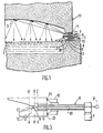
- FIG. 1 a first variant of heating the glass distribution channel is shown according to American patent 3,523,871.
- the distribution channel 2 in which the glass 1 flows is surmounted by a refractory vault 3.
- the air-gas burners used in the patent mentioned above respectively comprise a cylindrical pipe 6 connected at its upstream end to means 7 for premixing air and combustible gas, and the downstream end 8 of which opens out inside a cylindrical bore 9 in a refractory block 10 inserted in the side wall 11 of the supply channel 2.
- the cylindrical bore 9 is extended by a cylindrical coaxial conduit 12 of diameter smaller than that of said bore age 9.
- the cylindrical pipe 6 is capped by a sealing ring 13 which covers the face of the cylindrical bore 9 into which said pipe 6 penetrates.
- Figure 2 is shown an alternative embodiment of Figure 1, wherein a single burner is used, while arch 3 is a flat arch.
- This variant is also an alternative embodiment of said American patent cited above.
- the same elements as those of the previous figure have the same references.
- the cylindrical pipe 6 comes substantially to the plane BB of separation of the bore 9 and the cylindrical coaxial conduit 12, the latter terminating at its other end along the plane AA.
- FIG. 3 represents the device according to the invention and intended to be substituted for devices 1 and / or 5 of the preceding figures.
- a capillary tube 20 is arranged coaxially with the pipe 6, inside the latter.
- the capillary tube is connected at its upstream end to oxygen supply means 21.
- This capillary tube opens at the downstream end 8 of the pipe 6, and extends as far as the cylindrical coaxial conduit 12.
- the downstream end of this capillary tube must not generally go beyond the plane AA in order to avoid its deterioration, clogging, etc. It must necessarily be located beyond the plane C-C representing the downstream end 8 of the pipe 6, in order to avoid the upwelling of oxygen in the premix and the risks of explosion which would result therefrom.
- this downstream end of the capillary tube will be located in the zone where the speed of circulation of the premix is, in general, as high as possible, which, in the embodiment of FIG. 3, is represented by the zone of smaller diameter or cylindrical coaxial conduit 12, located between the planes AA and BB.
- the injection speed of the oxygen from the capillary is sonic so as to have the fastest possible mixture between the air-gas premix and the oxygen.
- the diameter of the capillary is given by the formula mentioned above, that is to say:
- This example is carried out under the same conditions as above but with propane.
- Such a device also has the advantage, when a plurality of these are used in a supply channel, of being able to modulate the over-oxygenation of each and thus modulate the local overheating produced by the different burner devices, without variation in flow rate.
- the air-gas premix used for all burners This modulation is effected only from the oxygen supply manifold, the oxygen supply of each of the devices must of course in this case be separately adjustable (a flow valve adjustable by capillary tube).
- such a device and its implementation method make it possible to increase the temperature of the glass and preferably reheat the edges of the feeder.
- the over-oxygenation allows a moderate increase in the actual temperature of the flame, which results in a moderate increase in the temperature of the refractory block. This results in a significant increase in the radiation from the block to the banks of the channel which are heated by radiation from said block. (We know that this radiation is a function of the power 4 of its temperature.)
- FIG. 4 is an exemplary embodiment of a control system making it possible to modulate the rate of over-oxygenation for each burner.
- Each zone 1, 2, ..., n of the feeder corresponds to a burner device according to the invention (but it is also possible to connect the system to conventional burners since the premix device 50 delivers an air mixture to the pipe 70 / conventional fuel gas).
- Each burner is connected by its lines 6 and 20 to a control module 101, 102, ..., 10n.
- Each module has an inlet 201, 202, ..., 20n for the pipe 70 for supplying air / fuel gas mixture from the premixer 50. Taking into account the fact that all the modules 101, 102, ..., 10n are identical, only the module 101 has been shown in detail and will be described below.
- the pipe 70 is connected to the controlled valve 51 for adjusting the flow, to the mixer 52 from which it comes out to be connected to the cylindrical pipe 6.
- the mixing device 52 receives via the pipe 54 and the controlled valve 53 with adjustable flow rate the combustible gas to be associated with the oxygen (as will be seen below). The latter is sent into the capillary tube 20 via the controlled valve 55 with adjustable flow rate and the pipe 71.
Landscapes
- Chemical & Material Sciences (AREA)
- Engineering & Computer Science (AREA)
- Materials Engineering (AREA)
- Organic Chemistry (AREA)
- Combustion & Propulsion (AREA)
- Physics & Mathematics (AREA)
- Thermal Sciences (AREA)
- Glass Melting And Manufacturing (AREA)
- Gas Burners (AREA)
Claims (8)
Priority Applications (1)
| Application Number | Priority Date | Filing Date | Title |
|---|---|---|---|
| AT86402013T ATE36307T1 (de) | 1985-09-20 | 1986-09-15 | Vorrichtung zur verbesserung der heizung in einem glasverteilungskanal und verfahren zur verwendung dieser vorrichtung. |
Applications Claiming Priority (2)
| Application Number | Priority Date | Filing Date | Title |
|---|---|---|---|
| FR8513949A FR2587695B1 (fr) | 1985-09-20 | 1985-09-20 | Dispositif pour ameliorer le chauffage d'un canal de distribution de verre et procede pour la mise en oeuvre d'un tel dispositif |
| FR8513949 | 1985-09-20 |
Publications (2)
| Publication Number | Publication Date |
|---|---|
| EP0216698A1 EP0216698A1 (de) | 1987-04-01 |
| EP0216698B1 true EP0216698B1 (de) | 1988-08-10 |
Family
ID=9323089
Family Applications (1)
| Application Number | Title | Priority Date | Filing Date |
|---|---|---|---|
| EP86402013A Expired EP0216698B1 (de) | 1985-09-20 | 1986-09-15 | Vorrichtung zur Verbesserung der Heizung in einem Glasverteilungskanal und Verfahren zur Verwendung dieser Vorrichtung |
Country Status (15)
| Country | Link |
|---|---|
| US (1) | US4708728A (de) |
| EP (1) | EP0216698B1 (de) |
| JP (1) | JP2529950B2 (de) |
| KR (1) | KR870003018A (de) |
| AR (1) | AR240892A1 (de) |
| AT (1) | ATE36307T1 (de) |
| AU (1) | AU575535B2 (de) |
| BR (1) | BR8604479A (de) |
| CA (1) | CA1309592C (de) |
| DE (1) | DE3660485D1 (de) |
| DK (1) | DK165058C (de) |
| ES (1) | ES2000898A6 (de) |
| FR (1) | FR2587695B1 (de) |
| PT (1) | PT83396B (de) |
| ZA (1) | ZA867014B (de) |
Families Citing this family (19)
| Publication number | Priority date | Publication date | Assignee | Title |
|---|---|---|---|---|
| DE4222863C2 (de) * | 1992-07-11 | 1995-07-06 | Sorg Gmbh & Co Kg | Brenner für eine regenerative Schmelzwanne mit einem Brennerhals |
| US5346524A (en) * | 1992-09-14 | 1994-09-13 | Schuller International, Inc. | Oxygen/fuel firing of furnaces with massive, low velocity, turbulent flames |
| US5643348A (en) * | 1992-09-14 | 1997-07-01 | Schuller International, Inc. | Oxygen/fuel fired furnaces having massive, low velocity, turbulent flame clouds |
| US5405082A (en) * | 1993-07-06 | 1995-04-11 | Corning Incorporated | Oxy/fuel burner with low volume fuel stream projection |
| US5500030A (en) * | 1994-03-03 | 1996-03-19 | Combustion Tec, Inc. | Oxy-gas fired forehearth burner system |
| FR2735122A1 (fr) * | 1995-06-08 | 1996-12-13 | Saint Gobain Emballage | Dispositif de combustion |
| US5814121A (en) * | 1996-02-08 | 1998-09-29 | The Boc Group, Inc. | Oxygen-gas fuel burner and glass forehearth containing the oxygen-gas fuel burner |
| DE59701362D1 (de) * | 1997-07-14 | 2000-05-04 | Ernst Vieler | Verfahren und Vorrichtung zur Bestimmung und Regelung des Sauerstoffgehalts in der Ofenatmosphäre eines Glasfeeders |
| US6237369B1 (en) | 1997-12-17 | 2001-05-29 | Owens Corning Fiberglas Technology, Inc. | Roof-mounted oxygen-fuel burner for a glass melting furnace and process of using the oxygen-fuel burner |
| US6029910A (en) * | 1998-02-05 | 2000-02-29 | American Air Liquide, Inc. | Low firing rate oxy-fuel burner |
| KR20000020505A (ko) * | 1998-09-22 | 2000-04-15 | 박영구 | 유리용해로의 산소공급 제어장치 |
| KR20000050536A (ko) * | 1999-01-11 | 2000-08-05 | 서두칠 | 유리용융로 |
| KR100438413B1 (ko) * | 1999-01-11 | 2004-07-02 | 한국전기초자 주식회사 | 유리용융로 |
| US6233974B1 (en) | 1999-01-25 | 2001-05-22 | Combustion Tec | Oxygen-gaseous forehearth burner for air-fuel and oxy-fuel forehearth burner block geometries |
| EP1889816A1 (de) * | 2006-08-15 | 2008-02-20 | Rockwool International A/S | Verfahren und Vorrichtung zur Herstellung von Mineralfasern |
| EP2063175A1 (de) * | 2007-11-22 | 2009-05-27 | L'AIR LIQUIDE, Société Anonyme pour l'Etude et l'Exploitation des Procédés Georges Claude | Oxybrenner |
| FR2924201B1 (fr) * | 2007-11-23 | 2013-08-16 | Air Liquide | Procede de chauffage au moyen d'un oxybruleur comportant un injecteur dispose a l'interieur d'un bloc |
| EP2392857A1 (de) | 2010-06-07 | 2011-12-07 | L'Air Liquide Société Anonyme pour l'Etude et l'Exploitation des Procédés Georges Claude | Sauerstoff-Brennstoff-Brenner |
| GB201418727D0 (en) * | 2014-10-21 | 2014-12-03 | Five Stein Ltd | Forehearths and burner blocks for use therein |
Family Cites Families (9)
| Publication number | Priority date | Publication date | Assignee | Title |
|---|---|---|---|---|
| US2499207A (en) * | 1945-12-22 | 1950-02-28 | John J Wolfersperger | Pressure-type burner and method of burning fuel |
| US3321288A (en) * | 1964-02-28 | 1967-05-23 | Owens Corning Fiberglass Corp | Method for controlling the temperature of heat-softenable material |
| FR1450020A (fr) * | 1965-10-04 | 1966-05-06 | Australian Gas Light Company | Perfectionnements au chauffage des connexions de feeders utilisées dans l'industrie du verre pour alimenter des machines à mouler |
| FR1479461A (fr) * | 1966-03-22 | 1967-05-05 | Saint Gobain | Perfectionnements aux canaux amenant le verre fondu à des postes de travail |
| DE1903595A1 (de) * | 1968-01-25 | 1969-10-09 | Daido Sanso Kabushiki Kaisha O | Verfahren und Vorrichtung zum fortlaufenden Erzeugen einer Flamme von hoher Temperatur |
| US3954433A (en) * | 1974-08-22 | 1976-05-04 | Owens-Corning Fiberglas Corporation | Method of and apparatus for coordinating the application of heat to a melt from sources above and below the melt surface |
| SU643717A1 (ru) * | 1977-01-10 | 1979-01-25 | Всесоюзный научно-исследовательский институт природных газов | Способ реформировани жидкого топлива |
| FR2546155B1 (fr) * | 1983-05-20 | 1986-06-27 | Air Liquide | Procede et installation d'elaboration de verre |
| FR2567118B1 (fr) * | 1984-07-04 | 1986-11-14 | Air Liquide | Procede de chauffage d'un canal contenant du verre a l'aide de flammes oxy-combustibles |
-
1985
- 1985-09-20 FR FR8513949A patent/FR2587695B1/fr not_active Expired
-
1986
- 1986-09-15 AT AT86402013T patent/ATE36307T1/de not_active IP Right Cessation
- 1986-09-15 ZA ZA867014A patent/ZA867014B/xx unknown
- 1986-09-15 DE DE8686402013T patent/DE3660485D1/de not_active Expired
- 1986-09-15 EP EP86402013A patent/EP0216698B1/de not_active Expired
- 1986-09-16 ES ES8601921A patent/ES2000898A6/es not_active Expired
- 1986-09-16 US US06/908,351 patent/US4708728A/en not_active Expired - Lifetime
- 1986-09-17 AU AU62981/86A patent/AU575535B2/en not_active Ceased
- 1986-09-17 DK DK445186A patent/DK165058C/da not_active IP Right Cessation
- 1986-09-18 PT PT83396A patent/PT83396B/pt not_active IP Right Cessation
- 1986-09-18 BR BR8604479A patent/BR8604479A/pt not_active IP Right Cessation
- 1986-09-19 JP JP61219867A patent/JP2529950B2/ja not_active Expired - Lifetime
- 1986-09-19 CA CA000518658A patent/CA1309592C/fr not_active Expired - Lifetime
- 1986-09-19 AR AR305308A patent/AR240892A1/es active
- 1986-09-20 KR KR1019860007892A patent/KR870003018A/ko not_active Withdrawn
Also Published As
| Publication number | Publication date |
|---|---|
| DK165058C (da) | 1993-02-22 |
| EP0216698A1 (de) | 1987-04-01 |
| DK445186D0 (da) | 1986-09-17 |
| DE3660485D1 (en) | 1988-09-15 |
| AR240892A1 (es) | 1991-03-27 |
| US4708728A (en) | 1987-11-24 |
| FR2587695A1 (fr) | 1987-03-27 |
| DK165058B (da) | 1992-10-05 |
| FR2587695B1 (fr) | 1987-11-20 |
| AU575535B2 (en) | 1988-07-28 |
| ATE36307T1 (de) | 1988-08-15 |
| PT83396A (fr) | 1986-10-01 |
| CA1309592C (fr) | 1992-11-03 |
| PT83396B (pt) | 1992-10-30 |
| BR8604479A (pt) | 1987-05-19 |
| JPS6269010A (ja) | 1987-03-30 |
| KR870003018A (ko) | 1987-04-14 |
| AU6298186A (en) | 1987-03-26 |
| AR240892A2 (es) | 1991-03-27 |
| ES2000898A6 (es) | 1988-03-16 |
| ZA867014B (en) | 1987-04-29 |
| DK445186A (da) | 1987-03-21 |
| JP2529950B2 (ja) | 1996-09-04 |
Similar Documents
| Publication | Publication Date | Title |
|---|---|---|
| EP0216698B1 (de) | Vorrichtung zur Verbesserung der Heizung in einem Glasverteilungskanal und Verfahren zur Verwendung dieser Vorrichtung | |
| KR102317066B1 (ko) | 이중-단계화된 산소-연료 버너 | |
| EP2731918B1 (de) | Glasschmelzanlage und verfahren | |
| CA1253745A (fr) | Bruleur a charbon pulverise | |
| KR101539483B1 (ko) | 버너 조립체 및 연소 방법 | |
| EP0643262B1 (de) | Verbrennungsverfahren | |
| FR2913971A1 (fr) | Dispositif de fusion du verre comprenant deux fours | |
| EP0782973A1 (de) | Verfahren zum Erhitzen der Charge eines Glasschmelzofens | |
| FR2462658A1 (fr) | Procede et appareil pour le sechage et le broyage fin du charbon, pour l'alimentation d'un foyer a poussier de charbon | |
| EP0481835B1 (de) | Verfahren zur Erwärmung eines thermischen Hohlraums und Brenner | |
| FR2757844A1 (fr) | Procede de fabrication de verre technique et bruleur pour la mise en oeuvre d'un tel procede | |
| EP2546204A1 (de) | Verfahren und Installation zum Glasschmelzen | |
| EP0597761A1 (de) | Deponie und Verfahren zur Verglasung von Abfällen | |
| FR2484610A1 (fr) | Procede pour l'obtention d'un melange de gaz et d'air et four a gaz pour la mise en oeuvre du procede | |
| FR2670801A1 (fr) | Dispositif d'allumage d'un lit de melange de materiaux tels que du minerai et du coke. | |
| EP1625098B1 (de) | Verfahren zum regeln von oxyfuel-brennern durch einspritzung von einem zusatzgas | |
| EP0011564B1 (de) | Verfahren und Vorrichtung zum Regeln der Produktion thermoplastischer Mineralfasern | |
| FR2926350A1 (fr) | Procede et four de fusion. | |
| EP0079264A1 (de) | Verfahren zum Stückigmachen von Eisenerzen auf einem Wanderrost und Vorrichtung zur Durchführung des Verfahrens | |
| BE697455A (de) | ||
| BE821191A (fr) | Bruleur a impulsion et installation equipee d'un tel bruleur | |
| EP2141129A1 (de) | Brenneranlage mit erhöhter Flexibilität | |
| FR2573183A1 (fr) | Generateur d'air chaud a combustibles solides a multiples usages notamment en cimenterie |
Legal Events
| Date | Code | Title | Description |
|---|---|---|---|
| PUAI | Public reference made under article 153(3) epc to a published international application that has entered the european phase |
Free format text: ORIGINAL CODE: 0009012 |
|
| 17P | Request for examination filed |
Effective date: 19860918 |
|
| AK | Designated contracting states |
Kind code of ref document: A1 Designated state(s): AT BE CH DE FR GB IT LI LU NL SE |
|
| 17Q | First examination report despatched |
Effective date: 19880126 |
|
| ITF | It: translation for a ep patent filed | ||
| GRAA | (expected) grant |
Free format text: ORIGINAL CODE: 0009210 |
|
| AK | Designated contracting states |
Kind code of ref document: B1 Designated state(s): AT BE CH DE FR GB IT LI LU NL SE |
|
| PG25 | Lapsed in a contracting state [announced via postgrant information from national office to epo] |
Ref country code: GB Free format text: LAPSE BECAUSE OF NON-PAYMENT OF DUE FEES Effective date: 19880810 |
|
| REF | Corresponds to: |
Ref document number: 36307 Country of ref document: AT Date of ref document: 19880815 Kind code of ref document: T |
|
| REF | Corresponds to: |
Ref document number: 3660485 Country of ref document: DE Date of ref document: 19880915 |
|
| GBV | Gb: ep patent (uk) treated as always having been void in accordance with gb section 77(7)/1977 [no translation filed] | ||
| PLBE | No opposition filed within time limit |
Free format text: ORIGINAL CODE: 0009261 |
|
| STAA | Information on the status of an ep patent application or granted ep patent |
Free format text: STATUS: NO OPPOSITION FILED WITHIN TIME LIMIT |
|
| 26N | No opposition filed | ||
| ITTA | It: last paid annual fee | ||
| EPTA | Lu: last paid annual fee | ||
| PGFP | Annual fee paid to national office [announced via postgrant information from national office to epo] |
Ref country code: LU Payment date: 19940801 Year of fee payment: 9 |
|
| PGFP | Annual fee paid to national office [announced via postgrant information from national office to epo] |
Ref country code: CH Payment date: 19940812 Year of fee payment: 9 Ref country code: AT Payment date: 19940812 Year of fee payment: 9 |
|
| PGFP | Annual fee paid to national office [announced via postgrant information from national office to epo] |
Ref country code: SE Payment date: 19940815 Year of fee payment: 9 |
|
| EAL | Se: european patent in force in sweden |
Ref document number: 86402013.6 |
|
| PG25 | Lapsed in a contracting state [announced via postgrant information from national office to epo] |
Ref country code: LU Free format text: LAPSE BECAUSE OF NON-PAYMENT OF DUE FEES Effective date: 19950915 Ref country code: AT Effective date: 19950915 |
|
| PG25 | Lapsed in a contracting state [announced via postgrant information from national office to epo] |
Ref country code: SE Effective date: 19950916 |
|
| PG25 | Lapsed in a contracting state [announced via postgrant information from national office to epo] |
Ref country code: LI Effective date: 19950930 Ref country code: CH Effective date: 19950930 |
|
| REG | Reference to a national code |
Ref country code: CH Ref legal event code: PL |
|
| EUG | Se: european patent has lapsed |
Ref document number: 86402013.6 |
|
| PGFP | Annual fee paid to national office [announced via postgrant information from national office to epo] |
Ref country code: FR Payment date: 20000807 Year of fee payment: 15 |
|
| PGFP | Annual fee paid to national office [announced via postgrant information from national office to epo] |
Ref country code: NL Payment date: 20000814 Year of fee payment: 15 |
|
| PGFP | Annual fee paid to national office [announced via postgrant information from national office to epo] |
Ref country code: DE Payment date: 20000823 Year of fee payment: 15 |
|
| PGFP | Annual fee paid to national office [announced via postgrant information from national office to epo] |
Ref country code: BE Payment date: 20000908 Year of fee payment: 15 |
|
| PG25 | Lapsed in a contracting state [announced via postgrant information from national office to epo] |
Ref country code: BE Free format text: LAPSE BECAUSE OF NON-PAYMENT OF DUE FEES Effective date: 20010930 |
|
| BERE | Be: lapsed |
Owner name: L' AIR LIQUIDE S.A. POUR L'ETUDE ET L'EXPLOITATION Effective date: 20010930 |
|
| PG25 | Lapsed in a contracting state [announced via postgrant information from national office to epo] |
Ref country code: NL Free format text: LAPSE BECAUSE OF NON-PAYMENT OF DUE FEES Effective date: 20020401 |
|
| PG25 | Lapsed in a contracting state [announced via postgrant information from national office to epo] |
Ref country code: DE Free format text: LAPSE BECAUSE OF NON-PAYMENT OF DUE FEES Effective date: 20020501 |
|
| PG25 | Lapsed in a contracting state [announced via postgrant information from national office to epo] |
Ref country code: FR Free format text: LAPSE BECAUSE OF NON-PAYMENT OF DUE FEES Effective date: 20020531 |
|
| NLV4 | Nl: lapsed or anulled due to non-payment of the annual fee |
Effective date: 20020401 |
|
| REG | Reference to a national code |
Ref country code: FR Ref legal event code: ST |
|
| NLV4 | Nl: lapsed or anulled due to non-payment of the annual fee |
Effective date: 20020401 |
|
| PG25 | Lapsed in a contracting state [announced via postgrant information from national office to epo] |
Ref country code: IT Free format text: LAPSE BECAUSE OF NON-PAYMENT OF DUE FEES Effective date: 20050915 |