EP0216706B1 - Verfahren und Vorrichtung zur Messung des Brodelpunktes von Petroleum in einer unterirdischen Schicht - Google Patents
Verfahren und Vorrichtung zur Messung des Brodelpunktes von Petroleum in einer unterirdischen Schicht Download PDFInfo
- Publication number
- EP0216706B1 EP0216706B1 EP86402077A EP86402077A EP0216706B1 EP 0216706 B1 EP0216706 B1 EP 0216706B1 EP 86402077 A EP86402077 A EP 86402077A EP 86402077 A EP86402077 A EP 86402077A EP 0216706 B1 EP0216706 B1 EP 0216706B1
- Authority
- EP
- European Patent Office
- Prior art keywords
- chamber
- needle
- pressure
- volume
- orifice
- Prior art date
- Legal status (The legal status is an assumption and is not a legal conclusion. Google has not performed a legal analysis and makes no representation as to the accuracy of the status listed.)
- Expired - Lifetime
Links
Images


Classifications
-
- G—PHYSICS
- G01—MEASURING; TESTING
- G01N—INVESTIGATING OR ANALYSING MATERIALS BY DETERMINING THEIR CHEMICAL OR PHYSICAL PROPERTIES
- G01N33/00—Investigating or analysing materials by specific methods not covered by groups G01N1/00 - G01N31/00
- G01N33/26—Oils; Viscous liquids; Paints; Inks
- G01N33/28—Oils, i.e. hydrocarbon liquids
-
- E—FIXED CONSTRUCTIONS
- E21—EARTH OR ROCK DRILLING; MINING
- E21B—EARTH OR ROCK DRILLING; OBTAINING OIL, GAS, WATER, SOLUBLE OR MELTABLE MATERIALS OR A SLURRY OF MINERALS FROM WELLS
- E21B49/00—Testing the nature of borehole walls; Formation testing; Methods or apparatus for obtaining samples of soil or well fluids, specially adapted to earth drilling or wells
- E21B49/08—Obtaining fluid samples or testing fluids, in boreholes or wells
-
- E—FIXED CONSTRUCTIONS
- E21—EARTH OR ROCK DRILLING; MINING
- E21B—EARTH OR ROCK DRILLING; OBTAINING OIL, GAS, WATER, SOLUBLE OR MELTABLE MATERIALS OR A SLURRY OF MINERALS FROM WELLS
- E21B49/00—Testing the nature of borehole walls; Formation testing; Methods or apparatus for obtaining samples of soil or well fluids, specially adapted to earth drilling or wells
- E21B49/08—Obtaining fluid samples or testing fluids, in boreholes or wells
- E21B49/081—Obtaining fluid samples or testing fluids, in boreholes or wells with down-hole means for trapping a fluid sample
- E21B49/082—Wire-line fluid samplers
-
- E—FIXED CONSTRUCTIONS
- E21—EARTH OR ROCK DRILLING; MINING
- E21B—EARTH OR ROCK DRILLING; OBTAINING OIL, GAS, WATER, SOLUBLE OR MELTABLE MATERIALS OR A SLURRY OF MINERALS FROM WELLS
- E21B49/00—Testing the nature of borehole walls; Formation testing; Methods or apparatus for obtaining samples of soil or well fluids, specially adapted to earth drilling or wells
- E21B49/08—Obtaining fluid samples or testing fluids, in boreholes or wells
- E21B49/087—Well testing, e.g. testing for reservoir productivity or formation parameters
- E21B49/0875—Well testing, e.g. testing for reservoir productivity or formation parameters determining specific fluid parameters
-
- G—PHYSICS
- G01—MEASURING; TESTING
- G01N—INVESTIGATING OR ANALYSING MATERIALS BY DETERMINING THEIR CHEMICAL OR PHYSICAL PROPERTIES
- G01N7/00—Analysing materials by measuring the pressure or volume of a gas or vapour
Definitions
- the present invention relates to the measurement of the oil bubble point of an underground formation in which a well has been drilled.
- the monophasic state of the oil taken from the well is verified by measuring the bubble point of the samples brought to the surface, i.e. the pressure above which the gases mixed with the oil are there. fully dissolved, so that the oil is presented as a monophasic liquid. Knowing the pressure and the temperature which prevail at the bottom of the well, at the place of sampling, we deduce if the oil which is there is in the monophasic state.
- Such a bubble point measurement performed in the laboratory, requires a recompression of the oil to a pressure of the order prevailing in the well, as well as heating to the temperature of the underground deposit.
- Patent FR-A-2 476 205 describes a method and a device for hydrodynamic study of a well.
- a sample of fluid with a volume smaller than the sampling chamber is taken, the sample is hermetically closed and its volume is increased.
- the pressure and the volume increase are recorded in order to obtain the bubble point of the sampled fluid.
- the pressure is always lower than the value at which the sample was taken.
- the object of the invention is to remedy the above drawbacks, by carrying out a rapid measurement directly in the well, making it possible to verify the validity of the samples taken.
- a method for measuring the bubble point of petroleum of a the underground formation in which a well has been drilled comprises the steps of claim 1.
- a device for measuring the bubble point of petroleum in an underground formation in which a well has been drilled comprises the tool of claim 2.
- the movable needle of the device comprises two successive parts of different section, namely a first part which is extended by a second part of section smaller than that of the first, while the chamber has two aligned orifices allowing the needle to pass right through the chamber, namely a first orifice of cross section conjugate with that of the first part of the needle and a second orifice of cross section conjugate with that of the second part, these orifices being closed respectively by said parts of the needle when the latter is brought to pass through the chamber.
- the latter is completely isolated from the external environment and that the small amount of oil which is confined therein is subjected to pressure variations resulting from the volume variations created by the movements of the needle , the volume offered to the oil depending on the variable proportion between the respective lengths of its first and second parts which are included inside the chamber.
- the means for driving the needle cause it to withdraw completely from the chamber by freeing the orifice or orifices which it comprises, the chamber is placed in communication with the external medium and is filled with petroleum.
- a first calibrated valve and a second calibrated pressure limiting valve are provided between the interior volume of the chamber and the external medium, to respectively limit the overpressure and the depression which may appear in the chamber, during the movements of the 'needle, relative to the pressure prevailing in the well.
- the needle drive means may comprise an electric motor housed in a sealed pressure-proof casing, a threaded rod driven in rotation by the motor through the wall of its casing by means of a coupling device magnetic, and a nut mounted on the threaded rod and integral with the needle, which it animates with longitudinal translation movements when the motor rotates the threaded rod.
- the displacement sensor measuring the movements of the needle it can be constituted by a linear potentiometer.
- the invention described in the foregoing makes it possible to obtain, directly in the well, a good approximation of the bubble point of the oil that it contains, which makes it possible to validate any sample taken in the well and to benefit from a control. the quality of the samples on the site of operation. If for some reason the sample was not validated, the operations of taking the sample and validating the new sample taken could be restarted while the measuring device is still in the well.
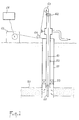
- FIG. 1 schematically represents, in vertical section, an oil well into which a measuring device according to the invention has been lowered.
- FIG. 2 represents a pressure / volume curve making it possible to determine the bubble point of a liquid-gas mixture.
- FIG. 3 shows, schematically and in a simplified manner, the structure of a measuring device according to the invention.
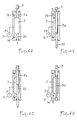
- FIGS. 4a to 4d schematically illustrate the successive phases of a bubble point measurement operation according to the invention.
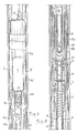
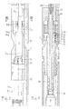
- Figures 5 to 9 show in longitudinal section different parts of a device according to the invention, distributed over its length, according to a concrete embodiment.
- FIG. 10 represents a cross section along the line X-X of FIG. 6.
- FIG. 11 schematically represents the configuration of the linear potentiometer constituting a displacement sensor.
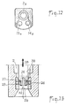
- FIG. 12 represents a cross section along the line XII-XII of FIG. 7.
- Figure 13 shows, on a slightly enlarged scale, a longitudinal section of the end of the movable needle belonging to the device, showing the pressure equalization duct.
- FIG. 1 shows a well dug in an oil-producing zone 50 and comprising, in a casing 51, a production column 52. Between the lower end of the latter and the casing 51 is placed an annular sealing device 53. A measuring device 60 according to the invention is lowered to the level of the producing zone 50 using a cable 61 to which it is suspended. This cable, passing inside the production column 52, emerges at its top through a sealing device 62 to be wound, via deflection pulleys 63, 64, on the drum of a winch 65 arranged on the surface of the ground.
- the cable 61 is an electric cable which, in addition to a mechanical suspension function of the measurement device 60, provides a function of transmission of measurement signals to the surface and of control signals to the device 60, as well as to other devices. which can be associated with the latter, in particular sampling capacities whose triggering is controlled from the surface. These signals are managed by a computer 66 constituting a control and recording unit.
- the operation of the measuring device 60 is based on the diagram in FIG. 2 showing the variations in pressure as a function of the volume of a liquid-gas mixture, the gas offering a some solubility in the liquid.
- a given pressure variation results in a small variation in the volume of the mixture.
- gas bubbles appear in the mixture and the volume varies much more for the same pressure variation.
- the PDB pressure is the "bubble point", above which it is certain that the mixture is completely liquid and does not contain any fraction in the gaseous state.
- the apparatus essentially comprises a long casing 1 in the form of a cylinder of revolution, a chamber 2 with a thick wall, inside which a needle 3 having two parts 3a, 3b of different diameters can be inserted , this needle can be driven in longitudinal translation movements by a mechanism composed of a cylindrical piece 4 at one end of which is fixed the needle 3 and which is integral at its other end with a nut 5 mounted on a threaded rod 6 driven in rotation by an electric motor 7 placed in a sealed casing 15, by means of a magnetic coupling device 8. Above the motor 7 is the electronic control part of the tool, as well as '' a connector which makes it possible to connect the device either directly to an electric cable going up to the surface, or to another device.
- the motor 7 When the motor 7 is started, in one direction or the other, it rotates the threaded rod 6, so that the nut 5 moves in the longitudinal direction thereof, driving in translation the part 4 , which is prevented from rotating by a fixed lug 9 engaged in a rectilinear guide groove 10 belonging to the part 4, the latter making penetrate into the chamber 2 the needle 3 or bringing it out according to the direction of rotation of the motor 7.
- the interior volume of the chamber 2 varies, which induces variations in the pressure to which the fluid contained in said chamber is subjected, which is measured using a pressure gauge 11.
- the volume of chamber 2 is deduced from the longitudinal position of the part 4 carrying the needle 3, known from a linear potentiometer 12 measuring the displacements of said part relative to the casing 1 of the device.
- the device also includes a thermometric probe for measuring the temperature of the oil in the well.
- the values measured by this probe are transmitted to the surface, like those delivered by the pressure gauge 11 and the potentiometer 12.
- the needle 3 is completely removed from the chamber 2, freeing the orifices 2a, 2b made in alignment in the wall of the chamber 2 to allow the needle to pass.
- the fluid which is the subject of the measurement can then pass freely through the chamber 2, either by natural circulation of the fluid at the level of the device, or by virtue of a vertical displacement imparted to the latter in the well where it has been lowered.
- the chamber 2 is then filled with a small quantity of the fluid, under the pressure P1 prevailing in the well.
- the needle 3 is made to enter the chamber 2.
- the orifices 2a and 2b the diameter of which is respectively equal to the diameter of the parts 3a and 3b of the needle, are then closed so sealed by the latter, and, the fluid present in the chamber 2 is confined therein under a certain volume.
- the needle 3 continuing its course, its part 3a enters the chamber and reduces the volume which the latter offers to the fluid (FIG. 4b), which is consequently subjected to an increasing pressure, greater than P1.
- the needle 3 having reached its maximum insertion position where the portion contained in the chamber 2 belongs almost exclusively to its part 3a of larger diameter, the motor 7 is stopped, then restarted step by step in the other direction, so that it causes extraction in stages of the needle 3, resulting in a gradual increase in the volume of the chamber 2, the part 3a gradually giving way to the part 3b of smaller diameter .
- this last part has a sufficient length to keep the orifice 2b which it crosses closed, and this substantially until the part 3a has completely left the chamore 2.
- the pressure P of the fluid decreases, and it is measured by the pressure gauge 11 while the increasing volume of the chamber is determined from the position of the needle 3 measured by the potentiometer 12.
- Figures 5 to 9 show a concrete embodiment of a device according to the invention. They show the internal structure of successive portions of the device, according to the order of numbering of the figures, from top to bottom when the device is in place in the production column of an oil well.
- the interior space of the device which extends between the sealed electrical bushings 31 situated above the motor 7 (FIG. 5) and the sealed electrical bushings provided in a zone 39 situated at the other end of the device (FIG. 9) is filled with an insulating fluid (mineral oil).
- this fluid is maintained at the same pressure as that of the well by means of a floating piston 40 ( Figure 7) ensuring the separation between the tributary of the well and the insulating fluid internal to the device.
- the separation piston 40, through which the needle 3 passes, is pushed by a spring 41 to maintain the insulating oil inside the device under slight overpressure. The latter allows the device to operate in a high pressure environment, in possibly corrosive or conductive fluids.
- the potentiometer 12 comprises, on a flat support 12a made of insulating material, mounted longitudinally on the part 4, three rectilinear tracks 12b, 12c, 12d electrically conductive, arranged geometrically in parallel and electrically in series . On these tracks, among which the end tracks 12b 12d have almost zero resistivity, the intermediate track 12c forming the resistive track of the potentiometer, rub three fixed brushes 12e which constitute the three terminals of the potentiometer 12.
- FIGS. 8 and 12 show that the two valves 13, 14, capable of bringing the interior of the chamber 2 into communication with the external environment, are arranged on the same side of the said chamber, in housings 13a, 14a dug side by side in one end of the wall of the chamber.
- FIG 13 it shows the structure of the end of the end portion 3b of the needle 3.
- this end is hollowed out a channel 26 opening on the one hand into the front face 32 through which terminates the needle and on the other hand in a peripheral groove 27 hollowed out in the lateral surface of the needle, at a distance from its front face 32 slightly greater than the thickness of the seal 24.
- a bundle of electrical connection wires 42 passes right through the device through a tunnel 43 provided in its envelope 1.
- the watertight crossing of the area 39 (FIG. 9) comprises a watertight crossing itself 70 terminated at its two ends by two pins 71 and 72 each connected to a socket 73 and 74 respectively.
- the end 75 of the bundle of electrical wires 42 is connected to the electrical part (not shown) of the pressure sensor 11, located under said sensor.
- Chamber 2 is produced in the form of an independent element next to which said tunnel 43 passes (FIG. 8); it can be easily detached from the casing 1 to allow access to the seals 24, without the need to extract the bundle of electrical wires 42 passing through the device.
- a device as described above is designed exclusively for analyzing the characteristics of petroleum at the bottom of a well by measuring its bubble point, and is not suitable for bringing samples to the surface. of oil taken from the bottom. For this reason, it is convenient in practice to combine this device with at least one sampler in a multi-tool set.
- a device according to the invention makes it possible to carry out repeated measurements as many times as desired during a period of production of the well.
Landscapes
- Life Sciences & Earth Sciences (AREA)
- Engineering & Computer Science (AREA)
- Geology (AREA)
- Mining & Mineral Resources (AREA)
- Physics & Mathematics (AREA)
- Chemical & Material Sciences (AREA)
- Health & Medical Sciences (AREA)
- Environmental & Geological Engineering (AREA)
- Fluid Mechanics (AREA)
- General Life Sciences & Earth Sciences (AREA)
- Geochemistry & Mineralogy (AREA)
- General Health & Medical Sciences (AREA)
- Analytical Chemistry (AREA)
- Biochemistry (AREA)
- General Physics & Mathematics (AREA)
- Immunology (AREA)
- Pathology (AREA)
- Oil, Petroleum & Natural Gas (AREA)
- General Chemical & Material Sciences (AREA)
- Food Science & Technology (AREA)
- Medicinal Chemistry (AREA)
- Chemical Kinetics & Catalysis (AREA)
- Measuring Fluid Pressure (AREA)
- Sampling And Sample Adjustment (AREA)
Claims (9)
- Verfahren zum Messen des Brodelpunktes von Erdöl einer unterirdischen Formation, in die ein Bohrloch abgeteuft worden ist, umfassend die folgenden Schritte: Absenken einer Sonde in das Bohrloch mit einer Kammer, deren Volumen gesteuert variierbar ist, Öffnen der Kammer derart, daß sie sich mit Erdöl füllt, Wiederverschließen der Kammer und graduelles Vergrößern ihres Volumens und Messen des in ihr herrschenden Druckes P für jedes der Kammer aufgezwungene Volumen V, Etablieren, ausgehend von den so bestimmten Meßpunkten, der Kurve P=f(V), aus der die Position des Brodelpunktes ableitbar ist, dadurch gekennzeichnet, daß nach Schließen der erdölgefüllten Kammer zuerst eine Verringerung des Volumens derselben bewirkt wird derart, daß ein Überdruck relativ zu dem Umgebungsdruck des Erdöls in dem Bohrloch erzeugt wird, bevor nach und nach das Volumen der Kammer unter Festhalten der sukzessiven Werte von Volumen und Druck vergrößert wird.
- Vorrichtung zum Messen des Brodelpunktes von Erdöl einer unterirdischen Formation, in die ein Bohrloch abgetsuft worden ist, umfassend eine in das Bohrloch ablaßbare Sonde mit einer Kammer (2) mit starrer Wandung, deren Volumen mittels eines unter der Wirkung von Antriebsmitteln in Längsrichtung translatorisch verlagerbaren Organs variierbar ist, welche Kammer (2), deren Öffnen für Ihre Füllung steuerbar ist, mit einem den in ihr herrschenden Druck messenden Manometer (11) verbunden ist, und einen mit dem Organ (3) verbundenen Verlagerungsfühler (2), wobei die von dem Manometer und dem Verlagerungsfühler gelieferten Signale die Bestimmung des Brodelpunktes ermöglichen, dadurch gekennzeichnet, daß die Kammer (2) eine die Wandung durchsetzende Öffnung (2b) aufweist und daß das Organ (3) als eine in die Kammer durch die Öffnung einführbare Nadel (3) zum Variieren des Volumens der Kammer (2) ausgebildet ist, welche Nadel (3) die Öffnung (2b) für das Füllen der Kammer öffnen kann.
- Vorrichtung nach Anspruch 2, dadurch gekennzeichnet, daß die Nadel (3) zwei aufeinanderfolgende Abschnitte (3a, 3b) unterschiedlichen Querschnitts aufweist, nämlich einen ersten Abschnitt (3a), der sich um einen zweiten Abschitt (3b) geringeren Querschnitts als der erste verlängert, und daß die Kammer (2) zwei ausgefluchtete Öffnungen (2a, 2b) besitzt, die es der Nadel (3) ermöglichen, die Kammer von einer zur anderen Seite zu durchsetzen, nämlich eine erste Öffnung (2a) eines zum Querschnitt des ersten Nadelabschnitts (3a) komplementären Querschnitts und eine zweite Öffnung (2b) eines zum Querschnitt des zweiten Nadelabschnitt (3b) komplementären Querschnitts, welche Öffnungen jeweils durch die Abschnitte der Nadel (3) gesperrt sind, wenn die Nadel zum Durchsetzen der Kammer gebracht ist.
- Vorrichtung nach Anspruch 3, dadurch gekennzeichnet, daß die Antriebsmittel der Nadel (3) diese vollständig aus der Kammer (2) zurückziehen können unter Freigabe der beiden Öffnungen (2a, 2b).
- Vorrichtung nach einem der Ansprüche 2 bis 4, dadurch gekennzeichnet, daß ein erstes tariertes Druckbegrenzungsventil (13) zwischen dem inneren Volumen der Kammer (2) und dem äußeren Milieu angeordnet ist, das den Überdruck P begrenzt, der in der Kammer relativ zu dem im Bohrloch herrschenden Druck P1 auftreten kann.
- Vorrichtung nach einem der Ansprüche 2 bis 5, dadurch gekennzeichnet, daß ein zweites tariertes Druckbegrenzungsventil (14) zwischen dem inneren Volumen der Kammer (2) und dem äußeren Milieu angeordnet ist, das den Unterdruck P' begrenzt, der in der Kammer relativ zu dem im Bohrloch herrschenden Druck P1 auftreten kann.
- Vorrichtung nach einem der Ansprüche 2 bis 6, dadurch gekennzeichnet, daß die Antriebsmittel der Nadel (3) einen Elektromotor (7) in einemn druckfest abgedichteten Gehäuse (15), eine von dem Motor (7) durch die Gehäusewandung hindurch mittels einer Magnetkupplung (8) zum Umlauf angetriebene Gewindespindel (6) und eine auf der Gewindespindel (6) angeordnete, mit der Nadel (3) verbundene Mutter (5) umfassen.
- Vorrichtung nach einem der Ansprüche 2 bis 7, dadurch gekennzeichnet, daß der Verlagerungsfühler der Nadel (3) von einem linearen Potentiometer (12) gebildet ist.
- Vorrichtung nach einem der Ansprüche 3 bis 8, dadurch gekennzeichnet, daß die Öffnung (2b) der Kammer (2), die mit dem zweiten Abschnitt (3b) der Nadel (3) in Wirkverbindung bringbar ist, mit einer Ringdichtung (24) versehen ist und daß in das Ende der Nadel (3) eine Druckausgleichsleitung (26) eingearbeitet ist, welche -- wenn die Nadel bei einer Rückzugsbewegung aus der Kammer an der Öffnung (2b) vorbeistreicht - - die Kammer mit dem äußeren Milieu in Kommunikation bringt, während das Nadelende noch in der Dichtung (24) sitzt.
Applications Claiming Priority (2)
| Application Number | Priority Date | Filing Date | Title |
|---|---|---|---|
| FR8514060A FR2587800B1 (fr) | 1985-09-23 | 1985-09-23 | Procede et dispositif de mesure du point de bulle du petrole d'une formation souterraine |
| FR8514060 | 1985-09-23 |
Publications (2)
| Publication Number | Publication Date |
|---|---|
| EP0216706A1 EP0216706A1 (de) | 1987-04-01 |
| EP0216706B1 true EP0216706B1 (de) | 1992-05-13 |
Family
ID=9323150
Family Applications (1)
| Application Number | Title | Priority Date | Filing Date |
|---|---|---|---|
| EP86402077A Expired - Lifetime EP0216706B1 (de) | 1985-09-23 | 1986-09-23 | Verfahren und Vorrichtung zur Messung des Brodelpunktes von Petroleum in einer unterirdischen Schicht |
Country Status (5)
| Country | Link |
|---|---|
| US (1) | US4782695A (de) |
| EP (1) | EP0216706B1 (de) |
| CA (1) | CA1288614C (de) |
| DE (1) | DE3685280D1 (de) |
| FR (1) | FR2587800B1 (de) |
Families Citing this family (33)
| Publication number | Priority date | Publication date | Assignee | Title |
|---|---|---|---|---|
| US4783989A (en) * | 1987-03-05 | 1988-11-15 | Atlantic Richfield Company | Vapor pressure measurement apparatus and method |
| US5291796A (en) * | 1991-07-30 | 1994-03-08 | Halliburton Company | Apparatus and method for draining high pressure fluid samples without mercury |
| USRE38052E1 (en) | 1992-05-01 | 2003-04-01 | Sensor Dynamics, Limited | Sensing apparatus for sensing pressure or temperature in oil wells, including transmitter relaying pressure or temperature information to a remote control point |
| US5635631A (en) * | 1992-06-19 | 1997-06-03 | Western Atlas International, Inc. | Determining fluid properties from pressure, volume and temperature measurements made by electric wireline formation testing tools |
| US5329811A (en) * | 1993-02-04 | 1994-07-19 | Halliburton Company | Downhole fluid property measurement tool |
| GB9324334D0 (en) * | 1993-11-26 | 1994-01-12 | Sensor Dynamics Ltd | Apparatus for the remote measurement of physical parameters |
| FR2733073B1 (fr) * | 1995-04-12 | 1997-06-06 | Inst Francais Du Petrole | Methode pour modeliser un milieu geologique stratifie et fracture |
| US6532839B1 (en) * | 1996-03-29 | 2003-03-18 | Sensor Dynamics Ltd. | Apparatus for the remote measurement of physical parameters |
| US6490916B1 (en) | 1998-06-15 | 2002-12-10 | Schlumberger Technology Corporation | Method and system of fluid analysis and control in a hydrocarbon well |
| US6758090B2 (en) * | 1998-06-15 | 2004-07-06 | Schlumberger Technology Corporation | Method and apparatus for the detection of bubble point pressure |
| US6250138B1 (en) * | 1999-02-01 | 2001-06-26 | Wood Group Logging Services Holdings, Inc. | Determining fluid bubble point pressure using an adjustable choke |
| US7346460B2 (en) * | 2003-06-20 | 2008-03-18 | Baker Hughes Incorporated | Downhole PV tests for bubble point pressure |
| AU2005218573B2 (en) | 2004-03-01 | 2009-05-21 | Halliburton Energy Services, Inc. | Methods for measuring a formation supercharge pressure |
| US7603897B2 (en) | 2004-05-21 | 2009-10-20 | Halliburton Energy Services, Inc. | Downhole probe assembly |
| US7260985B2 (en) | 2004-05-21 | 2007-08-28 | Halliburton Energy Services, Inc | Formation tester tool assembly and methods of use |
| US7261168B2 (en) | 2004-05-21 | 2007-08-28 | Halliburton Energy Services, Inc. | Methods and apparatus for using formation property data |
| US7216533B2 (en) | 2004-05-21 | 2007-05-15 | Halliburton Energy Services, Inc. | Methods for using a formation tester |
| US7458252B2 (en) * | 2005-04-29 | 2008-12-02 | Schlumberger Technology Corporation | Fluid analysis method and apparatus |
| US7461547B2 (en) * | 2005-04-29 | 2008-12-09 | Schlumberger Technology Corporation | Methods and apparatus of downhole fluid analysis |
| US8256282B2 (en) * | 2007-07-19 | 2012-09-04 | Schlumberger Technology Corporation | In situ determination of critical desorption pressures |
| US7707878B2 (en) * | 2007-09-20 | 2010-05-04 | Schlumberger Technology Corporation | Circulation pump for circulating downhole fluids, and characterization apparatus of downhole fluids |
| US7788972B2 (en) * | 2007-09-20 | 2010-09-07 | Schlumberger Technology Corporation | Method of downhole characterization of formation fluids, measurement controller for downhole characterization of formation fluids, and apparatus for downhole characterization of formation fluids |
| GB0720421D0 (en) * | 2007-10-19 | 2007-11-28 | Petrowell Ltd | Method and apparatus for completing a well |
| CA2710514C (en) * | 2007-12-22 | 2017-01-17 | Schlumberger Canada Limited | Thermal bubble point measurement system and method |
| US8434356B2 (en) | 2009-08-18 | 2013-05-07 | Schlumberger Technology Corporation | Fluid density from downhole optical measurements |
| US8136394B2 (en) * | 2009-04-17 | 2012-03-20 | Schlumberger Technology Corporation | Methods and apparatus for analyzing a downhole fluid |
| US8335650B2 (en) * | 2009-10-20 | 2012-12-18 | Schlumberger Technology Corporation | Methods and apparatus to determine phase-change pressures |
| US20110156357A1 (en) * | 2009-12-28 | 2011-06-30 | Nissin Kogyo Co., Ltd. | Dynamic seal member |
| US8614273B2 (en) * | 2009-12-28 | 2013-12-24 | Nissin Kogyo Co., Ltd. | Seal member |
| US8403332B2 (en) * | 2009-12-28 | 2013-03-26 | Nissan Kogyo Co., Ltd | Seal member |
| CN102175837B (zh) * | 2011-02-10 | 2013-07-31 | 中国石油天然气股份有限公司 | 一种测量泡沫油强度及稳定性的方法 |
| JP6615444B2 (ja) | 2013-10-17 | 2019-12-04 | 日信工業株式会社 | ゴム組成物の製造方法及びゴム組成物 |
| WO2020172468A1 (en) | 2019-02-21 | 2020-08-27 | Widril As | Method and apparatus for wireless communication in wells using fluid flow perturbations |
Family Cites Families (9)
| Publication number | Priority date | Publication date | Assignee | Title |
|---|---|---|---|---|
| US2138141A (en) * | 1936-08-29 | 1938-11-29 | Cromer Sylvan | Method and apparatus for testing materials |
| SU129584A1 (ru) * | 1959-12-07 | 1960-11-30 | А.К. Атякин | Способ косвенного определени газового давлени в угольных пластах и устройство дл осуществлени способа |
| US3937060A (en) * | 1974-02-06 | 1976-02-10 | Hydril Company | Mud gas content sampling device |
| FR2414194A1 (fr) * | 1978-01-04 | 1979-08-03 | Elf Aquitaine | Compensateur pneumatique pour cellule de prelevement de fluide |
| GB1601997A (en) * | 1978-05-16 | 1981-11-04 | Nat Res Dev | Remote-controlled apparatus |
| FR2476205A1 (fr) * | 1980-01-11 | 1981-08-21 | Inst Neftepromyslovoi Geofiz | Procede d'etude hydrodynamique par prelevement d'echantillons de fluide de forages non tubes, et dispositif pour sa mise en oeuvre |
| FR2474196A1 (fr) * | 1980-01-22 | 1981-07-24 | Armines | Cellule pour la determination de la relation, a temperature donnee, entre pression et volumes respectivement liquide et gazeux d'un produit et/ou melange en phases liquide et gazeuse |
| FR2480941A1 (fr) * | 1980-04-16 | 1981-10-23 | Inst Francais Du Petrole | Dispositif pour determiner des caracteristiques physiques d'un fluide, telles que sa pression d'equilibre liquide-vapeur |
| FR2558522B1 (fr) * | 1983-12-22 | 1986-05-02 | Schlumberger Prospection | Dispositif pour prelever un echantillon representatif du fluide present dans un puits, et procede correspondant |
-
1985
- 1985-09-23 FR FR8514060A patent/FR2587800B1/fr not_active Expired
-
1986
- 1986-09-22 US US06/910,038 patent/US4782695A/en not_active Expired - Fee Related
- 1986-09-23 DE DE8686402077T patent/DE3685280D1/de not_active Expired - Lifetime
- 1986-09-23 CA CA000518821A patent/CA1288614C/en not_active Expired - Lifetime
- 1986-09-23 EP EP86402077A patent/EP0216706B1/de not_active Expired - Lifetime
Also Published As
| Publication number | Publication date |
|---|---|
| EP0216706A1 (de) | 1987-04-01 |
| FR2587800A1 (fr) | 1987-03-27 |
| CA1288614C (en) | 1991-09-10 |
| FR2587800B1 (fr) | 1988-07-29 |
| US4782695A (en) | 1988-11-08 |
| DE3685280D1 (de) | 1992-06-17 |
Similar Documents
| Publication | Publication Date | Title |
|---|---|---|
| EP0216706B1 (de) | Verfahren und Vorrichtung zur Messung des Brodelpunktes von Petroleum in einer unterirdischen Schicht | |
| EP0201398B1 (de) | Einheit, die das Richtbohren erlaubt | |
| EP0122839A1 (de) | Verfahren und Vorrichtung zum Messen und/oder Ausführen von Arbeiten in einem Bohrloch | |
| EP0148696A1 (de) | Vorrichtung und Verfahren zur Entnahme einer repräsentativen Probe der Flüssigkeit in einem Bohrloch | |
| FR2549133A1 (fr) | Procede et dispositif de mesure dans un puits petrolier | |
| EP0032648B1 (de) | Statische Penetrometervorrichtung | |
| FR2593921A1 (fr) | Appareil automatique portable pour l'analyse thermodynamique de fluides souterrains | |
| FR2562150A1 (fr) | Sonde geomecanique pour puits de forage | |
| EP0055675B1 (de) | Verfahren und Vorrichtung zum Feststellen der Festfahrstelle eines Gestänges in einem Bohrloch | |
| EP0295291B1 (de) | System zum verschieben eines instrumentenbehälters, sowie messverfahren und/oder eingriffsverfahren in einem bohrloch | |
| FR2529942A1 (fr) | Appareil pour determiner les caracteristiques d'ecoulement a l'interieur d'un puits | |
| CA1326206C (fr) | Methode et dispositif pour effectuer des mesures et/ou interventions dans un puits soumis a compression hydraulique | |
| CH427666A (fr) | Appareil d'essai du comportement mécanique statique du sol ou d'autres matériaux à partir d'un forage | |
| CA2003714C (fr) | Methode et dispositif d'analyse d'un fluide polyphasique en ecoulement dans une conduite | |
| FR2734364A1 (fr) | Cellule de mesure des caracteristiques petrophysiques et poro-mecaniques d'un echantillon de roche | |
| WO2004011769A1 (fr) | Actionneur rapide de vanne et outil muni de celui-ci | |
| FR2632010A1 (fr) | Dispositif d'ancrage d'une sonde dans un puits par ecartement de bras d'ancrage mobiles | |
| FR2564894A2 (fr) | Methode et dispositif permettant d'effectuer des mesures et/ou interventions dans un puits. | |
| FR2845416A1 (fr) | Sonde de diagraphie electrique pour la mesure de la resistivite sur la paroi d'un forage | |
| FR2651016A1 (fr) | Appareil d'essai de puits de forage petrolier | |
| FR2486143A1 (fr) | Outil de fermeture de la colonne de production d'un puits | |
| NL2034745B1 (en) | Sampling device and method for determining void ratio | |
| FR2573472A2 (fr) | Methode et dispositif permettant d'effectuer des mesures et/ou interventions dans un puits | |
| FR2991774A1 (fr) | Cellule pour l'analyse sous tres haute pression d'echantillons de fluides et procede de mesure associe | |
| EP4630712A1 (de) | Drosselklappe |
Legal Events
| Date | Code | Title | Description |
|---|---|---|---|
| PUAI | Public reference made under article 153(3) epc to a published international application that has entered the european phase |
Free format text: ORIGINAL CODE: 0009012 |
|
| AK | Designated contracting states |
Kind code of ref document: A1 Designated state(s): DE FR GB IT NL |
|
| 17P | Request for examination filed |
Effective date: 19870923 |
|
| 17Q | First examination report despatched |
Effective date: 19891108 |
|
| GRAA | (expected) grant |
Free format text: ORIGINAL CODE: 0009210 |
|
| AK | Designated contracting states |
Kind code of ref document: B1 Designated state(s): DE FR GB IT NL |
|
| PG25 | Lapsed in a contracting state [announced via postgrant information from national office to epo] |
Ref country code: IT Free format text: LAPSE BECAUSE OF FAILURE TO SUBMIT A TRANSLATION OF THE DESCRIPTION OR TO PAY THE FEE WITHIN THE PRE;WARNING: LAPSES OF ITALIAN PATENTS WITH EFFECTIVE DATE BEFORE 2007 MAY HAVE OCCURRED AT ANY TIME BEFORE 2007. THE CORRECT EFFECTIVE DATE MAY BE DIFFERENT FROM THE ONE RECORDED.SCRIBED TIME-LIMIT Effective date: 19920513 Ref country code: NL Effective date: 19920513 |
|
| REF | Corresponds to: |
Ref document number: 3685280 Country of ref document: DE Date of ref document: 19920617 |
|
| GBT | Gb: translation of ep patent filed (gb section 77(6)(a)/1977) | ||
| NLV1 | Nl: lapsed or annulled due to failure to fulfill the requirements of art. 29p and 29m of the patents act | ||
| PLBE | No opposition filed within time limit |
Free format text: ORIGINAL CODE: 0009261 |
|
| STAA | Information on the status of an ep patent application or granted ep patent |
Free format text: STATUS: NO OPPOSITION FILED WITHIN TIME LIMIT |
|
| 26N | No opposition filed | ||
| PG25 | Lapsed in a contracting state [announced via postgrant information from national office to epo] |
Ref country code: DE Effective date: 19930602 |
|
| PGFP | Annual fee paid to national office [announced via postgrant information from national office to epo] |
Ref country code: FR Payment date: 19950707 Year of fee payment: 10 |
|
| PG25 | Lapsed in a contracting state [announced via postgrant information from national office to epo] |
Ref country code: FR Effective date: 19960930 |
|
| REG | Reference to a national code |
Ref country code: FR Ref legal event code: ST |
|
| REG | Reference to a national code |
Ref country code: FR Ref legal event code: ST |
|
| PGFP | Annual fee paid to national office [announced via postgrant information from national office to epo] |
Ref country code: GB Payment date: 19980701 Year of fee payment: 13 |
|
| PG25 | Lapsed in a contracting state [announced via postgrant information from national office to epo] |
Ref country code: GB Free format text: LAPSE BECAUSE OF NON-PAYMENT OF DUE FEES Effective date: 19990923 |
|
| GBPC | Gb: european patent ceased through non-payment of renewal fee |
Effective date: 19990923 |