EP0216708A2 - Disk cartridge - Google Patents
Disk cartridge Download PDFInfo
- Publication number
- EP0216708A2 EP0216708A2 EP86402089A EP86402089A EP0216708A2 EP 0216708 A2 EP0216708 A2 EP 0216708A2 EP 86402089 A EP86402089 A EP 86402089A EP 86402089 A EP86402089 A EP 86402089A EP 0216708 A2 EP0216708 A2 EP 0216708A2
- Authority
- EP
- European Patent Office
- Prior art keywords
- centre plate
- plate
- circular
- circular centre
- centre
- Prior art date
- Legal status (The legal status is an assumption and is not a legal conclusion. Google has not performed a legal analysis and makes no representation as to the accuracy of the status listed.)
- Granted
Links
Images




Classifications
-
- G—PHYSICS
- G11—INFORMATION STORAGE
- G11B—INFORMATION STORAGE BASED ON RELATIVE MOVEMENT BETWEEN RECORD CARRIER AND TRANSDUCER
- G11B23/00—Record carriers not specific to the method of recording or reproducing; Accessories, e.g. containers, specially adapted for co-operation with the recording or reproducing apparatus ; Intermediate mediums; Apparatus or processes specially adapted for their manufacture
- G11B23/0014—Record carriers not specific to the method of recording or reproducing; Accessories, e.g. containers, specially adapted for co-operation with the recording or reproducing apparatus ; Intermediate mediums; Apparatus or processes specially adapted for their manufacture record carriers not specifically of filamentary or web form
- G11B23/0021—Record carriers not specific to the method of recording or reproducing; Accessories, e.g. containers, specially adapted for co-operation with the recording or reproducing apparatus ; Intermediate mediums; Apparatus or processes specially adapted for their manufacture record carriers not specifically of filamentary or web form discs
- G11B23/0028—Details
- G11B23/0035—Details means incorporated in the disc, e.g. hub, to enable its guiding, loading or driving
-
- G—PHYSICS
- G11—INFORMATION STORAGE
- G11B—INFORMATION STORAGE BASED ON RELATIVE MOVEMENT BETWEEN RECORD CARRIER AND TRANSDUCER
- G11B23/00—Record carriers not specific to the method of recording or reproducing; Accessories, e.g. containers, specially adapted for co-operation with the recording or reproducing apparatus ; Intermediate mediums; Apparatus or processes specially adapted for their manufacture
- G11B23/02—Containers; Storing means both adapted to cooperate with the recording or reproducing means
- G11B23/03—Containers for flat record carriers
- G11B23/033—Containers for flat record carriers for flexible discs
- G11B23/0332—Containers for flat record carriers for flexible discs for single discs, e.g. envelopes
Definitions
- This invention relates to a disk cartridge comprising a cartridge and a sheet-like recording medium which is rotatably accommodated in the cartridge and fixed to the periphery of a circular centre plate, and the invention is best suited for applying to a disk cartridge including a micro floppy disk, for example, comprising a magnetic sheet having a diameter of 3.5 inches.
- Figures 1 to 3 show a conventional disk cartridge including a micro floppy disk and a driving device for rotating the micro floppy disk.
- a floppy disk 1 (simply described as “disk” hereafter) comprises a circular centre plate 2 of stainless steel or the like and a magnetic sheet 3, namely, a sheet-like recording medium having a diameter of 3.5 inches and fixed to the periphery of the circular centre plate 2.
- the disk 1 is rotatably accommodated in a cartridge 8 comprising an upper half 6 and a lower half 7 which are made of synthetic resin, and the circular centre plate 2 is loosely fitted in a turntable insertion hole 9 which is provided in the centre portion of the lower half 7.
- a pair of upper and lower head insertion holes 10 provided in the respective upper and lower halves 6 and 7 along a radial direction of the magnetic sheet 3 are openable and closable by the use of shutters 11.
- the driving device is disposed in a disk player (not shown) and comprises a turntable 15 which is so fixed to the upper end portion of the shaft 14 of a motor 13 as to be horizontally rotated.
- a magnetic chuck 18 comprising a yoke 16 and a magnetic plate 17 is secured to the upper side of the turntable 15 with screws 20 through a spacer 19, and a thin slippery sheet 21 of non magnetic material is stuck in the centre portion of the upper face of the magnetic chuck 18.
- a centre pin 22, namely, the distal end of the motor shaft 14, projects upwards from the magnetic chuck 18 in the centre portion thereof, and a driving pin 23 is provided apart from the centre of the magnetic chuck 18.
- the driving pin 23 is secured to a leaf spring 24 sandwiched in between the magnetic plate 17 and the spacer 19, and projects upwards from the magnetic chuck 18 through a through hole 25 thereof.
- the circular centre plate 2 When the motor 13 is started after the disk 1 is loaded and the turntable 15 is rotated, the circular centre plate 2 is positioned by the help of the centre pin 22 and the torque for rotating the circular centre plate 2 is transmitted through the driving pin 23, so that the magnetic sheet 3 is horizontally rotated in the cartridge 8. Therefore, when the magnetic heads 26 and 27 are moved in the radius direction of the magnetic sheet 3, recording or reproducing is selectively performed on one of the two faces of the magnetic sheet 3.
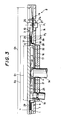
- the circular centre plate 2 is so formed by means of press work as to have a cylindrical portion 28 standing on the outer edge thereof and a flange portion 29 externally extending from the cylindrical portion 28 as shown in Figure 3.
- the outer periphery of the cylindrical portion 28 is fitted into a round hole 30 provided in the centre portion of the magnetic sheet 3 so as to make the centre of the magnetic sheet 3 coincide with the centre of the circular centre plate 2, and then the portion 3a around the round hole 30 of the magnetic sheet 3 is stuck to the lower face of the flange portion 29 with an adhesive 31.
- a ring-like locating rib 32 having a large diameter D1 is integrally formed with the upper half 6 in the centre portion of the inner face thereof as shown in Figure 3 and is placed within the inner periphery of the cylindrical portion 28 of the circular centre plate 2 so as to position the magnetic sheet 3 in the cartridge 8, otherwise the magnetic sheet 3 could horizontally move over a predetermined extent in the cartridge 8 and, as a result, the edge of the magnetic sheet 3 could come in contact with the wall of the cartridge 8 and be broken.
- the top of the centre pin 22 of the turntable 15 abuts against the slippery sheet 33 which is stuck to the inner face of the upper half 6 as shown in Figure 3.
- the locating rib 32 having a relatively large diameter D1 and integrally formed with the upper half 6 is inserted within the inner periphery of the cylindrical portion 28 of the circular centre plate 2 so as to position the magnetic sheet 3 in the cartridge 8, so that it is difficult to change the diameter D2 of the circular centre plate 2 below a predetermined value.
- the diameter D2 of the circular centre plate 2 still remains large in relation to the diameter D3 of the magnetic sheet 3.
- a recording medium such as a magnetic sheet or the lile
- Another object of the invention is to provide a disk cartridge best suited for high density recording, such as for example, for a micro floppy disk having a capacity of two mega bytes.
- Still another object of the invention is to provide a disk cartridge in which the diameter of the circular centre plate can be made small while securing the stability of the circular centre plate on a turntable and providing a sufficiently large contact area to allow sticking of the sheet-like recording medium fast to a flange portion of the circular centre plate.
- a disk cartridge of the type including a sheet-like recording medium fixed to the periphery of a circular centre plate in which a centre hole and an eccentric hole are provided, the sheet-like recording medium being rotatably accommodated in a cartridge comprising an upper half and a lower half, and the circular centre plate being loosely fitted in a turntable insertion hole provided in the lower half, wherein a ring having a small diameter is formed integrally and coaxially with said circular centre plate on the upper side thereof to surround said centre hole, and said ring is loosely fitted in a locating rib having a small diameter and formed integrally with said upper half on the inside thereof so as to position said recording medium in said cartridge on the central part of said circular centre plate.
- the positioning of the recording medium in the cartridge is obtained by restricting the movement of the circular centre plate not on the peripheral side thereof, but in its central part.
- Said ring having a small diameter can be made of synthetic resin, and formed by outsert molding to be stuck very fast to the circular centre plate.
- Disk 1 has a circular centre plate 36 made of metal, such as stainless steel or the like.
- a ring 37 having a small diameter D4 and made of synthetic resin, such as ABS resin or the like is formed integrally by outsert moulding with a wall of the circular centre plate 36 projecting upwards from the outer surface thereof, and forming a centre hole 4 of almost square shape, the ring 37 being provided coaxially with the centre hole 4.
- a joining portion 46 such as a hole or a recess is provided to allow the ring 37 to stick to the circular centre plate 36 as firmly as possible.
- a flange 38 made of synthetic resin, such as ABS resin or the like is so formed integrally by outsert moulding with the circular centre plate 36 on the outer edge thereof as to project upwards from the circular centre plate 36 and extend horizontally.
- the flange 38 has a cylindrical portion 38a which projects upwardly therefrom on the fixed end thereof and is inserted into a circular hole 40 provided in the centre portion of a sheet-like recording medium, such as a magnetic sheet 39 having a diameter of 3.5 inches, so as to make the centre of the magnetic sheet 39 coincide with the center of the circular centre plate 36.
- a portion 39a of the magnetic sheet 39 around the hole 40 is secured to the upper face of the flange 38 by means of an adhesive 41 or the like.
- the disk 1 is rotatably accommodated in a cartridge 44 comprising an upper half 42 and a lower half 43 and made of synthetic resin.
- the circular centre plate 36 is loosely fitted in a turntable insertion hole 9 provided in the lower half 43.
- a cylindrical locating rib 45 having a small inside diameter D5 larger than D4 is integrally formed with the upper half 42 in the centre portion of the inner face thereof.
- the ring 37 having a small diameter D4 and secured to the circular centre plate 36 in the vicinity of the centre thereof is located within the inner periphery of the locating rib 45 having a small inside diameter D5 so as to have the magnetic sheet 39 positioned in the cartridge 44.
- the diameter of the locating rib 45 is determined so that the locating rib 45 does not interfere with the driving pin 23 of the turntable 15, and, also, the inside diameter of the flange 38 is determined so that the flange 38 does not interfere with the eccentric hole of the circular centre plate 36.
- D6 l2 shown in Figure 4 and D2,l1 shown in Figure 3 it appears that D2 is larger than D6, so that l2 is larger than l1 by the difference between D2 and D6.
- the contact condition of the magnetic sheet 39 with the magnetic heads 26 and 27 is much improved even when a height difference H1 arises between the lower face 39b of the portion 39a around the round hole 40 of the magnetic sheet 39 and the upper face 27a of the lower magnetic head 27, acting as a standard to determine the height of the magnetic sheet 39, due to, for example, a fluctuation of the thickness of the adhesive layer, through which the portion 39a around the round hole 40 is stuck to the upper face of the flange 38 of the circular centre plate 36.
- troubles such as the aberration of tracking, spacing loss or the like are not encountered.
- Figures 6 and 7 show other embodiments concerning the portion of the circular centre plate to which the magnetic sheet is fixed.
- a circular plate 50 is shown which is similar in appearance to the circular centre plate 36 shown in Figure 5.
- the circular centre plate 50 has a cylindrical portion 51 with a smaller diameter D10, but has a flange portion 52 with a width w which is the same as in the preceding embodiment to allow a magnetic sheet 49 to be stuck fast to the circular centre plate 50 by the help of an adhesive 53.
- the stability of the circular centre plate 50 on the turntable 15 could be effected as the diameter D10 of the cylindrical portion 51 is made small.
- the diameter of a cylindrical portion 56 of a circular centre plate 55 is not decreased. Instead, the width w of a flange portion 57 of the circular centre plate 55 is decreased so as to make the diameter of the circular centre plate 55 smaller.
- a ring 58 made of synthetic resin and having a stuck portion 61 of a width s is formed integrally by outsert moulding with the circular centre plate 55 on the inner periphery of the cylindrical portion 56 thereof.
- the ring 37 is not necessarily formed by outsert moulding as in the above described embodiments. It can be secured to the circular centre plate 36 by means of adhesion, weld, screws or the like. Further, the sheet-like recording medium can be other than a magnetic sheet.
- this invention can be applied not only to disk cartridges including micro floppy disks but also to disk cartridges including recording mediums which are used under various types of recording or reproducing.
Landscapes
- Packaging For Recording Disks (AREA)
- Holding Or Fastening Of Disk On Rotational Shaft (AREA)
- Magnetic Record Carriers (AREA)
- Liquid Crystal (AREA)
- Rotational Drive Of Disk (AREA)
Abstract
Description
- This invention relates to a disk cartridge comprising a cartridge and a sheet-like recording medium which is rotatably accommodated in the cartridge and fixed to the periphery of a circular centre plate, and the invention is best suited for applying to a disk cartridge including a micro floppy disk, for example, comprising a magnetic sheet having a diameter of 3.5 inches.
- Figures 1 to 3 show a conventional disk cartridge including a micro floppy disk and a driving device for rotating the micro floppy disk.
- As illustrated in Figures 1 and 2, a floppy disk 1 (simply described as "disk" hereafter) comprises a
circular centre plate 2 of stainless steel or the like and amagnetic sheet 3, namely, a sheet-like recording medium having a diameter of 3.5 inches and fixed to the periphery of thecircular centre plate 2. An almostsquare centre hole 4 and an almost rectangulareccentric hole 5, which is arranged aslant of thecentre hole 4 at a predetermined angle, are provided in thecentre plate 2. - The
disk 1 is rotatably accommodated in acartridge 8 comprising anupper half 6 and alower half 7 which are made of synthetic resin, and thecircular centre plate 2 is loosely fitted in aturntable insertion hole 9 which is provided in the centre portion of thelower half 7. A pair of upper and lowerhead insertion holes 10 provided in the respective upper andlower halves magnetic sheet 3 are openable and closable by the use ofshutters 11. - The driving device is disposed in a disk player (not shown) and comprises a
turntable 15 which is so fixed to the upper end portion of theshaft 14 of amotor 13 as to be horizontally rotated. Amagnetic chuck 18 comprising ayoke 16 and amagnetic plate 17 is secured to the upper side of theturntable 15 withscrews 20 through aspacer 19, and a thinslippery sheet 21 of non magnetic material is stuck in the centre portion of the upper face of themagnetic chuck 18. Furthermore, acentre pin 22, namely, the distal end of themotor shaft 14, projects upwards from themagnetic chuck 18 in the centre portion thereof, and a drivingpin 23 is provided apart from the centre of themagnetic chuck 18. The drivingpin 23 is secured to aleaf spring 24 sandwiched in between themagnetic plate 17 and thespacer 19, and projects upwards from themagnetic chuck 18 through a throughhole 25 thereof. - As shown in Figure 1, when the
cartridge 8 is horizontally mounted on theturntable 15 under a state that theshutter 11 is opened, themagnetic chuck 18 is inserted in theturntable insertion hole 9 as shown in Figure 2, and thecircular centre plate 2 of thedisk 1 is attracted by the magnetic force generated by themagnetic chuck 18 and horizontally located on theslippery sheet 21. Simultaneously, thecentre pin 22 and the drivingpin 23 of theturntable 15 are fitted into thecircular centre hole 4 and theeccentric hole 5 of thecircular centre plate 2, respectively. As shown in Figure 3, a pair of upper and lowermagnetic heads respective insertion holes 10 and come in contact with the upper and lower faces of themagnetic sheet 3 of thedisk 1, respectively. - When the
motor 13 is started after thedisk 1 is loaded and theturntable 15 is rotated, thecircular centre plate 2 is positioned by the help of thecentre pin 22 and the torque for rotating thecircular centre plate 2 is transmitted through thedriving pin 23, so that themagnetic sheet 3 is horizontally rotated in thecartridge 8. Therefore, when themagnetic heads magnetic sheet 3, recording or reproducing is selectively performed on one of the two faces of themagnetic sheet 3. - Meanwhile, the
circular centre plate 2 is so formed by means of press work as to have acylindrical portion 28 standing on the outer edge thereof and aflange portion 29 externally extending from thecylindrical portion 28 as shown in Figure 3. The outer periphery of thecylindrical portion 28 is fitted into around hole 30 provided in the centre portion of themagnetic sheet 3 so as to make the centre of themagnetic sheet 3 coincide with the centre of thecircular centre plate 2, and then the portion 3a around theround hole 30 of themagnetic sheet 3 is stuck to the lower face of theflange portion 29 with an adhesive 31. - Furthermore, a ring-like locating
rib 32 having a large diameter D₁ is integrally formed with theupper half 6 in the centre portion of the inner face thereof as shown in Figure 3 and is placed within the inner periphery of thecylindrical portion 28 of thecircular centre plate 2 so as to position themagnetic sheet 3 in thecartridge 8, otherwise themagnetic sheet 3 could horizontally move over a predetermined extent in thecartridge 8 and, as a result, the edge of themagnetic sheet 3 could come in contact with the wall of thecartridge 8 and be broken. The top of thecentre pin 22 of theturntable 15 abuts against theslippery sheet 33 which is stuck to the inner face of theupper half 6 as shown in Figure 3. - However, due to fluctuations in thickness of the layer formed by the
adhesive 31, with which the portion 3a around theround hole 30 of themagnetic sheet 3 is stuck on the lower face of theflange portion 29 of thecircular centre plate 2 as shown in Figure 3, or for other reasons, a height difference H₁ arises between thelower face 3b of the portion 3a around theround hole 30 and theupper face 27a of the lowermagnetic head 27, which functions as a standard to determine the height of themagnetic sheet 3. Thus, the horizontalupper face 27a of the lowermagnetic head 27 cannot whooly come into contact with themagnetic sheet 3, and a deflection is generated in the radius direction of themagnetic sheet 3, resulting in making bad contacts between themagnetic heads magnetic sheet 3. Such bad contacts particularly occur when themagnetic heads magnetic heads circular centre plate 2 for recording or reproducing. - That is, the portion 3a around the
round hole 30 of themagnetic sheet 3 being fixed with theadhesive 31 to the lower face of theflange portion 29 of thecircular centre plate 2, it becomes more difficult to have themagnetic sheet 3 deflected, as themagnetic head flange portion 29 of thecircular centre plate 2 and the contact condition between themagnetic heads magnetic sheet 3 becomes worse, when themagnetic heads - Therefore, if the diameter D₂ of the
circular centre plate 2 can be made much smaller than the diameter D₃ (= 3.5 inches) of themagnetic sheet 3, the above contacts are improved, because the distance l₁ between the position P₁ in which themagnetic heads flange portion 29 and a position P₂ which coincides with the outer edge of the portion 3a of thesheet 3 fixed by theadhesive 31 around theround hole 30, is made large enough. But, to make the diameter D₂ small is not simple. - That is, in a conventional disk, the locating
rib 32 having a relatively large diameter D₁ and integrally formed with theupper half 6 is inserted within the inner periphery of thecylindrical portion 28 of thecircular centre plate 2 so as to position themagnetic sheet 3 in thecartridge 8, so that it is difficult to change the diameter D₂ of thecircular centre plate 2 below a predetermined value. Thus, the diameter D₂ of thecircular centre plate 2 still remains large in relation to the diameter D₃ of themagnetic sheet 3. - Accordingly, it is an object of the present invention to provide a disk cartridge in which the diameter of a circular centre plate can be made small in relation to the diameter of a recording medium, such as a magnetic sheet or the lile, to avoid troubles such as aberrations of tracking, spacing losses and the like due to defective contacts of recording and/or reproducing heads, such as magnetic heads or the like with the recording medium at the time of recording or reproducing.
- Another object of the invention is to provide a disk cartridge best suited for high density recording, such as for example, for a micro floppy disk having a capacity of two mega bytes.
- Still another object of the invention is to provide a disk cartridge in which the diameter of the circular centre plate can be made small while securing the stability of the circular centre plate on a turntable and providing a sufficiently large contact area to allow sticking of the sheet-like recording medium fast to a flange portion of the circular centre plate.
- The above and other objects are attained by a disk cartridge of the type including a sheet-like recording medium fixed to the periphery of a circular centre plate in which a centre hole and an eccentric hole are provided, the sheet-like recording medium being rotatably accommodated in a cartridge comprising an upper half and a lower half, and the circular centre plate being loosely fitted in a turntable insertion hole provided in the lower half, wherein a ring having a small diameter is formed integrally and coaxially with said circular centre plate on the upper side thereof to surround said centre hole, and said ring is loosely fitted in a locating rib having a small diameter and formed integrally with said upper half on the inside thereof so as to position said recording medium in said cartridge on the central part of said circular centre plate.
- Thus, the positioning of the recording medium in the cartridge is obtained by restricting the movement of the circular centre plate not on the peripheral side thereof, but in its central part.
- Said ring having a small diameter can be made of synthetic resin, and formed by outsert molding to be stuck very fast to the circular centre plate.
- The invention will be more readily understood from the reading of the following description made with reference to the accompanying drawings wherein:
- Figure 1 is a perspective view of a conventional disk cartridge;
- Figure 2 is a sectional side view of the principal portion of the disk cartridge of Figure 1;
- Figure 3 is a sectional view of the principal portion of the disk cartridge of Figure 1 on an enlarged scale;
- Figure 4 is a sectional side view of a disk cartridge on an enlarged scale according to an embodiment of this invention;
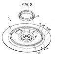
- Figure 5 is a perspective view of the principal portion of the disk cartridge of Figure 4;
- Figure 6 is a sectional side view of a disk cartridge according to a second embodiment of this invention; and
- Figure 7 is a sectional side view of a disk cartridge according to a third embodiment of this invention.
- Firstly, a first embodiment of this invention applied to a disk cartridge including a micro floppy disk will be described hereinafter by reference to Figures 4 and 5. In all the drawings, same or similar parts are denoted by the same reference numerals.
-
Disk 1 has acircular centre plate 36 made of metal, such as stainless steel or the like. Aring 37 having a small diameter D₄ and made of synthetic resin, such as ABS resin or the like is formed integrally by outsert moulding with a wall of thecircular centre plate 36 projecting upwards from the outer surface thereof, and forming acentre hole 4 of almost square shape, thering 37 being provided coaxially with thecentre hole 4. In the wall of thecircular centre plate 36, a joiningportion 46, such as a hole or a recess is provided to allow thering 37 to stick to thecircular centre plate 36 as firmly as possible. - A
flange 38 made of synthetic resin, such as ABS resin or the like is so formed integrally by outsert moulding with thecircular centre plate 36 on the outer edge thereof as to project upwards from thecircular centre plate 36 and extend horizontally. Theflange 38 has acylindrical portion 38a which projects upwardly therefrom on the fixed end thereof and is inserted into acircular hole 40 provided in the centre portion of a sheet-like recording medium, such as amagnetic sheet 39 having a diameter of 3.5 inches, so as to make the centre of themagnetic sheet 39 coincide with the center of thecircular centre plate 36. Aportion 39a of themagnetic sheet 39 around thehole 40 is secured to the upper face of theflange 38 by means of anadhesive 41 or the like. - The
disk 1 is rotatably accommodated in acartridge 44 comprising anupper half 42 and alower half 43 and made of synthetic resin. Thecircular centre plate 36 is loosely fitted in aturntable insertion hole 9 provided in thelower half 43. A cylindrical locatingrib 45 having a small inside diameter D₅ larger than D₄ is integrally formed with theupper half 42 in the centre portion of the inner face thereof. Thering 37 having a small diameter D₄ and secured to thecircular centre plate 36 in the vicinity of the centre thereof is located within the inner periphery of the locatingrib 45 having a small inside diameter D₅ so as to have themagnetic sheet 39 positioned in thecartridge 44. Of course, the diameter of the locatingrib 45 is determined so that the locatingrib 45 does not interfere with the drivingpin 23 of theturntable 15, and, also, the inside diameter of theflange 38 is determined so that theflange 38 does not interfere with the eccentric hole of thecircular centre plate 36. - As shown in Figure 4, the diameter D₆ of the
flange 38 can be made small enough in relation to the diameter D₃ (= 3.5 inches) of themagnetic sheet 39 to obtain a relatively large distance l₂ between the outer edge P₃ of theportion 39a of the magnetic sheet fixed on the upper face of theflange 38 around thehole 40 and the position P₁ (the same as hereinbefore defined), where themagnetic heads circular centre plate 36 for recording or reproducing. In other words, comparing D₆, l₂ shown in Figure 4, and D₂,l₁ shown in Figure 3, it appears that D₂ is larger than D₆, so that l₂ is larger than l₁ by the difference between D₂ and D₆. - According to this invention, and because the distance P₂ is made large enough, the contact condition of the
magnetic sheet 39 with themagnetic heads lower face 39b of theportion 39a around theround hole 40 of themagnetic sheet 39 and theupper face 27a of the lowermagnetic head 27, acting as a standard to determine the height of themagnetic sheet 39, due to, for example, a fluctuation of the thickness of the adhesive layer, through which theportion 39a around theround hole 40 is stuck to the upper face of theflange 38 of thecircular centre plate 36. Thus, troubles such as the aberration of tracking, spacing loss or the like are not encountered. - Figures 6 and 7 show other embodiments concerning the portion of the circular centre plate to which the magnetic sheet is fixed. In Figure 6, a
circular plate 50 is shown which is similar in appearance to thecircular centre plate 36 shown in Figure 5. Thecircular centre plate 50 has acylindrical portion 51 with a smaller diameter D₁₀, but has aflange portion 52 with a width w which is the same as in the preceding embodiment to allow amagnetic sheet 49 to be stuck fast to thecircular centre plate 50 by the help of an adhesive 53. But the stability of thecircular centre plate 50 on theturntable 15 could be effected as the diameter D₁₀ of thecylindrical portion 51 is made small. Hence, aring 54 made of synthetic resin and having a width n and a diameter D₁₁, is formed on the periphery of thecylindrical portion 51 by outsert moulding, so as to improve the stability of thecircular centre plate 50 on theturntable 15. - In Figure 7, the diameter of a
cylindrical portion 56 of acircular centre plate 55 is not decreased. Instead, the width w of aflange portion 57 of thecircular centre plate 55 is decreased so as to make the diameter of thecircular centre plate 55 smaller. However, due to the narrow width w of theflange portion 57, the contact area between themagnetic sheet 60 and the flange portion is too small to make themagnetic sheet 60 stick fast to thecircular centre plate 55. Therefore, aring 58 made of synthetic resin and having a stuckportion 61 of a width s is formed integrally by outsert moulding with thecircular centre plate 55 on the inner periphery of thecylindrical portion 56 thereof. Thus, themagnetic sheet 60 is stuck over a width r (= w + s) by the help of an adhesive 59, so that themagnetic sheet 60 is steadily integral with thecircular centre plate 55. - It should be noted that the
ring 37 is not necessarily formed by outsert moulding as in the above described embodiments. It can be secured to thecircular centre plate 36 by means of adhesion, weld, screws or the like. Further, the sheet-like recording medium can be other than a magnetic sheet. - In addition, this invention can be applied not only to disk cartridges including micro floppy disks but also to disk cartridges including recording mediums which are used under various types of recording or reproducing.
Claims (3)
Applications Claiming Priority (2)
| Application Number | Priority Date | Filing Date | Title |
|---|---|---|---|
| JP211976/85 | 1985-09-25 | ||
| JP60211976A JPH0634323B2 (en) | 1985-09-25 | 1985-09-25 | Disco Cartridge |
Publications (3)
| Publication Number | Publication Date |
|---|---|
| EP0216708A2 true EP0216708A2 (en) | 1987-04-01 |
| EP0216708A3 EP0216708A3 (en) | 1988-09-21 |
| EP0216708B1 EP0216708B1 (en) | 1992-04-01 |
Family
ID=16614823
Family Applications (1)
| Application Number | Title | Priority Date | Filing Date |
|---|---|---|---|
| EP86402089A Expired - Lifetime EP0216708B1 (en) | 1985-09-25 | 1986-09-24 | Disk cartridge |
Country Status (9)
| Country | Link |
|---|---|
| US (1) | US4812937A (en) |
| EP (1) | EP0216708B1 (en) |
| JP (1) | JPH0634323B2 (en) |
| AT (1) | ATE74462T1 (en) |
| AU (1) | AU593579B2 (en) |
| CA (1) | CA1284380C (en) |
| DE (1) | DE3684651D1 (en) |
| HK (1) | HK101695A (en) |
| SG (1) | SG30549G (en) |
Cited By (5)
| Publication number | Priority date | Publication date | Assignee | Title |
|---|---|---|---|---|
| EP0526222A3 (en) * | 1991-07-31 | 1994-01-05 | Sony Corp | |
| US5315470A (en) * | 1991-04-25 | 1994-05-24 | Sony Corporation | Disk cartridge with centered magnetic plate |
| EP0566032A3 (en) * | 1992-04-13 | 1994-08-24 | Matsushita Electric Industrial Co Ltd | Hub type optical disk and injection molding die for molding its disk substrate |
| EP0974970A4 (en) * | 1997-11-14 | 2000-01-26 | Sony Corp | DISC CARTRIDGE |
| KR100272813B1 (en) * | 1991-07-31 | 2000-11-15 | 이데이 노부유끼 | Disc cartridge |
Families Citing this family (8)
| Publication number | Priority date | Publication date | Assignee | Title |
|---|---|---|---|---|
| JPH064466Y2 (en) * | 1989-03-07 | 1994-02-02 | 花王株式会社 | Magnetic disk cartridge |
| DE69232492T2 (en) * | 1991-12-07 | 2002-11-28 | Minebea K.K., Nagano | Motor for starting a plate |
| US5815344A (en) * | 1992-02-17 | 1998-09-29 | Sony Corporation | Disc cartridge loading apparatus |
| US5437404A (en) * | 1993-07-13 | 1995-08-01 | Illinois Tool Works Inc. | Adjustable shear block assembly |
| JPH08308197A (en) * | 1995-05-08 | 1996-11-22 | Matsushita Electric Ind Co Ltd | Spindle motor |
| JPH097333A (en) * | 1995-06-23 | 1997-01-10 | Fuji Photo Film Co Ltd | Magnetic disk cartridge |
| JPH09147513A (en) * | 1995-11-22 | 1997-06-06 | Sony Corp | Disk cartridge |
| JP2001035115A (en) * | 1999-07-22 | 2001-02-09 | Fuji Photo Film Co Ltd | Center core for magnetic disk |
Family Cites Families (10)
| Publication number | Priority date | Publication date | Assignee | Title |
|---|---|---|---|---|
| US4194228A (en) * | 1978-10-11 | 1980-03-18 | Magnetic Peripherals Inc. | Magnetic disc housing with means to prevent radial disc shift |
| JPS56137555A (en) * | 1980-03-27 | 1981-10-27 | Sony Corp | Optical disc cassette and disc driving method |
| JPS606938Y2 (en) * | 1980-08-14 | 1985-03-07 | ソニー株式会社 | Disc cassette for recording and playback |
| JPS6245356Y2 (en) * | 1981-06-05 | 1987-12-03 | ||
| JPS5950034U (en) * | 1982-09-21 | 1984-04-03 | ソニー株式会社 | Information record sheet |
| JPS6035385A (en) * | 1983-08-03 | 1985-02-23 | Hitachi Maxell Ltd | Disk cartridge |
| US4586102A (en) * | 1983-08-04 | 1986-04-29 | Eastman Kodak Company | Track number indicator |
| US4571718A (en) * | 1984-07-11 | 1986-02-18 | Eastman Kodak Company | Optical disk cartridge and cooperating apparatus |
| NL8402602A (en) * | 1984-08-27 | 1986-03-17 | Philips Nv | DISC CASSETTE. |
| JPS61129721A (en) * | 1984-11-27 | 1986-06-17 | Nagaoka:Kk | Head cleaning device |
-
1985
- 1985-09-25 JP JP60211976A patent/JPH0634323B2/en not_active Expired - Fee Related
-
1986
- 1986-09-18 CA CA000518493A patent/CA1284380C/en not_active Expired - Lifetime
- 1986-09-24 AT AT86402089T patent/ATE74462T1/en not_active IP Right Cessation
- 1986-09-24 EP EP86402089A patent/EP0216708B1/en not_active Expired - Lifetime
- 1986-09-24 SG SG1995903779A patent/SG30549G/en unknown
- 1986-09-24 DE DE8686402089T patent/DE3684651D1/en not_active Expired - Lifetime
- 1986-09-24 AU AU63092/86A patent/AU593579B2/en not_active Ceased
-
1988
- 1988-06-23 US US07/212,025 patent/US4812937A/en not_active Expired - Lifetime
-
1995
- 1995-06-22 HK HK101695A patent/HK101695A/en not_active IP Right Cessation
Cited By (10)
| Publication number | Priority date | Publication date | Assignee | Title |
|---|---|---|---|---|
| US5315470A (en) * | 1991-04-25 | 1994-05-24 | Sony Corporation | Disk cartridge with centered magnetic plate |
| EP0526222A3 (en) * | 1991-07-31 | 1994-01-05 | Sony Corp | |
| US5323382A (en) * | 1991-07-31 | 1994-06-21 | Sony Corporation | Disc cartridge |
| AU662745B2 (en) * | 1991-07-31 | 1995-09-14 | Sony Corporation | Disc cartridge |
| AU671404B2 (en) * | 1991-07-31 | 1996-08-22 | Sony Corporation | Disc cartridge |
| EP0736873A3 (en) * | 1991-07-31 | 1996-11-13 | Sony Corporation | Disc cartridge |
| AU677516B2 (en) * | 1991-07-31 | 1997-04-24 | Sony Corporation | Disc cartridge |
| KR100272813B1 (en) * | 1991-07-31 | 2000-11-15 | 이데이 노부유끼 | Disc cartridge |
| EP0566032A3 (en) * | 1992-04-13 | 1994-08-24 | Matsushita Electric Industrial Co Ltd | Hub type optical disk and injection molding die for molding its disk substrate |
| EP0974970A4 (en) * | 1997-11-14 | 2000-01-26 | Sony Corp | DISC CARTRIDGE |
Also Published As
| Publication number | Publication date |
|---|---|
| SG30549G (en) | 1995-09-18 |
| DE3684651D1 (en) | 1992-05-07 |
| ATE74462T1 (en) | 1992-04-15 |
| EP0216708B1 (en) | 1992-04-01 |
| JPH0634323B2 (en) | 1994-05-02 |
| EP0216708A3 (en) | 1988-09-21 |
| US4812937A (en) | 1989-03-14 |
| AU593579B2 (en) | 1990-02-15 |
| CA1284380C (en) | 1991-05-21 |
| HK101695A (en) | 1995-06-30 |
| AU6309286A (en) | 1987-03-26 |
| JPS6273477A (en) | 1987-04-04 |
Similar Documents
| Publication | Publication Date | Title |
|---|---|---|
| CA1190319A (en) | Flexible magnetic disk cassette and a recording and/or reproducing apparatus for the same | |
| EP0216708B1 (en) | Disk cartridge | |
| US4590532A (en) | Magnetic disk assembly cartridge for same and recording/reproducing apparatus for use with same | |
| AU603703B2 (en) | Flexible disk cassette | |
| US4002826A (en) | Playback apparatus, in particular, video player, for playing round records provided with information tracks | |
| EP0116471B1 (en) | Flexible magnetic discs | |
| US4831478A (en) | Disc drive assembly for supporting a recording disc | |
| EP0352918A2 (en) | A disk cartridge | |
| US5587994A (en) | Cartridge used for a disc-shaped recording medium | |
| JPS649660B2 (en) | ||
| JPS637981Y2 (en) | ||
| US4983439A (en) | Method of manufacturing a recording medium and recording medium | |
| EP0246298B1 (en) | A storage disk drive mechanism and hub member | |
| EP0283921A2 (en) | Disk drive device | |
| JPH0333983Y2 (en) | ||
| KR960004071B1 (en) | Disc cartridge | |
| JPS6325551Y2 (en) | ||
| JPH0341916B2 (en) | ||
| JPH0521757Y2 (en) | ||
| CA1219071A (en) | Flexible disc recording and/or reproducing apparatus | |
| JPS60164975A (en) | Disk cartridge | |
| JPS62114178A (en) | Cassette disk | |
| JPH0574026A (en) | Disk | |
| JPS6288189A (en) | Flexible magnetic disk | |
| JPH09245453A (en) | Disk cartridge |
Legal Events
| Date | Code | Title | Description |
|---|---|---|---|
| PUAI | Public reference made under article 153(3) epc to a published international application that has entered the european phase |
Free format text: ORIGINAL CODE: 0009012 |
|
| AK | Designated contracting states |
Kind code of ref document: A2 Designated state(s): AT DE FR GB NL |
|
| PUAL | Search report despatched |
Free format text: ORIGINAL CODE: 0009013 |
|
| AK | Designated contracting states |
Kind code of ref document: A3 Designated state(s): AT DE FR GB NL |
|
| 17P | Request for examination filed |
Effective date: 19890320 |
|
| 17Q | First examination report despatched |
Effective date: 19900808 |
|
| GRAA | (expected) grant |
Free format text: ORIGINAL CODE: 0009210 |
|
| AK | Designated contracting states |
Kind code of ref document: B1 Designated state(s): AT DE FR GB NL |
|
| REF | Corresponds to: |
Ref document number: 74462 Country of ref document: AT Date of ref document: 19920415 Kind code of ref document: T |
|
| REF | Corresponds to: |
Ref document number: 3684651 Country of ref document: DE Date of ref document: 19920507 |
|
| ET | Fr: translation filed | ||
| PLBE | No opposition filed within time limit |
Free format text: ORIGINAL CODE: 0009261 |
|
| STAA | Information on the status of an ep patent application or granted ep patent |
Free format text: STATUS: NO OPPOSITION FILED WITHIN TIME LIMIT |
|
| 26N | No opposition filed | ||
| PGFP | Annual fee paid to national office [announced via postgrant information from national office to epo] |
Ref country code: GB Payment date: 19960916 Year of fee payment: 11 |
|
| PGFP | Annual fee paid to national office [announced via postgrant information from national office to epo] |
Ref country code: AT Payment date: 19960924 Year of fee payment: 11 |
|
| PGFP | Annual fee paid to national office [announced via postgrant information from national office to epo] |
Ref country code: NL Payment date: 19960930 Year of fee payment: 11 |
|
| PG25 | Lapsed in a contracting state [announced via postgrant information from national office to epo] |
Ref country code: GB Free format text: LAPSE BECAUSE OF NON-PAYMENT OF DUE FEES Effective date: 19970924 Ref country code: AT Free format text: LAPSE BECAUSE OF NON-PAYMENT OF DUE FEES Effective date: 19970924 |
|
| PG25 | Lapsed in a contracting state [announced via postgrant information from national office to epo] |
Ref country code: NL Free format text: LAPSE BECAUSE OF NON-PAYMENT OF DUE FEES Effective date: 19980401 |
|
| GBPC | Gb: european patent ceased through non-payment of renewal fee |
Effective date: 19970924 |
|
| NLV4 | Nl: lapsed or anulled due to non-payment of the annual fee |
Effective date: 19980401 |
|
| PGFP | Annual fee paid to national office [announced via postgrant information from national office to epo] |
Ref country code: FR Payment date: 20020910 Year of fee payment: 17 |
|
| PGFP | Annual fee paid to national office [announced via postgrant information from national office to epo] |
Ref country code: DE Payment date: 20021002 Year of fee payment: 17 |
|
| PG25 | Lapsed in a contracting state [announced via postgrant information from national office to epo] |
Ref country code: DE Free format text: LAPSE BECAUSE OF NON-PAYMENT OF DUE FEES Effective date: 20040401 |
|
| PG25 | Lapsed in a contracting state [announced via postgrant information from national office to epo] |
Ref country code: FR Free format text: LAPSE BECAUSE OF NON-PAYMENT OF DUE FEES Effective date: 20040528 |
|
| REG | Reference to a national code |
Ref country code: FR Ref legal event code: ST |