EP0216794B1 - Dispositif de positionnement de calotte cotyloide - Google Patents
Dispositif de positionnement de calotte cotyloide Download PDFInfo
- Publication number
- EP0216794B1 EP0216794B1 EP86900990A EP86900990A EP0216794B1 EP 0216794 B1 EP0216794 B1 EP 0216794B1 EP 86900990 A EP86900990 A EP 86900990A EP 86900990 A EP86900990 A EP 86900990A EP 0216794 B1 EP0216794 B1 EP 0216794B1
- Authority
- EP
- European Patent Office
- Prior art keywords
- pusher
- flange
- arm
- ball
- acetabular cup
- Prior art date
- Legal status (The legal status is an assumption and is not a legal conclusion. Google has not performed a legal analysis and makes no representation as to the accuracy of the status listed.)
- Expired
Links
- 210000000588 acetabulum Anatomy 0.000 claims abstract description 16
- 230000013011 mating Effects 0.000 claims 1
- 238000001356 surgical procedure Methods 0.000 abstract description 10
- 238000011541 total hip replacement Methods 0.000 abstract description 5
- 239000004568 cement Substances 0.000 description 15
- 210000001624 hip Anatomy 0.000 description 5
- 239000002639 bone cement Substances 0.000 description 2
- 210000004394 hip joint Anatomy 0.000 description 2
- 238000006116 polymerization reaction Methods 0.000 description 2
- 229920002379 silicone rubber Polymers 0.000 description 2
- 239000004945 silicone rubber Substances 0.000 description 2
- 239000010963 304 stainless steel Substances 0.000 description 1
- 235000003625 Acrocomia mexicana Nutrition 0.000 description 1
- 244000202285 Acrocomia mexicana Species 0.000 description 1
- 101000911772 Homo sapiens Hsc70-interacting protein Proteins 0.000 description 1
- 229910000589 SAE 304 stainless steel Inorganic materials 0.000 description 1
- 210000000988 bone and bone Anatomy 0.000 description 1
- 239000003795 chemical substances by application Substances 0.000 description 1
- 230000000295 complement effect Effects 0.000 description 1
- 230000003247 decreasing effect Effects 0.000 description 1
- 230000001419 dependent effect Effects 0.000 description 1
- 201000010099 disease Diseases 0.000 description 1
- 208000037265 diseases, disorders, signs and symptoms Diseases 0.000 description 1
- 229920001971 elastomer Polymers 0.000 description 1
- 239000000806 elastomer Substances 0.000 description 1
- 238000011540 hip replacement Methods 0.000 description 1
- 238000002513 implantation Methods 0.000 description 1
- 208000014674 injury Diseases 0.000 description 1
- 238000003780 insertion Methods 0.000 description 1
- 230000037431 insertion Effects 0.000 description 1
- 238000004519 manufacturing process Methods 0.000 description 1
- 239000000463 material Substances 0.000 description 1
- 238000012986 modification Methods 0.000 description 1
- 230000004048 modification Effects 0.000 description 1
- 230000000399 orthopedic effect Effects 0.000 description 1
- 229920003229 poly(methyl methacrylate) Polymers 0.000 description 1
- 239000004926 polymethyl methacrylate Substances 0.000 description 1
- 229920001296 polysiloxane Polymers 0.000 description 1
- 230000000284 resting effect Effects 0.000 description 1
- 239000011435 rock Substances 0.000 description 1
- 230000009528 severe injury Effects 0.000 description 1
- 238000006467 substitution reaction Methods 0.000 description 1
- 230000008733 trauma Effects 0.000 description 1
- 238000012800 visualization Methods 0.000 description 1
Images

Classifications
-
- A—HUMAN NECESSITIES
- A61—MEDICAL OR VETERINARY SCIENCE; HYGIENE
- A61F—FILTERS IMPLANTABLE INTO BLOOD VESSELS; PROSTHESES; DEVICES PROVIDING PATENCY TO, OR PREVENTING COLLAPSING OF, TUBULAR STRUCTURES OF THE BODY, e.g. STENTS; ORTHOPAEDIC, NURSING OR CONTRACEPTIVE DEVICES; FOMENTATION; TREATMENT OR PROTECTION OF EYES OR EARS; BANDAGES, DRESSINGS OR ABSORBENT PADS; FIRST-AID KITS
- A61F2/00—Filters implantable into blood vessels; Prostheses, i.e. artificial substitutes or replacements for parts of the body; Appliances for connecting them with the body; Devices providing patency to, or preventing collapsing of, tubular structures of the body, e.g. stents
- A61F2/02—Prostheses implantable into the body
- A61F2/30—Joints
- A61F2/46—Special tools for implanting artificial joints
- A61F2/4603—Special tools for implanting artificial joints for insertion or extraction of endoprosthetic joints or of accessories thereof
- A61F2/4609—Special tools for implanting artificial joints for insertion or extraction of endoprosthetic joints or of accessories thereof of acetabular cups
-
- A—HUMAN NECESSITIES
- A61—MEDICAL OR VETERINARY SCIENCE; HYGIENE
- A61F—FILTERS IMPLANTABLE INTO BLOOD VESSELS; PROSTHESES; DEVICES PROVIDING PATENCY TO, OR PREVENTING COLLAPSING OF, TUBULAR STRUCTURES OF THE BODY, e.g. STENTS; ORTHOPAEDIC, NURSING OR CONTRACEPTIVE DEVICES; FOMENTATION; TREATMENT OR PROTECTION OF EYES OR EARS; BANDAGES, DRESSINGS OR ABSORBENT PADS; FIRST-AID KITS
- A61F2/00—Filters implantable into blood vessels; Prostheses, i.e. artificial substitutes or replacements for parts of the body; Appliances for connecting them with the body; Devices providing patency to, or preventing collapsing of, tubular structures of the body, e.g. stents
- A61F2/02—Prostheses implantable into the body
- A61F2/30—Joints
- A61F2002/30001—Additional features of subject-matter classified in A61F2/28, A61F2/30 and subgroups thereof
- A61F2002/30316—The prosthesis having different structural features at different locations within the same prosthesis; Connections between prosthetic parts; Special structural features of bone or joint prostheses not otherwise provided for
- A61F2002/30329—Connections or couplings between prosthetic parts, e.g. between modular parts; Connecting elements
- A61F2002/30476—Connections or couplings between prosthetic parts, e.g. between modular parts; Connecting elements locked by an additional locking mechanism
- A61F2002/30484—Mechanically expandable devices located on the first prosthetic part for locking into or onto the second prosthetic part
-
- A—HUMAN NECESSITIES
- A61—MEDICAL OR VETERINARY SCIENCE; HYGIENE
- A61F—FILTERS IMPLANTABLE INTO BLOOD VESSELS; PROSTHESES; DEVICES PROVIDING PATENCY TO, OR PREVENTING COLLAPSING OF, TUBULAR STRUCTURES OF THE BODY, e.g. STENTS; ORTHOPAEDIC, NURSING OR CONTRACEPTIVE DEVICES; FOMENTATION; TREATMENT OR PROTECTION OF EYES OR EARS; BANDAGES, DRESSINGS OR ABSORBENT PADS; FIRST-AID KITS
- A61F2/00—Filters implantable into blood vessels; Prostheses, i.e. artificial substitutes or replacements for parts of the body; Appliances for connecting them with the body; Devices providing patency to, or preventing collapsing of, tubular structures of the body, e.g. stents
- A61F2/02—Prostheses implantable into the body
- A61F2/30—Joints
- A61F2002/30001—Additional features of subject-matter classified in A61F2/28, A61F2/30 and subgroups thereof
- A61F2002/30316—The prosthesis having different structural features at different locations within the same prosthesis; Connections between prosthetic parts; Special structural features of bone or joint prostheses not otherwise provided for
- A61F2002/30535—Special structural features of bone or joint prostheses not otherwise provided for
- A61F2002/30537—Special structural features of bone or joint prostheses not otherwise provided for adjustable
- A61F2002/30538—Special structural features of bone or joint prostheses not otherwise provided for adjustable for adjusting angular orientation
-
- A—HUMAN NECESSITIES
- A61—MEDICAL OR VETERINARY SCIENCE; HYGIENE
- A61F—FILTERS IMPLANTABLE INTO BLOOD VESSELS; PROSTHESES; DEVICES PROVIDING PATENCY TO, OR PREVENTING COLLAPSING OF, TUBULAR STRUCTURES OF THE BODY, e.g. STENTS; ORTHOPAEDIC, NURSING OR CONTRACEPTIVE DEVICES; FOMENTATION; TREATMENT OR PROTECTION OF EYES OR EARS; BANDAGES, DRESSINGS OR ABSORBENT PADS; FIRST-AID KITS
- A61F2250/00—Special features of prostheses classified in groups A61F2/00 - A61F2/26 or A61F2/82 or A61F9/00 or A61F11/00 or subgroups thereof
- A61F2250/0004—Special features of prostheses classified in groups A61F2/00 - A61F2/26 or A61F2/82 or A61F9/00 or A61F11/00 or subgroups thereof adjustable
- A61F2250/0006—Special features of prostheses classified in groups A61F2/00 - A61F2/26 or A61F2/82 or A61F9/00 or A61F11/00 or subgroups thereof adjustable for adjusting angular orientation
Definitions
- the invention relates to apparatus for positioning a prosthetic acetabular cup within an acetabulum during total hip replacement surgery.
- a prosthetic acetabular cup is implanted within the human acetabulum to substitute for the socket of the human hip joint. This is usually done to compensate for severe damage of the acetabulum due to disease, trauma, or other factors.
- a prosthetic femoral component is mated with the acetabular cup component to complete the total hip replacement surgery.
- the acetabular cup In order to achieve optimal performance of the combined acetabular and femoral prostheses, the acetabular cup must be properly positioned in the acetabulum. An improperly positioned acetabular component can lead to dislocations of the hip joint, decreased range of motion, and eventual loosening or failure of both the acetabular and femoral components.
- Interoperative placement of the acetabular component can be a surgically demanding task.
- the orthopedic surgeon must adequately fix the cup in the proper alignment while hampered by limited surgical exposure and relatively few clear reference points.
- a typical means of fixation is a biocompatible grouting agent such as polymethyl methacrylate bone cement.
- a biocompatible grouting agent such as polymethyl methacrylate bone cement.
- This requirement presents another interoperative difficulty for the surgeon; i. e., adequate pressure must be maintained on the prosthetic component during the early stages of cement polymerization while avoiding relative motion between the cup component and the cement. Any rocking or twisting of the cup in the cement can compromise good cement filling, by pulling the soft cement away from the bone or away from the surface of the cup.
- Traditional cup positioners generally include at least a pusher ball sized and shaped to fit the recess within the acetabular component, a positioner arm, a positioner flange juxtaposed the pusher ball, and a pusher arm connected to the ball and to the flange to enable the user to push the prosthetic acetabular cup, when resting on the flange, into the prepared acetabulum.
- the cup must be manually held against the flange during implantation.
- the cup is aligned on the flange by means of small projecting pins which can engage complementary holes in the face of the cup. Such pins require the surgeon to always select the cup and the cup positioner from the same manufacturer, to ensure that pins and holes will mate properly.
- 4 305 394 addresses this possibility and describes a means for disengaging the flange so that the flange no longer contacts the rim of the cup.
- the flange is disengaged by means of a trigger mechanism during cement polymerization, but the flange still remains within the surgical field and can obscure the view of the cup.
- some acetabular cup positioning instruments include means for establishing reference angles to better insure proper alignment of the prosthetic cup.
- Many traditional positioner designs include a reference arm for establishing the abduction angle.
- U.S. Patent No. 4475549 further includes means for establishing the anteversion angle.
- the anteversion angle is established relative to the positioner arm, as described starting in column 3, line 12. This is, it is believed, difficult to accomplish since the line of sight of the physician user is not parallel with or in the same plane as the plane defined by the arms 33 and 35, as best shown in Fig. 5 ; there can be a tendency to rotate the positioner 11 about the vertical axis shown in Fig. 5 until the handle 51 is aligned with the patient axis 53, thereby adding undesired cup rotation to the anteversion angle.
- This apparatus permits the physician user to maintain a constant pressure on the cup with one hand while using the other hand to remove the flange and the positioner arm portions of the apparatus after they have served their purpose. Once the flange and the positioner arm portions have been removed, the free hand can be used to remove any excess cement from the periphery of the cup. Further, this apparatus can be used with a wider variety of cups due to a unique, adjustable mechanism that can accommodate cups having varying dimensions and manufacturing tolerances.
- an apparatus suitable for positioning a prosthetic cup within an acetabulum including a pusher ball, a pusher arm, a positioner arm, and a positioner flange.
- This apparatus also includes means for removably engaging the flange with the pusher arm to face the flange with the pusher ball.
- This apparatus further includes adjustable means for releasably affixing the flange faced with the ball, to define a predetermined angle between the pusher arm and the positioner arm.
- This affixing means also releasably secures the ball within the acetabular cup.
- the pusher ball includes an outer surface adapted to generally mate with a recessed surface within the acetabular cup.
- the recessed surface of the acetabular cup is dimensioned to mate with a prosthetic femoral head in conventional fashion.
- the pusher arm includes a first end portion affixed to the pusher ball, an intermediate straight portion, and a second end portion opposite the first end portion.
- the positioner flange has first and second major opposite surfaces and is preferably adapted to contact the first major surface with a rim portion of the acetabular cup.
- the positioner arm includes a first end portion affixed to the flange, an intermediate straight portion, and a second end portion opposite the first end portion.
- the adjustable affixing means affixes the first major surface of the flange faced with the pusher ball along the intermediate portion of the pusher arm and the outer surface of the pusher ball generally mated with the recessed surface of the acetabular cup with the rim portion of the cup preferably contacting the first major surface of the flange, so that the positioner flange and the positioner arm can be released and removed from the intermediate straight portion of the-pusher arm while the pusher ball remains within the acetabular cup to maintain uninterrupted pressure on said acetabular cup via the pusher arm.
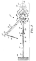
- the apparatus 10 is generally comprised of a pusher ball 12, an elastomeric annular collar 14, a positioner flange 16, a positioner arm 18, a retainer nut 20 and a pusher arm 22. All of the aforegoing are preferably comprised of type 304 stainless steel, except the collar 14 which is preferably comprised of a low durometer silicone rubber. A suitable silicone rubber is Dow Coming MDX-4-4 210 clean grade elastomer.
- the pusher ball 12 preferably includes a part spherical outer surface 24 adapted to generally mate with a part spherical recessed surface 26 within an acetabular cup 28.
- the cup 28 is shown in phantom line representation in Figures 2 and 3.
- the recessed surface 26 within the cup 28 is best seen in Figure 2.
- the recessed surface 26 is dimensioned to receive a conventional prosthetic femoral head, not shown.
- the pusher ball 12 further includes a planar surface 30, a threaded recess 31, and an undercut annular lip 32.
- the annular lip 32 is defined by two orthogonally arranged annular surfaces 33 and 35 which connect the outer surface 24 with the planar surface 30.
- the elastomeric annular collar 14 includes first and second major, opposite surfaces 34 and 36, an outer cylindrical surface 38 and an inner cylindrical surface 40.
- the surface 36 is shown in Figure 2.
- the inner cylindrical surface 40 is dimensioned to generally mate with the annular surface 33 of the pusher ball 12 to abut the first major surface 34 of the collar 14 with the surface 35 of the lip 32 when the elastomeric annular collar 14 is received within the annular lip 32. Further, when the collar 14 is so received, the surface 36 projects from the lip 32 in a manner and for a purpose to be explained below.
- the positioner flange 16 includes first and second major, opposite surfaces 42 and 44 and a connecting edge surface 46, as best shown in Figure 2, providing the flange 16 with a generally circular, disc-like or cylindrical shape.
- the circular, disc-like shape is broken up by a pair of preferably planar and parallel edge surface portions 48 and 50 and an inwardly extending edge surface portion 52.
- the inwardly extending edge surface portion 52 extends from a first location on the periphery of the circular, disc-like portion of the edge surface 46 generally to the center of the flange 16 in a plane parallel to the planar edge surface portions 48 and 50 and back to a second location on the periphery of the circular, disc-like portion of the edge surface 46 to define a radially extending slot 54 within the flange 16.
- the slot 54 is dimensioned to receive a portion of the pusher arm 22.
- the positioner arm 18 includes a first end portion 56 affixed to the flange 16, an intermediate straight portion 58 defining a predetermined angle lying between the positioner arm 18 and the pusher arm 22 when these two arms 18 and 22 are affixed in a manner to be explained, and a second end portion 60 opposite the first end portion 56.
- the second end portion 60 preferably includes an anteversion pin 62.
- the pin 62 is provided with an intermediate threaded portion 64 which complementarily mates with either of two threaded through portions 66 of the second end portion 60.
- One of the threaded portions 66 is identified with an « R » and is used in determining the proper anteversion angle during a right hip surgical procedure and the other is identified with an « L and is used in determining the proper anteversion angle during a left hip surgical procedure. The manner in which this is done will be explained below.
- the retainer nut 20 includes a cylindrical stand off portion 68 having a contact surface 70 and a knurled grip portion 72.
- the retainer nut 20 has a threaded through bore portion 73 which receives the pusher arm 22.
- the pusher arm 22 includes a first end threaded portion 74 which is dimensioned to complementarily mate with the threaded recess 31 within the pusher ball 12 so that the pusher arm 22 can be affixed to the pusher ball 12.
- the pusher arm 22 also includes an intermediate straight portion 76 and; second end portion 78 which is opposite the first end portion 74.
- the intermediate straight portion 76 preferably includes a flattened part 80 which is dimensioned to be received within the slot 54 within the flange 16 to face the first major surface 42 of the flange 16 with the pusher ball 12 along the intermediate portion 76 of the pusher arm 22.
- the intermediate straight portion 76 further includes a threaded part 52 which is dimensioned to complementarily mate with the threaded through bore portion 73 of the retainer nut 20 so that the retainer nut 20 can be movably mounted on the pusher arm 22 for a purpose to be described.
- the second end portion 78 is preferably provided with a conventional handle portion 84.
- the handle portion 84 preferably lies in the plane formed by pusher arm 22 and positioner arm 18.
- the anteversion pin is screwed into one of the two threaded through portions 66 of the positioner arm 18 to establish the proper anteversion angle for a right or left total hip replacement, as the case may be.
- the threaded through portions 66 are oriented within the positioner arm 18 to define an angle between the straight anteversion pin 62 and the straight intermediate portion 76 of the pusher arm 22 of between 65 and 75 degrees and preferably about 70 degrees, as measured from the plane formed by the pusher arm 22, the positioner arm 18, and the handle portion 84.
- the pin 62 lies in a plane that is parallel to a reference plane.
- the reference plane includes the pusher arm and is perpendicular to the earlier-described plane formed by the pusher arm 22, the positioner arm 18, and the handle portion 84.
- the pin 62 intersects the plane of the pusher arm 22, the positioner arm 18, and the handle portion 84 at the preferred angle of 70 degrees to provide a preferred anteversion angle of 20 degrees.
- the retainer nut 20 is screwed onto the threaded part 82 of the pusher arm 22. This can be accomplished by screwing the retainer nut 20 through the first end threaded portion 74 of the pusher arm 22 or by merely passing portion 74 through the nut 20, depending upon the dimensions of the portion 74.
- the portion 74 is next passed through the elastomeric annular collar 14 and screwed into the threaded recess 31 within the pusher ball 12.
- the positioner arm 18 is engaged with the pusher arm 22 by sliding the flattened part 80 of the pusher arm 22 within the slot 54 of the flange 16 and positioning the flangé 16 between the elastomeric annular collar 14 and the retainer nut 20 with the first major surface 42 of the flange 16 generally facing the pusher ball 12 and the second major surface 44 of the flange 16 generally facing the retainer nut 20.
- the elastomeric annular collar 14 is received within the undercut annular lip 32 of the pusher ball 12 to juxtapose the one major surface 34 of collar 14 with annular surface 35 of lip 32 and inner cylindrical surface 40 of collar 14 with annular surface 33 of lip 32.
- the inner cylindrical surface 40 extends beyond surface 33 to project the major surface 36 of the collar 14 beyond the lip 32 in a plane generally normal to a long axis 86 of the apparatus 10 ; i. e., in a plane generally parallel with the first major surface 42 of the flange 16 when the surface 42 is faced with the pusher ball 12 as earlier described.
- the retainer nut 20 is screwed towards the flange 16 until the flange 16 is pressed against the elastomeric annular collar 14, which is received within the lip 32.
- the part spherical outer surface 24 of the pusher ball 12 is received within the recessed surface 26 within the acetabular cup 28, and the nut 20 is adjusted until the elastomeric annular collar 14 is forced radially outward from the lip 32 to press the outer cylindrical surface 38 of the collar 14 against the recessed surface 26 and thereby affix the acetabular cup 28 with the pusher ball 12.
- a rim portion 88 of the cup 28 is preferably contacted with the first major surface 42 of the flange 16, as best shown in Figure 2, to facilitate cup positioning by providing a flat surface parallel to the face of the cup 28.
- the flange 16 is affixed relative to the pusher arm 22 to define an abduction angle lying between the intermediate straight portion 58 of the positioner arm 18 and the intermediate straight portion 76 of the pusher arm 22 in the range of 30 to 45 degrees.
- the angle of abduction is approximately 45 degrees.
- the acetabular cup 28 is oriented relative to the apparatus 10 in two planes, and if the cup 28 is symmetrical, as shown, this orients the cup 28 relative to the apparatus in all three planes. Generally, the axis of the cup 28 will coincide with the axis 86.
- the acetabular cup 28 can be inserted and aligned in a human acetabulum conventionally prepared with a suitable bone cement.
- the cup 28 must be anatomically aligned prior to its insertion in the acetabulum. This is accomplished by first aligning the long axis 86 of the pusher arm 22 with the long axis of the patient's torso. Next, the plane which is defined by the pusher arm 22, the T-handle 84 of the pusher arm 22, and the positioner arm 18 is rotated until it is aligned with the coronal plane of the patient. The cup 28 and the apparatus 10 are moved directly in front of the acetabulum during this portion of the alignment.
- the apparatus 10 is then rotated in the coronal plane of the patient until the positioner arm 18 is perpendicular to the long axis of the patient's torso.
- the direction of rotation is dependent upon the surgical exposure utilized and upon whether a left or right hip surgery is being performed. This direction is within the knowledge of one skilled in the art.
- This motion establishes the correct abduction angle.
- the apparatus 10 is rotated until the pin 62 is perpendicular to the coronal plane of the patient. This motion is equivalent to rotating the pusher arm 22 out of the coronal plane, in the sagittal plane, toward the head of the patient. This motion establishes the correct angle of anteversion.
- the cup 28 When the surgeon is satisfied that proper alignment has been achieved, the cup 28 is pushed firmly and directly into the acetabulum along the axis 86. Visualization of the cup 28 is aided by the planar edge surface portions 48 and 50 of the flange 16. The portions 48 and 50 expose the rim portion 88 of the cup 28 and afford the physician user a better view of the cup 28 in relation to the apparatus 10 and the acetabulum.
- the positioner arm 18 and flange 16 are removed in the following manner. While maintaining firm axial pressure on the pusher arm 22 via the handle 84, the retaining nut 20 is gently backed off by rotating it in a counterclockwise direction for several turns. After this is done, the flange 16 is pulled straight back for a short distance, and then separated from the pusher arm 22 and subsequently removed from the surgical field altogether, while axial pressure is still maintained through the pusher arm 22. Removal of the flange 16 releases the elastomeric annular collar 14, which can be pulled gently from the recess of the cup 28 with a forceps, if it does not pull out of the cup 28 with removal of the flange 16.
Landscapes
- Health & Medical Sciences (AREA)
- Transplantation (AREA)
- Orthopedic Medicine & Surgery (AREA)
- Heart & Thoracic Surgery (AREA)
- Cardiology (AREA)
- Oral & Maxillofacial Surgery (AREA)
- Engineering & Computer Science (AREA)
- Biomedical Technology (AREA)
- Physical Education & Sports Medicine (AREA)
- Vascular Medicine (AREA)
- Life Sciences & Earth Sciences (AREA)
- Animal Behavior & Ethology (AREA)
- General Health & Medical Sciences (AREA)
- Public Health (AREA)
- Veterinary Medicine (AREA)
- Prostheses (AREA)
Abstract
Claims (6)
Applications Claiming Priority (2)
| Application Number | Priority Date | Filing Date | Title |
|---|---|---|---|
| US714532 | 1985-03-21 | ||
| US06/714,532 US4632111A (en) | 1985-03-21 | 1985-03-21 | Acetabular cup positioning apparatus |
Publications (2)
| Publication Number | Publication Date |
|---|---|
| EP0216794A1 EP0216794A1 (fr) | 1987-04-08 |
| EP0216794B1 true EP0216794B1 (fr) | 1989-12-13 |
Family
ID=24870404
Family Applications (1)
| Application Number | Title | Priority Date | Filing Date |
|---|---|---|---|
| EP86900990A Expired EP0216794B1 (fr) | 1985-03-21 | 1986-01-27 | Dispositif de positionnement de calotte cotyloide |
Country Status (6)
| Country | Link |
|---|---|
| US (1) | US4632111A (fr) |
| EP (1) | EP0216794B1 (fr) |
| JP (1) | JPS62502241A (fr) |
| KR (1) | KR870700013A (fr) |
| DE (1) | DE3667397D1 (fr) |
| WO (1) | WO1986005384A1 (fr) |
Cited By (13)
| Publication number | Priority date | Publication date | Assignee | Title |
|---|---|---|---|---|
| DE29609632U1 (de) * | 1996-05-30 | 1996-11-07 | Fennen, Dietmar, 21640 Horneburg | Automatisches Pfannenpreßinstrument |
| DE19704577A1 (de) * | 1997-02-07 | 1998-08-13 | Aesculap Ag & Co Kg | Handhabungsinstrument von Gelenkkomponenten mit Gelenkflächen |
| DE19963456A1 (de) * | 1999-12-28 | 2001-11-08 | Markus Uttikal | Chirurgisches Instrument |
| US7237556B2 (en) | 2002-02-11 | 2007-07-03 | Smith & Nephew, Inc. | Image-guided fracture reduction |
| US7477926B2 (en) | 2004-03-31 | 2009-01-13 | Smith & Nephew, Inc. | Methods and apparatuses for providing a reference array input device |
| US7547307B2 (en) | 2001-02-27 | 2009-06-16 | Smith & Nephew, Inc. | Computer assisted knee arthroplasty instrumentation, systems, and processes |
| US7764985B2 (en) | 2003-10-20 | 2010-07-27 | Smith & Nephew, Inc. | Surgical navigation system component fault interfaces and related processes |
| US7794467B2 (en) | 2003-11-14 | 2010-09-14 | Smith & Nephew, Inc. | Adjustable surgical cutting systems |
| US7862570B2 (en) | 2003-10-03 | 2011-01-04 | Smith & Nephew, Inc. | Surgical positioners |
| DE202011050009U1 (de) | 2011-04-29 | 2011-07-14 | Aesculap Ag | Chirurgische Adaptervorrichtung für ein Gelenkimplantat und chirurgisches System |
| US8109942B2 (en) | 2004-04-21 | 2012-02-07 | Smith & Nephew, Inc. | Computer-aided methods, systems, and apparatuses for shoulder arthroplasty |
| US8177788B2 (en) | 2005-02-22 | 2012-05-15 | Smith & Nephew, Inc. | In-line milling system |
| DE102011050019A1 (de) | 2011-04-29 | 2012-10-31 | Aesculap Ag | Chirurgische Adaptervorrichtung für ein Gelenkimplantat und chirurgisches System |
Families Citing this family (178)
| Publication number | Priority date | Publication date | Assignee | Title |
|---|---|---|---|---|
| US4716894A (en) * | 1986-08-27 | 1988-01-05 | Zimmer, Inc. | Acetabular cup inserting instrument |
| DE58900119D1 (de) * | 1988-02-04 | 1991-06-27 | Protek Ag | Chirurgisches instrument zum einsetzen von hueftpfannen-prothesen. |
| US4995875A (en) * | 1988-05-27 | 1991-02-26 | Cecil Coes | Femoral elevating tool |
| GB8819589D0 (en) * | 1988-08-17 | 1988-09-21 | Minnesota Mining & Mfg | Acetabular component of hip joint prosthesis |
| US5217499A (en) * | 1988-08-17 | 1993-06-08 | Minnesota Mining And Manufacturing Company | Rim-bearing acetabular component of hip joint prosthesis |
| GB8819588D0 (en) * | 1988-08-17 | 1988-09-21 | Minnesota Mining & Mfg | Screw-threaded acetabular component of hip joint prosthesis |
| US5019083A (en) * | 1989-01-31 | 1991-05-28 | Advanced Osseous Technologies, Inc. | Implanting and removal of orthopedic prostheses |
| US5045054A (en) * | 1990-02-06 | 1991-09-03 | Advanced Osseous Technologies Inc. | Apparatus for implantation and extraction of osteal prostheses |
| US5037424A (en) * | 1989-12-21 | 1991-08-06 | Aboczsky Robert I | Instrument for orienting, inserting and impacting an acetabular cup prosthesis |
| US4987904A (en) * | 1990-03-22 | 1991-01-29 | Wilson James T | Method and apparatus for bone size gauging |
| USD331461S (en) | 1990-11-21 | 1992-12-01 | Zimmer, Inc. | Acetabular cup prosthesis positioning tool |
| US5098437A (en) * | 1991-02-13 | 1992-03-24 | Pfizer Hospital Products Group, Inc. | Acetabular cup positioning insert |
| US5171243A (en) * | 1991-02-13 | 1992-12-15 | Pfizer Hospital Products Group, Inc. | Acetabular cup positioning insert |
| US5061270A (en) * | 1991-03-18 | 1991-10-29 | Aboczky Robert I | System for orienting, inserting and impacting an acetabular cup prosthesis |
| GB9121132D0 (en) * | 1991-10-04 | 1991-11-13 | Johnson & Johnson Orthopaedics | An acetabular cup inserter |
| US5284483A (en) * | 1992-09-16 | 1994-02-08 | Zimmer, Inc. | Acetabular cup inserting instrument |
| GB9221257D0 (en) * | 1992-10-09 | 1992-11-25 | Minnesota Mining & Mfg | Glenoid alignment guide |
| US5250051A (en) * | 1993-02-08 | 1993-10-05 | Zimmer, Inc. | Acetabular cup positioner with slaphammer mechanism for the removal of the sighting guide |
| US5584837A (en) * | 1993-08-13 | 1996-12-17 | Petersen; Thomas D. | Acetabular cup inserter for orthopedic |
| US5364403A (en) * | 1993-09-20 | 1994-11-15 | Zimmer, Inc. | Acetabular cup positioner |
| US5954727A (en) * | 1993-10-29 | 1999-09-21 | Howmedica Inc. | Acetabular cup positioning tool and method of positioning an acetabular cup |
| US5431657A (en) * | 1994-05-23 | 1995-07-11 | Zimmer, Inc. | Instrument for installing an acetabular cup assembly |
| GB9416215D0 (en) * | 1994-08-11 | 1994-10-05 | Howmedica | Acetabular bone graft impactor |
| US5474560A (en) * | 1994-09-26 | 1995-12-12 | Zimmer, Inc. | Prosthetic acetabular cup inserter |
| US5683399A (en) * | 1995-12-01 | 1997-11-04 | Stelkast Incorporated | Acetabular cup insertion tool |
| DE19611249A1 (de) * | 1996-03-22 | 1997-09-25 | Cerasiv Gmbh | Kombination aus einer Gelenkprothese und einem Ausziehwerkzeug |
| FR2755603B1 (fr) * | 1996-11-12 | 1999-02-26 | Jacques Preaut | Ensemble d'ancillaires pour la pose de cotyles de protheses de hanche, et ensemble prothetique de cotyle pret a etre pose |
| US5951564A (en) * | 1996-12-18 | 1999-09-14 | Bristol-Myers Squibb Company | Orthopaedic positioning apparatus |
| US5904688A (en) * | 1997-12-30 | 1999-05-18 | Bristol-Myers Squibb Co. | Orthopaedic assembly including an acetabular cup and cup inserter |
| FR2782262B1 (fr) | 1998-08-17 | 2001-02-09 | Michel Porte | Cotyle d'essai ou implantable a orientation reglable |
| US6152930A (en) * | 1998-10-28 | 2000-11-28 | Depuy Orthopaedics, Inc. | Acetabular cup extraction system |
| SE514561C2 (sv) * | 1999-07-27 | 2001-03-12 | Bo Tillander | Rikt- och kompressionsinstrument avsett att användas vid höftproteskirurgi |
| NO994445D0 (no) | 1999-09-13 | 1999-09-13 | Bjoern Franc Iversen | FremgangsmÕte samt verktöy for kontroll av innbyrdes vinkel mellom delene i hofteleddsprotese |
| US6830570B1 (en) * | 1999-10-21 | 2004-12-14 | Sdgi Holdings, Inc. | Devices and techniques for a posterior lateral disc space approach |
| US6917827B2 (en) * | 2000-11-17 | 2005-07-12 | Ge Medical Systems Global Technology Company, Llc | Enhanced graphic features for computer assisted surgery system |
| US7497874B1 (en) | 2001-02-23 | 2009-03-03 | Biomet Manufacturing Corp. | Knee joint prosthesis |
| US20020120340A1 (en) | 2001-02-23 | 2002-08-29 | Metzger Robert G. | Knee joint prosthesis |
| CN100525721C (zh) * | 2001-11-02 | 2009-08-12 | 国际专利所有者(开曼)有限公司 | 用于股骨上的外科手术夹具 |
| GB0210363D0 (en) * | 2002-05-07 | 2002-06-12 | Depuy Int Ltd | Assembly for use in orthopaedic surgery |
| US20030229352A1 (en) | 2002-06-10 | 2003-12-11 | Penenberg Brad L. | Apparatus for and method of providing a hip replacement |
| US6997928B1 (en) | 2002-06-10 | 2006-02-14 | Wright Medical Technology, Inc. | Apparatus for and method of providing a hip replacement |
| US6986792B2 (en) | 2002-09-13 | 2006-01-17 | Smith & Nephew, Inc. | Prostheses |
| FR2850010B1 (fr) * | 2003-01-17 | 2005-12-02 | Tornier Sa | Ancillaire de pose d'un cotyle prothetique pour une prothese de hanche |
| US7008430B2 (en) * | 2003-01-31 | 2006-03-07 | Howmedica Osteonics Corp. | Adjustable reamer with tip tracker linkage |
| GB0302409D0 (en) * | 2003-02-03 | 2003-03-05 | Depuy Int Ltd | A cup component of an orthopaedics joint prosthesis |
| US7247158B2 (en) * | 2003-02-04 | 2007-07-24 | Wright Medical Technology, Inc. | Acetabular impactor |
| US7037310B2 (en) * | 2003-10-21 | 2006-05-02 | Wright Medical Technology Inc | Acetabular impactor |
| US7105028B2 (en) * | 2003-10-21 | 2006-09-12 | Wright Medical Technology, Inc. | Tissue preserving and minimally invasive hip replacement surgical procedure |
| US7335207B1 (en) * | 2003-11-26 | 2008-02-26 | Biomet Manufacturing Corp. | Minimally invasive cup impactor |
| US7931656B2 (en) * | 2004-01-05 | 2011-04-26 | Paramount Medical Instruments, L.L.C. | Acetabular shell impactor |
| GB0405059D0 (en) * | 2004-03-05 | 2004-04-07 | Benoist Girard Sas | Prosthetic acetabular cup inserter |
| GB0420346D0 (en) * | 2004-09-13 | 2004-10-13 | Finsbury Dev Ltd | Tool |
| FR2876278B1 (fr) | 2004-10-13 | 2007-10-26 | Thomas Gradel | Instruments de pose de cotyle |
| US7682363B2 (en) * | 2004-12-09 | 2010-03-23 | Greatbatch Medical S.A. | Inserter for minimally invasive joint surgery |
| US8277457B1 (en) | 2004-12-09 | 2012-10-02 | Greatbatch Medical S.A. | Orthopaedic inserter using a collet mechanism |
| US7976548B2 (en) * | 2005-08-24 | 2011-07-12 | Greatbatch Medical S.A. | Surgical tool holder for facilitated sterilization |
| US7621921B2 (en) * | 2006-01-25 | 2009-11-24 | Symmetry Medical, Inc | Split thread orthopaedic implant impactor |
| US7513899B2 (en) * | 2006-01-27 | 2009-04-07 | Howmedica Osteonics Corp. | Acetabular reamer connection mechanism |
| US9173661B2 (en) | 2006-02-27 | 2015-11-03 | Biomet Manufacturing, Llc | Patient specific alignment guide with cutting surface and laser indicator |
| US9113971B2 (en) | 2006-02-27 | 2015-08-25 | Biomet Manufacturing, Llc | Femoral acetabular impingement guide |
| US8568487B2 (en) | 2006-02-27 | 2013-10-29 | Biomet Manufacturing, Llc | Patient-specific hip joint devices |
| US8591516B2 (en) | 2006-02-27 | 2013-11-26 | Biomet Manufacturing, Llc | Patient-specific orthopedic instruments |
| US10278711B2 (en) | 2006-02-27 | 2019-05-07 | Biomet Manufacturing, Llc | Patient-specific femoral guide |
| US8864769B2 (en) | 2006-02-27 | 2014-10-21 | Biomet Manufacturing, Llc | Alignment guides with patient-specific anchoring elements |
| US9289253B2 (en) | 2006-02-27 | 2016-03-22 | Biomet Manufacturing, Llc | Patient-specific shoulder guide |
| US8298237B2 (en) | 2006-06-09 | 2012-10-30 | Biomet Manufacturing Corp. | Patient-specific alignment guide for multiple incisions |
| US8407067B2 (en) | 2007-04-17 | 2013-03-26 | Biomet Manufacturing Corp. | Method and apparatus for manufacturing an implant |
| US8133234B2 (en) | 2006-02-27 | 2012-03-13 | Biomet Manufacturing Corp. | Patient specific acetabular guide and method |
| US8608749B2 (en) | 2006-02-27 | 2013-12-17 | Biomet Manufacturing, Llc | Patient-specific acetabular guides and associated instruments |
| US8070752B2 (en) | 2006-02-27 | 2011-12-06 | Biomet Manufacturing Corp. | Patient specific alignment guide and inter-operative adjustment |
| US8377066B2 (en) | 2006-02-27 | 2013-02-19 | Biomet Manufacturing Corp. | Patient-specific elbow guides and associated methods |
| US8241293B2 (en) | 2006-02-27 | 2012-08-14 | Biomet Manufacturing Corp. | Patient specific high tibia osteotomy |
| US9918740B2 (en) | 2006-02-27 | 2018-03-20 | Biomet Manufacturing, Llc | Backup surgical instrument system and method |
| US8092465B2 (en) | 2006-06-09 | 2012-01-10 | Biomet Manufacturing Corp. | Patient specific knee alignment guide and associated method |
| US8282646B2 (en) | 2006-02-27 | 2012-10-09 | Biomet Manufacturing Corp. | Patient specific knee alignment guide and associated method |
| US8603180B2 (en) | 2006-02-27 | 2013-12-10 | Biomet Manufacturing, Llc | Patient-specific acetabular alignment guides |
| US20150335438A1 (en) | 2006-02-27 | 2015-11-26 | Biomet Manufacturing, Llc. | Patient-specific augments |
| US9907659B2 (en) | 2007-04-17 | 2018-03-06 | Biomet Manufacturing, Llc | Method and apparatus for manufacturing an implant |
| US7967868B2 (en) | 2007-04-17 | 2011-06-28 | Biomet Manufacturing Corp. | Patient-modified implant and associated method |
| US8473305B2 (en) | 2007-04-17 | 2013-06-25 | Biomet Manufacturing Corp. | Method and apparatus for manufacturing an implant |
| US9345548B2 (en) | 2006-02-27 | 2016-05-24 | Biomet Manufacturing, Llc | Patient-specific pre-operative planning |
| US9339278B2 (en) | 2006-02-27 | 2016-05-17 | Biomet Manufacturing, Llc | Patient-specific acetabular guides and associated instruments |
| US8535387B2 (en) | 2006-02-27 | 2013-09-17 | Biomet Manufacturing, Llc | Patient-specific tools and implants |
| US8858561B2 (en) | 2006-06-09 | 2014-10-14 | Blomet Manufacturing, LLC | Patient-specific alignment guide |
| US8608748B2 (en) | 2006-02-27 | 2013-12-17 | Biomet Manufacturing, Llc | Patient specific guides |
| DE102007020484A1 (de) | 2006-05-01 | 2007-12-13 | Precimed S.A. | Einführinstrument für die minimal invasive Gelenkchirurgie mit austauschbarem Gewinde |
| GB0608756D0 (en) * | 2006-05-03 | 2006-06-14 | Benoist Girard Sas | Prosthetic acetabular cup with outwardly projecting flange |
| US9795399B2 (en) | 2006-06-09 | 2017-10-24 | Biomet Manufacturing, Llc | Patient-specific knee alignment guide and associated method |
| DE202006010069U1 (de) * | 2006-06-28 | 2007-11-08 | Waldemar Link Gmbh & Co. Kg | Einsetzinstrument für Gelenkpfannen von Prothesen |
| US8163028B2 (en) | 2007-01-10 | 2012-04-24 | Biomet Manufacturing Corp. | Knee joint prosthesis system and method for implantation |
| US8328873B2 (en) | 2007-01-10 | 2012-12-11 | Biomet Manufacturing Corp. | Knee joint prosthesis system and method for implantation |
| JP5448842B2 (ja) | 2007-01-10 | 2014-03-19 | バイオメト マニファクチャリング コーポレイション | 膝関節プロテーゼシステムおよび埋込み方法 |
| US8187280B2 (en) | 2007-10-10 | 2012-05-29 | Biomet Manufacturing Corp. | Knee joint prosthesis system and method for implantation |
| US8562616B2 (en) | 2007-10-10 | 2013-10-22 | Biomet Manufacturing, Llc | Knee joint prosthesis system and method for implantation |
| US20090287309A1 (en) | 2007-01-30 | 2009-11-19 | Tornier Sas | Intra-articular joint replacement |
| JP2010519972A (ja) * | 2007-02-28 | 2010-06-10 | スミス アンド ネフュー インコーポレーテッド | 寛骨臼ライナーインサーターガイド |
| CA2692889A1 (fr) | 2007-07-11 | 2009-01-15 | Robert J. Daley | Procedes et appareil permettant de determiner le positionnement de broches dans le cadre de la chirurgie de la hanche |
| US8265949B2 (en) | 2007-09-27 | 2012-09-11 | Depuy Products, Inc. | Customized patient surgical plan |
| US8357111B2 (en) * | 2007-09-30 | 2013-01-22 | Depuy Products, Inc. | Method and system for designing patient-specific orthopaedic surgical instruments |
| US8398645B2 (en) * | 2007-09-30 | 2013-03-19 | DePuy Synthes Products, LLC | Femoral tibial customized patient-specific orthopaedic surgical instrumentation |
| EP2185108B1 (fr) | 2007-10-10 | 2018-01-17 | Orthosoft Inc. | Remplacement de hanche lors d'une intervention chirurgicale assistée par ordinateur |
| US8992538B2 (en) | 2008-09-30 | 2015-03-31 | DePuy Synthes Products, Inc. | Customized patient-specific acetabular orthopaedic surgical instrument and method of use and fabrication |
| US20100185202A1 (en) * | 2009-01-16 | 2010-07-22 | Lester Mark B | Customized patient-specific patella resectioning guide |
| US8398650B1 (en) | 2009-01-27 | 2013-03-19 | Greatbatch Medical S.A. | Offset cup impactor with an expandable dome for double mobility implants |
| US8170641B2 (en) | 2009-02-20 | 2012-05-01 | Biomet Manufacturing Corp. | Method of imaging an extremity of a patient |
| DE102009028503B4 (de) | 2009-08-13 | 2013-11-14 | Biomet Manufacturing Corp. | Resektionsschablone zur Resektion von Knochen, Verfahren zur Herstellung einer solchen Resektionsschablone und Operationsset zur Durchführung von Kniegelenk-Operationen |
| USD643921S1 (en) * | 2009-09-29 | 2011-08-23 | Karl Storz Gmbh & Co. Kg | Medical instrument |
| US8632547B2 (en) | 2010-02-26 | 2014-01-21 | Biomet Sports Medicine, Llc | Patient-specific osteotomy devices and methods |
| US9066727B2 (en) | 2010-03-04 | 2015-06-30 | Materialise Nv | Patient-specific computed tomography guides |
| JP5885354B2 (ja) | 2010-06-08 | 2016-03-15 | スミス アンド ネフュー インコーポレーテッド | インプラントの構成要素および方法 |
| USD685474S1 (en) | 2010-07-06 | 2013-07-02 | Tornier, Inc. | Prosthesis anchor |
| US8808302B2 (en) | 2010-08-12 | 2014-08-19 | DePuy Synthes Products, LLC | Customized patient-specific acetabular orthopaedic surgical instrument and method of use and fabrication |
| EP2422754B1 (fr) | 2010-08-27 | 2014-11-05 | Greatbatch Medical SA | Impacteur décalé pour coupelle avec une plaque de saisie pour implants à mobilité double |
| US9271744B2 (en) | 2010-09-29 | 2016-03-01 | Biomet Manufacturing, Llc | Patient-specific guide for partial acetabular socket replacement |
| US9968376B2 (en) | 2010-11-29 | 2018-05-15 | Biomet Manufacturing, Llc | Patient-specific orthopedic instruments |
| US8585709B2 (en) | 2011-01-17 | 2013-11-19 | Greatbatch Medical S.A. | Straight cup impactor with lever arm |
| US9119731B2 (en) | 2011-01-17 | 2015-09-01 | Greatbach Medical S.A. | Straight cup impactor |
| US9241745B2 (en) | 2011-03-07 | 2016-01-26 | Biomet Manufacturing, Llc | Patient-specific femoral version guide |
| US8715289B2 (en) | 2011-04-15 | 2014-05-06 | Biomet Manufacturing, Llc | Patient-specific numerically controlled instrument |
| US9675400B2 (en) | 2011-04-19 | 2017-06-13 | Biomet Manufacturing, Llc | Patient-specific fracture fixation instrumentation and method |
| US8956364B2 (en) | 2011-04-29 | 2015-02-17 | Biomet Manufacturing, Llc | Patient-specific partial knee guides and other instruments |
| US8668700B2 (en) | 2011-04-29 | 2014-03-11 | Biomet Manufacturing, Llc | Patient-specific convertible guides |
| EP2704651A4 (fr) * | 2011-05-03 | 2014-10-08 | Smith & Nephew Inc | Guides adaptés à un patient pour des implants orthopédiques |
| US8532807B2 (en) | 2011-06-06 | 2013-09-10 | Biomet Manufacturing, Llc | Pre-operative planning and manufacturing method for orthopedic procedure |
| US9084618B2 (en) | 2011-06-13 | 2015-07-21 | Biomet Manufacturing, Llc | Drill guides for confirming alignment of patient-specific alignment guides |
| US20130001121A1 (en) | 2011-07-01 | 2013-01-03 | Biomet Manufacturing Corp. | Backup kit for a patient-specific arthroplasty kit assembly |
| US8764760B2 (en) | 2011-07-01 | 2014-07-01 | Biomet Manufacturing, Llc | Patient-specific bone-cutting guidance instruments and methods |
| FR2978912A1 (fr) | 2011-08-10 | 2013-02-15 | Tornier Inc | Ancillaire d'extraction d'une prothese |
| US8597365B2 (en) | 2011-08-04 | 2013-12-03 | Biomet Manufacturing, Llc | Patient-specific pelvic implants for acetabular reconstruction |
| EP2561835B1 (fr) | 2011-08-26 | 2016-03-16 | Greatbatch Medical SA | Impacteur droit de cupules articulaires |
| US9066734B2 (en) | 2011-08-31 | 2015-06-30 | Biomet Manufacturing, Llc | Patient-specific sacroiliac guides and associated methods |
| US9295497B2 (en) | 2011-08-31 | 2016-03-29 | Biomet Manufacturing, Llc | Patient-specific sacroiliac and pedicle guides |
| EP2572679B1 (fr) | 2011-09-23 | 2015-07-15 | Greatbatch Medical SA | Support d'implant céramique |
| US9386993B2 (en) | 2011-09-29 | 2016-07-12 | Biomet Manufacturing, Llc | Patient-specific femoroacetabular impingement instruments and methods |
| US9301812B2 (en) | 2011-10-27 | 2016-04-05 | Biomet Manufacturing, Llc | Methods for patient-specific shoulder arthroplasty |
| US9451973B2 (en) | 2011-10-27 | 2016-09-27 | Biomet Manufacturing, Llc | Patient specific glenoid guide |
| KR20130046337A (ko) | 2011-10-27 | 2013-05-07 | 삼성전자주식회사 | 멀티뷰 디바이스 및 그 제어방법과, 디스플레이장치 및 그 제어방법과, 디스플레이 시스템 |
| WO2013062848A1 (fr) | 2011-10-27 | 2013-05-02 | Biomet Manufacturing Corporation | Guides glénoïdes spécifiques d'un patient |
| US9554910B2 (en) | 2011-10-27 | 2017-01-31 | Biomet Manufacturing, Llc | Patient-specific glenoid guide and implants |
| JP6282596B2 (ja) | 2011-12-07 | 2018-02-21 | スミス アンド ネフュー インコーポレイテッド | 整形外科用インプラントオーグメント |
| WO2013086235A1 (fr) | 2011-12-07 | 2013-06-13 | Smith & Nephew, Inc. | Dispositifs d'agrandissement orthopédiques ayant des poches enfoncées |
| US9237950B2 (en) | 2012-02-02 | 2016-01-19 | Biomet Manufacturing, Llc | Implant with patient-specific porous structure |
| US9060788B2 (en) | 2012-12-11 | 2015-06-23 | Biomet Manufacturing, Llc | Patient-specific acetabular guide for anterior approach |
| US9204977B2 (en) | 2012-12-11 | 2015-12-08 | Biomet Manufacturing, Llc | Patient-specific acetabular guide for anterior approach |
| US9839438B2 (en) | 2013-03-11 | 2017-12-12 | Biomet Manufacturing, Llc | Patient-specific glenoid guide with a reusable guide holder |
| US9579107B2 (en) | 2013-03-12 | 2017-02-28 | Biomet Manufacturing, Llc | Multi-point fit for patient specific guide |
| US9498233B2 (en) | 2013-03-13 | 2016-11-22 | Biomet Manufacturing, Llc. | Universal acetabular guide and associated hardware |
| US9826981B2 (en) | 2013-03-13 | 2017-11-28 | Biomet Manufacturing, Llc | Tangential fit of patient-specific guides |
| US9517145B2 (en) | 2013-03-15 | 2016-12-13 | Biomet Manufacturing, Llc | Guide alignment system and method |
| US20150112349A1 (en) | 2013-10-21 | 2015-04-23 | Biomet Manufacturing, Llc | Ligament Guide Registration |
| US12023253B2 (en) | 2014-01-24 | 2024-07-02 | Howmedica Osteonics Corp. | Humeral implant anchor system |
| US10456264B2 (en) | 2014-01-24 | 2019-10-29 | Tornier, Inc. | Humeral implant anchor system |
| US10282488B2 (en) | 2014-04-25 | 2019-05-07 | Biomet Manufacturing, Llc | HTO guide with optional guided ACL/PCL tunnels |
| US10568649B2 (en) | 2014-05-06 | 2020-02-25 | Howmedica Osteonics Corp. | Acetabular reamer |
| US9408616B2 (en) | 2014-05-12 | 2016-08-09 | Biomet Manufacturing, Llc | Humeral cut guide |
| US9561040B2 (en) | 2014-06-03 | 2017-02-07 | Biomet Manufacturing, Llc | Patient-specific glenoid depth control |
| US9839436B2 (en) | 2014-06-03 | 2017-12-12 | Biomet Manufacturing, Llc | Patient-specific glenoid depth control |
| US9833245B2 (en) | 2014-09-29 | 2017-12-05 | Biomet Sports Medicine, Llc | Tibial tubercule osteotomy |
| US9826994B2 (en) | 2014-09-29 | 2017-11-28 | Biomet Manufacturing, Llc | Adjustable glenoid pin insertion guide |
| FR3028174B1 (fr) * | 2014-11-07 | 2022-07-01 | Dedienne Sante | Ensemble pour l'implantation d'un cotyle |
| US9820868B2 (en) | 2015-03-30 | 2017-11-21 | Biomet Manufacturing, Llc | Method and apparatus for a pin apparatus |
| US10226262B2 (en) | 2015-06-25 | 2019-03-12 | Biomet Manufacturing, Llc | Patient-specific humeral guide designs |
| US10568647B2 (en) | 2015-06-25 | 2020-02-25 | Biomet Manufacturing, Llc | Patient-specific humeral guide designs |
| US10034753B2 (en) | 2015-10-22 | 2018-07-31 | DePuy Synthes Products, Inc. | Customized patient-specific orthopaedic instruments for component placement in a total hip arthroplasty |
| US10463499B2 (en) | 2016-03-25 | 2019-11-05 | Tornier, Inc. | Stemless shoulder implant with fixation components |
| ES2700650T3 (es) | 2016-04-12 | 2019-02-18 | Dedienne Sante | Conjunto para la implantación de un acetábulo en una cavidad acetabular |
| US10245161B2 (en) | 2016-07-12 | 2019-04-02 | Dedienne Sante | Assembly for implanting an acetabular cup in a cotyloid cavity |
| US11129724B2 (en) | 2016-07-28 | 2021-09-28 | Howmedica Osteonics Corp. | Stemless prosthesis anchor component |
| US10722310B2 (en) | 2017-03-13 | 2020-07-28 | Zimmer Biomet CMF and Thoracic, LLC | Virtual surgery planning system and method |
| WO2019060780A2 (fr) | 2017-09-25 | 2019-03-28 | Tornier, Inc. | Composants d'ancrage de prothèse sans tige spécifique au patient |
| US11399948B2 (en) | 2017-12-11 | 2022-08-02 | Howmedica Osteonics Corp. | Stemless prosthesis anchor components and kits |
| US11051829B2 (en) | 2018-06-26 | 2021-07-06 | DePuy Synthes Products, Inc. | Customized patient-specific orthopaedic surgical instrument |
| WO2020072452A1 (fr) | 2018-10-02 | 2020-04-09 | Tornier, Inc. | Composants et ensembles de prothèse d'épaule |
| US11484416B2 (en) * | 2019-06-04 | 2022-11-01 | DePuy Synthes Products, Inc. | Implant insertion tool for implanting an acetabular component and associated surgical method |
| US12370051B2 (en) | 2019-10-01 | 2025-07-29 | Howmedica Osteonics Corp. | Shoulder prosthesis components and assemblies |
| USD951449S1 (en) | 2019-10-01 | 2022-05-10 | Howmedica Osteonics Corp. | Humeral implant |
| US11090163B1 (en) * | 2021-01-09 | 2021-08-17 | Zafer Termanini | Interlocking reverse hip prosthesis with removable tapered central post |
| US12419689B2 (en) | 2021-06-29 | 2025-09-23 | DePuy Synthes Products, Inc. | Patient-specific registration jig and associated method for registering an orthopaedic surgical instrument to a patient |
Family Cites Families (5)
| Publication number | Priority date | Publication date | Assignee | Title |
|---|---|---|---|---|
| BE678171A (fr) * | 1965-04-06 | 1966-09-01 | ||
| US3859992A (en) * | 1973-06-06 | 1975-01-14 | Harlan C Amstutz | Vacuum-operated acetabular cup holder and positioner |
| US4305394A (en) * | 1980-12-22 | 1981-12-15 | Bertuch Jr Charles J | Acetabular cup positioning instrument |
| US4475549A (en) * | 1982-01-18 | 1984-10-09 | Indong Oh | Acetabular cup positioner and method |
| US4528980A (en) * | 1983-10-19 | 1985-07-16 | Howmedica, Inc. | Acetabulum sizer and drill guide |
-
1985
- 1985-03-21 US US06/714,532 patent/US4632111A/en not_active Expired - Lifetime
-
1986
- 1986-01-27 DE DE8686900990T patent/DE3667397D1/de not_active Expired - Lifetime
- 1986-01-27 KR KR860700826A patent/KR870700013A/ko not_active Withdrawn
- 1986-01-27 EP EP86900990A patent/EP0216794B1/fr not_active Expired
- 1986-01-27 WO PCT/US1986/000152 patent/WO1986005384A1/fr not_active Ceased
- 1986-01-27 JP JP61500874A patent/JPS62502241A/ja active Pending
Cited By (15)
| Publication number | Priority date | Publication date | Assignee | Title |
|---|---|---|---|---|
| DE29609632U1 (de) * | 1996-05-30 | 1996-11-07 | Fennen, Dietmar, 21640 Horneburg | Automatisches Pfannenpreßinstrument |
| DE19704577A1 (de) * | 1997-02-07 | 1998-08-13 | Aesculap Ag & Co Kg | Handhabungsinstrument von Gelenkkomponenten mit Gelenkflächen |
| DE19704577B4 (de) * | 1997-02-07 | 2006-06-29 | Aesculap Ag & Co. Kg | Handhabungsinstrument von Gelenkkomponenten mit Gelenkflächen |
| DE19963456A1 (de) * | 1999-12-28 | 2001-11-08 | Markus Uttikal | Chirurgisches Instrument |
| US7547307B2 (en) | 2001-02-27 | 2009-06-16 | Smith & Nephew, Inc. | Computer assisted knee arthroplasty instrumentation, systems, and processes |
| US7237556B2 (en) | 2002-02-11 | 2007-07-03 | Smith & Nephew, Inc. | Image-guided fracture reduction |
| US7862570B2 (en) | 2003-10-03 | 2011-01-04 | Smith & Nephew, Inc. | Surgical positioners |
| US8491597B2 (en) | 2003-10-03 | 2013-07-23 | Smith & Nephew, Inc. (partial interest) | Surgical positioners |
| US7764985B2 (en) | 2003-10-20 | 2010-07-27 | Smith & Nephew, Inc. | Surgical navigation system component fault interfaces and related processes |
| US7794467B2 (en) | 2003-11-14 | 2010-09-14 | Smith & Nephew, Inc. | Adjustable surgical cutting systems |
| US7477926B2 (en) | 2004-03-31 | 2009-01-13 | Smith & Nephew, Inc. | Methods and apparatuses for providing a reference array input device |
| US8109942B2 (en) | 2004-04-21 | 2012-02-07 | Smith & Nephew, Inc. | Computer-aided methods, systems, and apparatuses for shoulder arthroplasty |
| US8177788B2 (en) | 2005-02-22 | 2012-05-15 | Smith & Nephew, Inc. | In-line milling system |
| DE202011050009U1 (de) | 2011-04-29 | 2011-07-14 | Aesculap Ag | Chirurgische Adaptervorrichtung für ein Gelenkimplantat und chirurgisches System |
| DE102011050019A1 (de) | 2011-04-29 | 2012-10-31 | Aesculap Ag | Chirurgische Adaptervorrichtung für ein Gelenkimplantat und chirurgisches System |
Also Published As
| Publication number | Publication date |
|---|---|
| WO1986005384A1 (fr) | 1986-09-25 |
| EP0216794A1 (fr) | 1987-04-08 |
| JPS62502241A (ja) | 1987-09-03 |
| DE3667397D1 (de) | 1990-01-18 |
| KR870700013A (ko) | 1987-02-28 |
| US4632111A (en) | 1986-12-30 |
Similar Documents
| Publication | Publication Date | Title |
|---|---|---|
| EP0216794B1 (fr) | Dispositif de positionnement de calotte cotyloide | |
| US11298233B2 (en) | Method of implanting joint prosthesis with infinitely positionable head | |
| JP2532806B2 (ja) | 寛骨臼カップアッセンブリ | |
| EP0807426B1 (fr) | Prothèse d'essai acétabulaire | |
| US6273891B1 (en) | Method and apparatus for aligning a prosthetic element | |
| US6364910B1 (en) | Method and apparatus for use of a glenoid component | |
| EP0137040B1 (fr) | Coussinet a rotule pour articulation artificielle | |
| US8535323B2 (en) | Constraining ring inserter | |
| US20050137603A1 (en) | Acetabular cup positioning instrument | |
| JP2017035509A (ja) | 合成角インプラント | |
| US20110276100A1 (en) | Alignment guide | |
| US6623488B1 (en) | Pelvic alignment assembly | |
| CN114746049A (zh) | 用于植入物插入工具的可拆卸倾斜引导件和相关外科手术方法 | |
| JPH06296632A (ja) | ブローチハンドル装置 | |
| CA1267341A (fr) | Dispositif de positionnement de la cupule cotyloide | |
| CN115666451A (zh) | 偏置连接件、试验植入系统和允许可选择偏心率的植入系统 | |
| JPH11155890A (ja) | バイポーラ−ユニポーラ型代用大腿骨頭アダプタ | |
| IE920458A1 (en) | Acetabular cup positioning insert |
Legal Events
| Date | Code | Title | Description |
|---|---|---|---|
| PUAI | Public reference made under article 153(3) epc to a published international application that has entered the european phase |
Free format text: ORIGINAL CODE: 0009012 |
|
| AK | Designated contracting states |
Kind code of ref document: A1 Designated state(s): AT BE CH DE FR GB IT LI LU NL SE |
|
| 17P | Request for examination filed |
Effective date: 19870224 |
|
| RBV | Designated contracting states (corrected) |
Designated state(s): DE FR GB IT SE |
|
| 17Q | First examination report despatched |
Effective date: 19890313 |
|
| GRAA | (expected) grant |
Free format text: ORIGINAL CODE: 0009210 |
|
| AK | Designated contracting states |
Kind code of ref document: B1 Designated state(s): DE FR GB IT SE |
|
| ITF | It: translation for a ep patent filed | ||
| REF | Corresponds to: |
Ref document number: 3667397 Country of ref document: DE Date of ref document: 19900118 |
|
| ET | Fr: translation filed | ||
| PLBE | No opposition filed within time limit |
Free format text: ORIGINAL CODE: 0009261 |
|
| STAA | Information on the status of an ep patent application or granted ep patent |
Free format text: STATUS: NO OPPOSITION FILED WITHIN TIME LIMIT |
|
| 26N | No opposition filed | ||
| PGFP | Annual fee paid to national office [announced via postgrant information from national office to epo] |
Ref country code: FR Payment date: 19921210 Year of fee payment: 8 |
|
| PGFP | Annual fee paid to national office [announced via postgrant information from national office to epo] |
Ref country code: SE Payment date: 19921211 Year of fee payment: 8 Ref country code: DE Payment date: 19921211 Year of fee payment: 8 |
|
| ITTA | It: last paid annual fee | ||
| PG25 | Lapsed in a contracting state [announced via postgrant information from national office to epo] |
Ref country code: SE Effective date: 19940128 |
|
| PG25 | Lapsed in a contracting state [announced via postgrant information from national office to epo] |
Ref country code: FR Effective date: 19940930 |
|
| PG25 | Lapsed in a contracting state [announced via postgrant information from national office to epo] |
Ref country code: DE Effective date: 19941001 |
|
| REG | Reference to a national code |
Ref country code: FR Ref legal event code: ST |
|
| EUG | Se: european patent has lapsed |
Ref document number: 86900990.2 Effective date: 19940810 |
|
| PGFP | Annual fee paid to national office [announced via postgrant information from national office to epo] |
Ref country code: GB Payment date: 20010124 Year of fee payment: 16 |
|
| REG | Reference to a national code |
Ref country code: GB Ref legal event code: IF02 |
|
| PG25 | Lapsed in a contracting state [announced via postgrant information from national office to epo] |
Ref country code: GB Free format text: LAPSE BECAUSE OF NON-PAYMENT OF DUE FEES Effective date: 20020127 |
|
| GBPC | Gb: european patent ceased through non-payment of renewal fee |
Effective date: 20020127 |
|
| PG25 | Lapsed in a contracting state [announced via postgrant information from national office to epo] |
Ref country code: IT Free format text: LAPSE BECAUSE OF NON-PAYMENT OF DUE FEES;WARNING: LAPSES OF ITALIAN PATENTS WITH EFFECTIVE DATE BEFORE 2007 MAY HAVE OCCURRED AT ANY TIME BEFORE 2007. THE CORRECT EFFECTIVE DATE MAY BE DIFFERENT FROM THE ONE RECORDED. Effective date: 20050127 |