EP0216968B1 - Appareil de liaison par soudage sous pression - Google Patents
Appareil de liaison par soudage sous pression Download PDFInfo
- Publication number
- EP0216968B1 EP0216968B1 EP85306557A EP85306557A EP0216968B1 EP 0216968 B1 EP0216968 B1 EP 0216968B1 EP 85306557 A EP85306557 A EP 85306557A EP 85306557 A EP85306557 A EP 85306557A EP 0216968 B1 EP0216968 B1 EP 0216968B1
- Authority
- EP
- European Patent Office
- Prior art keywords
- chamber
- bonded
- bonding
- holder
- preparatory
- Prior art date
- Legal status (The legal status is an assumption and is not a legal conclusion. Google has not performed a legal analysis and makes no representation as to the accuracy of the status listed.)
- Expired
Links
- 238000003466 welding Methods 0.000 title claims description 9
- 238000005530 etching Methods 0.000 description 11
- 239000002184 metal Substances 0.000 description 11
- 229910052751 metal Inorganic materials 0.000 description 11
- 150000002739 metals Chemical class 0.000 description 8
- 238000000034 method Methods 0.000 description 8
- XKRFYHLGVUSROY-UHFFFAOYSA-N Argon Chemical compound [Ar] XKRFYHLGVUSROY-UHFFFAOYSA-N 0.000 description 6
- 239000011248 coating agent Substances 0.000 description 5
- 238000000576 coating method Methods 0.000 description 5
- 239000011261 inert gas Substances 0.000 description 5
- 239000000126 substance Substances 0.000 description 5
- 239000000919 ceramic Substances 0.000 description 4
- 229910052786 argon Inorganic materials 0.000 description 3
- 230000007547 defect Effects 0.000 description 3
- 239000007789 gas Substances 0.000 description 3
- 239000000463 material Substances 0.000 description 3
- 239000010409 thin film Substances 0.000 description 3
- 238000009792 diffusion process Methods 0.000 description 2
- 239000010408 film Substances 0.000 description 2
- 238000010438 heat treatment Methods 0.000 description 2
- 230000001680 brushing effect Effects 0.000 description 1
- 230000001419 dependent effect Effects 0.000 description 1
- 238000010586 diagram Methods 0.000 description 1
- 230000005484 gravity Effects 0.000 description 1
- 238000009434 installation Methods 0.000 description 1
- 238000011835 investigation Methods 0.000 description 1
- 150000002500 ions Chemical class 0.000 description 1
- 238000012544 monitoring process Methods 0.000 description 1
- 238000001953 recrystallisation Methods 0.000 description 1
- 238000000992 sputter etching Methods 0.000 description 1
- 238000005211 surface analysis Methods 0.000 description 1
Images

Classifications
-
- B—PERFORMING OPERATIONS; TRANSPORTING
- B23—MACHINE TOOLS; METAL-WORKING NOT OTHERWISE PROVIDED FOR
- B23K—SOLDERING OR UNSOLDERING; WELDING; CLADDING OR PLATING BY SOLDERING OR WELDING; CUTTING BY APPLYING HEAT LOCALLY, e.g. FLAME CUTTING; WORKING BY LASER BEAM
- B23K20/00—Non-electric welding by applying impact or other pressure, with or without the application of heat, e.g. cladding or plating
- B23K20/24—Preliminary treatment
-
- B—PERFORMING OPERATIONS; TRANSPORTING
- B23—MACHINE TOOLS; METAL-WORKING NOT OTHERWISE PROVIDED FOR
- B23K—SOLDERING OR UNSOLDERING; WELDING; CLADDING OR PLATING BY SOLDERING OR WELDING; CUTTING BY APPLYING HEAT LOCALLY, e.g. FLAME CUTTING; WORKING BY LASER BEAM
- B23K20/00—Non-electric welding by applying impact or other pressure, with or without the application of heat, e.g. cladding or plating
- B23K20/14—Preventing or minimising gas access, or using protective gases or vacuum during welding
Definitions
- the present invention relates to the bonding of metals or ceramics among themselves or ceramics to metals and the like, and in particular to a bonding apparatus suitable for the bonding of parts of precision machines.
- the pressure welding is remarkably dependent upon the surface state of metals, so that is is almost impossible in the even that the surface coat layer exists. Accordingly, the pressure welding is possible if a clean surface, on which the surface coat layer does not exist, can be obtained. It is, however, remarkably difficult to remove a surface coat without giving any strain to the surface, and it is difficult to remove the surface coat layer to make very remarkably small surface strain.
- metals can be readily bonded among themselves without showing any metallographical change or thermal strain of the material pressure welded, or any dimensional change of the portion pressure welded, and without requiring any special means such as heating treatment, by pressure welding them under superhigh vacuum of 10-9 mmHg (1,3 10-7 Pa) or more, after removing a metal surface coat by spattering with inert gas ions (Japanese Patent Application No. 53-32416).
- a bonding apparatus comprises holding means for a workpiece to be bonded, a pressing means for pressure welding workpieces to be bonded to each other, a superhigh vacuum bonding chamber capable of maintaining a vacuum of 10-9 mmHg (1,3.10-7 p a) or more provided with said holding means and said pressing means, characterised by a superhigh vacuum bonding preparatory chamber capable of maintaining a vacuum of 10-8 mmHg (1,3.10-SPa) or more connected with said superhigh vacuum bonding chamber through a gate valve and a conveying means for a workpiece to be bonded for conveying the workpieces to be bonded between said superhigh vacuum bonding preparatory chamber and said superhigh vacuum bonding chamber.
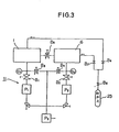
- the first portion is a superhigh vacuum bonding chamber (hereinafter referred to simply as a bonding chamber) 1.
- the bonding chamber 1 is held under superhigh vacuum of 10-9 mmHg (1,3.10- 7 Pa) or more and provided with a holding means 3 for fixedly holding two workpieces 2 to be bonded, a pressing means 4 for generating a minute pressure, a differential pressure type spatter-etching means 5 capable of spatter-etching surfaces to be bonded with inert gas with holding the vacuum of 10-9 mmHg (1,3.10- 7 Pa) in order to make the surfaces to be bonded clean surfaces, and substantially ideal ones, prior to the bonding operation.
- the second portion is a superhigh vacuum preparatory chamber (hereinafter referred to simply as a preparatory chamber) 6.
- the preparatory chamber 6 is held under high vacuum of 10- 8 mmHg (1,3.10-sPa) or more and cut off from the bonding chamber 1 by a gate valve 7.
- the preparatory chamber 6 communicates with an atmosphere when the workpiece 2 to be bonded is put in or removed but can be held under superhigh vacuum after the workpiece 2 to be bonded has been mounted on a plurality of holders 8.
- the preparatory chamber 6 is provided with a spatter-vapour coating apparatus 9 capable of coating a thin film of other substances on the surface of the workpiece 2 to be bonded.
- the third portion is a conveying means 10 for conveying the workpiece 2 to be bonded from the preparatory chamber 6 and mounting it on the holding means 3 of the bonding chamber 1.
- the fourth portion is a superhigh vacuum evacuating apparatus 11 for producing a superhigh vacuum atmosphere within the preparatory chamber 6 and the bonding chamber 1, as shown in Figure 3.
- the bonding chamber 1 is generally cylindrical in shape and is provided with a rotary table 12 therein which is controlled so as to be rotatable through suitable angles by a rotary apparatus 17 arranged outside the bonding chamber 1, if need arises.
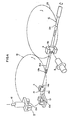
- This rotary table 12 is provided with a support 13 for a workpiece to be bonded, the support having an upwardly facing channel-shaped section fixedly mounted thereon as shown in Figure 4.
- the holding means 3 of the workpiece 2 to be bonded is constructed to hold the workpiece 2 within the bonding chamber 1 by engaging a collar member 14a of a workpiece holder 14 with a groove 13a in support 13.
- the bonding chamber 1 is provided in the upper portion thereof with a second support 15 for a workpiece to be bonded, the support comprising a part of the holding means 3 facing the support 13.
- the support 15 has an inverted channel shape section, which is opposed to that of the lower support 13, and is provided with a groove 15a so as to hold a holder 14 of a workpiece to be bonded in the reverse direction.
- This support 15 is connected with the pressing means 4, and is movable up and down, and is provided with a closing apparatus 16 for opening and closing the arms of the channel section support 15.
- the bonding chamber 1 is provided with the differential pressure type etching means 5 for etching the surface of the workpiece 2 to be bonded, if need arises.
- said differential pressure type etching means 5 an upper spatter-etching apparatus 5a is provided in the upper portion of the bonding chamber 1 at a side opposite to said support 15 while a lower spatter-etching apparatus 5b is provided in the lower portion of the bonding chamber 1 facing the second support 15.
- the bonding chamber 1 is provided with an exhaust port 18 connected with said superhigh vacuum evacuating apparatus 11, operation-monitoring ports 19, 20, an instrument port 21, a surface analysis port 22 and the like.
- the cylindrical preparatory chamber 6 is provided with a rotary table 23, which is similar to the rotary table 12 provided in the bonding chamber 1, four holders 8 being fixedly mounted on the rotary table 23 at regular intervals of 90 ° .
- These holders 8 have a channel-shaped section, which is generally the same as that of the support 13, as shown in Figure 4.
- the holders 8 are fixedly mounted so that the open side of the channel-shape is directed sidewards, and the workpiece 2 to be bonded is held by engaging the collar member 14a of the holder 14 with a groove 8a of the holder 8.
- the preparatory chamber 6 is provided with the spatter-vapour coating apparatus 9 on the side thereof facing to the holder 8, as the table 23 is turned, whereby a thin film of other substances can be coated on the surface of the workpiece 2 to be bonded which is mounted on the holder 8.
- the conveying means 10 is provided with a movable shaft 10a which is rotatable and movable in an axial direction, said movable shaft 10a passing through the side wall of the preparatory chamber 6 and extendable as far as the support 13 in the bonding chamber 1 through said holder 8 and said gate valve 7.
- This movable shaft 10a is provided with a screw member 10b at the forward end thereof, the workpiece 2 to be bonded being conveyed between the preparatory chamber 6 and the bonding chamber 1 by screwing this screw member 10b in a complimentary screw member 14b of the holder 14.
- an exhaust port 24 is connected with the superhigh vacuum evacuating apparatus 11.
- the superhigh vacuum evacuating apparatus 11 comprises superhigh vacuum pumps Pi, P 2 capable of obtaining a vacuum of about 10-2 to 10-10 mmHg, (1,3 to 1,3.10-spa), a high vacuum pump P capable of obtaining a vacuum of about 10-4 mmHg (1,3.10- 2 Pa), vacuum gauges Gi, G 2 , valves Bi, B 2 , Bs, B 4 , Bs, Bs, 8 7 , Be arranged between the pumps Pi, P 2 , Ps, the bonding chamber 1, the preparatory chamber 6 and an argon gas bomb 25, the inside of the bonding chamber 1 and the preparatory chamber 6 being adjusted to the desired vacuum and simultaneously the bonding chamber 1 and the preparatory chamber 6 being fed with argon gas used for ion-etching or ion-spatter vapour coating by appropriate opening and closing the various valves.
- the surface of the workpiece 2 to be bonded put in the superhigh vacuum preparatory chamber 6 can be subjected to the spatter-vapour coating if need arises.
- an inert gas such as argon gas is introduced into the preparatory chamber 6 under the vacuum of about 10-5 mmHg (1,3.10-3Pa) and a substance for the desired thin film can be coated on the surface to be spatter-bonded as a spatter-vapour coated film by use of this inert gas.
- a high vacuum of 10- s mmHg (1,3.10-6Pa) is again produced within the preparatory chamber 6.
- the screw member 10b is screwed in the screw member 14b of a holder 14 by rotating the movable shaft 10a and the holder 14 is removed from the holder 8 by axially moving the movable shaft 10a.
- the holder 14 is fixedly engaged with the support 13 in the bonding chamber 1 by rotating the rotary table 23 in the preparatory chamber 6 by 45 ° , rotating the movable shaft 10a by 90 ° , and simultaneously opening the gate valve 7 to pass the holder 14 through the gate valve 7 and engage the holder 14 in the support 13.
- the movable shaft 10a is rotated in the reverse direction to remove from the holder 14 and return to the original position in the preparatory chamber 6.
- the rotary table 23 is further rotated by 45 ° to screw the pointed end of the movable shaft 10a in another holder 14, the movable shaft 10a being axially moved to remove the holder 14 from the holder 8, and the movable shaft 10a being rotated by 90 ° .
- the rotary table 12 is under the condition that it is rotated by 180° and the support 15 is under the condition that it is lowered in to a fixed position aligned in the path of the shaft 10a.
- the movable shaft 10a is axially moved to fixedly engage the holder 14 with the support 15, the movable shaft 10a being rotated to remove from the holder 14, the movable shaft 10a being returned to the original position in the preparatory chamber 6, and simultaneously the gate valve 7 being closed.
- one of the workpieces 2 to be bonded fixedly held in the bonding chamber 1 is mounted on the pointed end portion of the pressing means 4 and the other one is mounted on the rotary table 12.
- the surfaces of the workpieces 2 to be bonded are fixed at the positions facing to the upper and lower differential pressure type spatter-etching apparatus 5a, 5b respectively, so that the surfaces of the workpieces 2 to be bonded are subjected to the spatter-etching until the clean surface, which is substantially an ideal one, is obtained.
- a spatter-etching apparatus 5a, 5b on the market can carry out the spatter-etching by use of an inert gas under a superhigh vacuum of 10- 9 mmHg (1,3.10- 7p a) and can spatter-etch an area of a certain extent or more by the surface-scanning.
- the workpieces 2 to be bonded to which the substantially ideal clean surfaces were given, are positioned face to face with each other by rotating the rotary table 12 by 180 ° . Under this condition, minute pressure is added to both surfaces to be bonded by means of the pressing means 4 to carry out the bonding operation.
- the gate valve 7 between the bonding chamber 1 and the preparatory chamber 6 is opened and the movable shaft 10a inserted and screwed in the holder 14 whilst removing the pressure from the pressing means 4.
- both arms of the support 15 are opened by means of the closing apparatus 16 to loosen the engagement of the holder 14 with the support 15, the movable shaft 10a being returned into the preparatory chamber 6, the holder 14 being engaged with the holder 8 in the preparatory chamber 6, and simultaneously the gate valve 7 being closed.
- both of two bonded workpieces are brought into the preparatory chamber 6 in bonded condition and then can be taken out of it by returning the pressure inside the preparatory chamber 6 to an atmospheric pressure.
- the procedure from the installation of the workpiece to be bonded in the bonding chamber to its removal from the bonding chamber is over.
- a large number of bonded products can be obtained by repeating the above described procedure.
- the preparatory chamber 6 disclosed is provided with four holders 8 therein, so that two bonding operations can be carried out without returning the pressure inside the preparatory chamber 6 to an atmospheric pressure, it goes without saying that a larger number of bonding operations can be continuously carried out by increasing the number of the holder 8 in the preparatory chamber 6.
- a bonding chamber can be always held under superhigh vacuum and the inside of the bonding chamber can be always kept clean, so that not only the inside of the bonding chamber can be free from stains in the open air but also the time required for producing a superhigh vacuum atmosphere can be shortened thereby effectively carrying out a superhigh vacuum bonding process.
Landscapes
- Engineering & Computer Science (AREA)
- Mechanical Engineering (AREA)
- Pressure Welding/Diffusion-Bonding (AREA)
- Ceramic Products (AREA)
Claims (5)
Priority Applications (1)
| Application Number | Priority Date | Filing Date | Title |
|---|---|---|---|
| DE8585306557T DE3576069D1 (de) | 1985-09-16 | 1985-09-16 | Pressschweissverbindungsgeraet. |
Applications Claiming Priority (1)
| Application Number | Priority Date | Filing Date | Title |
|---|---|---|---|
| JP59041221A JPS60187485A (ja) | 1984-03-06 | 1984-03-06 | 接合装置 |
Publications (2)
| Publication Number | Publication Date |
|---|---|
| EP0216968A1 EP0216968A1 (fr) | 1987-04-08 |
| EP0216968B1 true EP0216968B1 (fr) | 1990-02-21 |
Family
ID=12602337
Family Applications (1)
| Application Number | Title | Priority Date | Filing Date |
|---|---|---|---|
| EP85306557A Expired EP0216968B1 (fr) | 1984-03-06 | 1985-09-16 | Appareil de liaison par soudage sous pression |
Country Status (3)
| Country | Link |
|---|---|
| US (1) | US4709844A (fr) |
| EP (1) | EP0216968B1 (fr) |
| JP (1) | JPS60187485A (fr) |
Cited By (1)
| Publication number | Priority date | Publication date | Assignee | Title |
|---|---|---|---|---|
| RU2184020C1 (ru) * | 2001-07-24 | 2002-06-27 | Государственное унитарное предприятие "Научно-исследовательский и конструкторский институт энерготехники" | Установка для диффузионной сварки внахлестку трубчатых переходников |
Families Citing this family (11)
| Publication number | Priority date | Publication date | Assignee | Title |
|---|---|---|---|---|
| JPS60187485A (ja) * | 1984-03-06 | 1985-09-24 | Raifu Technol Kenkyusho | 接合装置 |
| US5073461A (en) * | 1989-11-27 | 1991-12-17 | The Dow Chemical Company | Tribochemical method of producing an oxidized surface on a ceramic or metal-ceramic |
| DE4432730A1 (de) * | 1994-09-14 | 1996-03-21 | Emitec Emissionstechnologie | Verfahren zur Herstellung einer metallischen Struktur |
| JP3136390B2 (ja) * | 1994-12-16 | 2001-02-19 | 株式会社日立製作所 | 半田接合方法及びパワー半導体装置 |
| US5799860A (en) * | 1995-08-07 | 1998-09-01 | Applied Materials, Inc. | Preparation and bonding of workpieces to form sputtering targets and other assemblies |
| TW450861B (en) * | 1998-05-13 | 2001-08-21 | Toyo Kohan Co Ltd | Manufacturing method of a combination material of metal foil and ceramic, and metal foil laminated ceramic substrate |
| RU2183540C1 (ru) * | 2001-06-05 | 2002-06-20 | Государственное унитарное предприятие "Научно-исследовательский и конструкторский институт энерготехники" | Установка с поворотной планшайбой для диффузионной сварки в вакууме |
| RU2183541C1 (ru) * | 2001-06-25 | 2002-06-20 | Государственное унитарное предприятие "Научно-исследовательский и конструкторский институт энерготехники" | Однопостовая установка для диффузионной сварки в вакууме коротких труб внахлестку |
| RU2188107C1 (ru) * | 2001-09-17 | 2002-08-27 | Государственное унитарное предприятие "Научно-исследовательский и конструкторский институт энерготехники" | Полуавтоматическая установка для диффузионной сварки трубчатых заготовок |
| RU2192340C1 (ru) * | 2001-12-27 | 2002-11-10 | Федеральное государственное унитарное предприятие "Научно-исследовательский и конструкторский институт энерготехники им. Н.А.Доллежаля" | Способ изготовления малогабаритных трубчатых переходников из разнородных металлов |
| PL1582607T3 (pl) * | 2004-03-31 | 2009-04-30 | Applied Mat Gmbh & Co Kg | Układ śluzy dla urządzenia do obróbki próżniowej i sposób jego eksploatacji |
Family Cites Families (11)
| Publication number | Priority date | Publication date | Assignee | Title |
|---|---|---|---|---|
| US3257539A (en) * | 1961-02-27 | 1966-06-21 | Kazakov Nicolay Fedotovich | Apparatus for diffusion joining in a vacuum of metals, alloys and materials different in kind |
| US3770015A (en) * | 1968-12-26 | 1973-11-06 | Johnson Matthey & Mallory Ltd | Manufacture of composite materials |
| FR2281635A1 (fr) * | 1974-08-09 | 1976-03-05 | Commissariat Energie Atomique | Procede et dispositif pour remplir une gaine de produits contenus dans une enceinte etanche |
| DD126993A1 (fr) * | 1976-07-28 | 1977-08-31 | ||
| US4166563A (en) * | 1977-09-27 | 1979-09-04 | Societe Suisse Pour L'industrie Horlogere Management Services, S.A. | Transfer machine for sealing electronic or like components under vacuum |
| JPS607589B2 (ja) * | 1979-03-30 | 1985-02-26 | 株式会社日立製作所 | 真空拡散接合装置 |
| JPS5653886A (en) * | 1979-10-03 | 1981-05-13 | Hiroyasu Funakubo | Micro-strain pressure welding device of metals and ceramics and its method |
| JPS6033588B2 (ja) * | 1981-06-10 | 1985-08-03 | 株式会社日立製作所 | 拡散接合装置 |
| JPS5828711U (ja) * | 1981-08-12 | 1983-02-24 | 住友電気工業株式会社 | 圧延用ロ−ラ−ガイド |
| SU1166947A1 (ru) * | 1983-07-11 | 1985-07-15 | Саратовский Ордена Трудового Красного Знамени Политехнический Институт | Способ диффузионной сварки металлов в вакууме |
| JPS60187485A (ja) * | 1984-03-06 | 1985-09-24 | Raifu Technol Kenkyusho | 接合装置 |
-
1984
- 1984-03-06 JP JP59041221A patent/JPS60187485A/ja active Pending
-
1985
- 1985-09-16 EP EP85306557A patent/EP0216968B1/fr not_active Expired
-
1986
- 1986-03-13 US US06/839,180 patent/US4709844A/en not_active Expired - Lifetime
Cited By (1)
| Publication number | Priority date | Publication date | Assignee | Title |
|---|---|---|---|---|
| RU2184020C1 (ru) * | 2001-07-24 | 2002-06-27 | Государственное унитарное предприятие "Научно-исследовательский и конструкторский институт энерготехники" | Установка для диффузионной сварки внахлестку трубчатых переходников |
Also Published As
| Publication number | Publication date |
|---|---|
| JPS60187485A (ja) | 1985-09-24 |
| EP0216968A1 (fr) | 1987-04-08 |
| US4709844A (en) | 1987-12-01 |
Similar Documents
| Publication | Publication Date | Title |
|---|---|---|
| EP0216968B1 (fr) | Appareil de liaison par soudage sous pression | |
| US5215638A (en) | Rotating magnetron cathode and method for the use thereof | |
| US5709785A (en) | Metallizing machine | |
| JPH07105345B2 (ja) | 基体処理装置 | |
| EP0761372A1 (fr) | Préparation et liaison de pièces pour la fabrication de cibles de pulvérisation cathodique et d'autres assemblages | |
| EP1289002A2 (fr) | Dispositif support de plaquettes semiconductrices | |
| EP0786146A1 (fr) | Appareil de transfert de plaquettes de silicium | |
| JPH0364480A (ja) | 周囲ウェーファ・シール | |
| EP0804991A1 (fr) | Jonction de composants en carbide de silicium | |
| JPH0419171B2 (fr) | ||
| WO2017152958A1 (fr) | Chambre pour dégazer des substrats | |
| CA2365902A1 (fr) | Procede afin d'accroitre le rendement dans des procedes de deposition de minces couches sur un substrat | |
| CA2234351C (fr) | Systeme de traitement a aspiration pour deposer de minces revetements | |
| JP2006181641A (ja) | 接合装置及び接合方法 | |
| KR19990014360A (ko) | 순간가열 및 냉각방식을 이용한 다이아몬드계 및 소결입방정질화 붕소계 절삭공구 및 내마모공구의 용접장치와 그 용접공정 | |
| CN1330728A (zh) | 内腔表面的热喷涂辅助装置 | |
| US3147017A (en) | Vacuum gripper | |
| CA2023049A1 (fr) | Piece a usiner enduite d'une couche de solution soli8de, methide et appareil de production connexes, et utilisation de ladite piece | |
| JPS5866604A (ja) | 工作物を把持する方法および装置 | |
| Gibbesch et al. | Ultrahigh vacuum diffusion bonding of metals to ceramics | |
| US4163516A (en) | Method for joining metal by solid-state bonding | |
| CN119307914B (zh) | 一种陶瓷工件熔射覆膜的再生表面处理方法及覆膜设备 | |
| Tezuka | Temperature Controlled Vacuum Processing Chamber | |
| GB2050433A (en) | Sputter coating objects with a compound of a transition metal | |
| JPS6040598Y2 (ja) | Pvd装置 |
Legal Events
| Date | Code | Title | Description |
|---|---|---|---|
| PUAI | Public reference made under article 153(3) epc to a published international application that has entered the european phase |
Free format text: ORIGINAL CODE: 0009012 |
|
| AK | Designated contracting states |
Kind code of ref document: A1 Designated state(s): DE GB |
|
| 17P | Request for examination filed |
Effective date: 19870928 |
|
| 17Q | First examination report despatched |
Effective date: 19881111 |
|
| GRAA | (expected) grant |
Free format text: ORIGINAL CODE: 0009210 |
|
| AK | Designated contracting states |
Kind code of ref document: B1 Designated state(s): DE GB |
|
| REF | Corresponds to: |
Ref document number: 3576069 Country of ref document: DE Date of ref document: 19900329 |
|
| PLBE | No opposition filed within time limit |
Free format text: ORIGINAL CODE: 0009261 |
|
| STAA | Information on the status of an ep patent application or granted ep patent |
Free format text: STATUS: NO OPPOSITION FILED WITHIN TIME LIMIT |
|
| 26N | No opposition filed | ||
| PGFP | Annual fee paid to national office [announced via postgrant information from national office to epo] |
Ref country code: DE Payment date: 20000911 Year of fee payment: 16 |
|
| PGFP | Annual fee paid to national office [announced via postgrant information from national office to epo] |
Ref country code: GB Payment date: 20000913 Year of fee payment: 16 |
|
| PG25 | Lapsed in a contracting state [announced via postgrant information from national office to epo] |
Ref country code: GB Free format text: LAPSE BECAUSE OF NON-PAYMENT OF DUE FEES Effective date: 20010916 |
|
| REG | Reference to a national code |
Ref country code: GB Ref legal event code: IF02 |
|
| PG25 | Lapsed in a contracting state [announced via postgrant information from national office to epo] |
Ref country code: DE Free format text: LAPSE BECAUSE OF NON-PAYMENT OF DUE FEES Effective date: 20020501 |
|
| GBPC | Gb: european patent ceased through non-payment of renewal fee |
Effective date: 20010916 |