EP0216979A1 - Dispositif pour ombrager respectivement tempérer la chaleur dans des serres ou analogues - Google Patents
Dispositif pour ombrager respectivement tempérer la chaleur dans des serres ou analogues Download PDFInfo
- Publication number
- EP0216979A1 EP0216979A1 EP86101108A EP86101108A EP0216979A1 EP 0216979 A1 EP0216979 A1 EP 0216979A1 EP 86101108 A EP86101108 A EP 86101108A EP 86101108 A EP86101108 A EP 86101108A EP 0216979 A1 EP0216979 A1 EP 0216979A1
- Authority
- EP
- European Patent Office
- Prior art keywords
- shading
- push rod
- thermal insulation
- driver
- cross
- Prior art date
- Legal status (The legal status is an assumption and is not a legal conclusion. Google has not performed a legal analysis and makes no representation as to the accuracy of the status listed.)
- Granted
Links
- 238000005496 tempering Methods 0.000 title 1
- 239000000463 material Substances 0.000 claims abstract description 23
- 239000011521 glass Substances 0.000 claims abstract description 9
- 238000009413 insulation Methods 0.000 claims description 19
- 230000000903 blocking effect Effects 0.000 claims 1
- 239000004744 fabric Substances 0.000 description 18
- 230000005855 radiation Effects 0.000 description 3
- 238000009434 installation Methods 0.000 description 2
- 239000012774 insulation material Substances 0.000 description 2
- 230000035699 permeability Effects 0.000 description 2
- 230000037072 sun protection Effects 0.000 description 2
- 239000011888 foil Substances 0.000 description 1
- 238000001746 injection moulding Methods 0.000 description 1
- 238000004519 manufacturing process Methods 0.000 description 1
- 239000002184 metal Substances 0.000 description 1
- 238000005457 optimization Methods 0.000 description 1
- -1 panels Substances 0.000 description 1
Images


Classifications
-
- A—HUMAN NECESSITIES
- A01—AGRICULTURE; FORESTRY; ANIMAL HUSBANDRY; HUNTING; TRAPPING; FISHING
- A01G—HORTICULTURE; CULTIVATION OF VEGETABLES, FLOWERS, RICE, FRUIT, VINES, HOPS OR SEAWEED; FORESTRY; WATERING
- A01G9/00—Cultivation in receptacles, forcing-frames or greenhouses; Edging for beds, lawn or the like
- A01G9/22—Shades or blinds for greenhouses, or the like
-
- Y—GENERAL TAGGING OF NEW TECHNOLOGICAL DEVELOPMENTS; GENERAL TAGGING OF CROSS-SECTIONAL TECHNOLOGIES SPANNING OVER SEVERAL SECTIONS OF THE IPC; TECHNICAL SUBJECTS COVERED BY FORMER USPC CROSS-REFERENCE ART COLLECTIONS [XRACs] AND DIGESTS
- Y02—TECHNOLOGIES OR APPLICATIONS FOR MITIGATION OR ADAPTATION AGAINST CLIMATE CHANGE
- Y02A—TECHNOLOGIES FOR ADAPTATION TO CLIMATE CHANGE
- Y02A40/00—Adaptation technologies in agriculture, forestry, livestock or agroalimentary production
- Y02A40/10—Adaptation technologies in agriculture, forestry, livestock or agroalimentary production in agriculture
- Y02A40/25—Greenhouse technology, e.g. cooling systems therefor
Definitions
- the invention relates to a device in large glass buildings, such as greenhouses or the like. According to the preamble of the main claim.
- thermal insulation was then also attempted using these shading systems, but this was very difficult to implement, since fabrics with high air permeability are to be used for a good shading system, but other materials such as panels, foils or other must be used as thermal insulation systems . Like.
- the ideal arrangement would be such that on the one hand with Such shading systems achieve optimal thermal insulation, the highest possible translucent heat shield is achieved at minus temperatures during the day in winter, a sun protection cover with high air permeability with a slight shading value of approx. 20 to 30% and as reflective as possible is used and the sun protection material with a 30 to 50% shading effect very intensive solar radiation can be used.
- the invention has for its object to provide an inexpensive device, e.g. for greenhouses, with which different thermal insulation effects and different shading effects can be achieved without the installation effort, in particular the motor use, being too high.
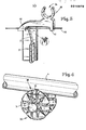
- Fig. 1, 1, 2 and 3 denote three cross members which extend across the length of a greenhouse and which are arranged on corresponding fixed stands. Wear these cross beams Push rods 4, 5, 6 and 7 which are displaceable transversely to their longitudinal axis and can be driven in a reciprocating movement aligned in their longitudinal axis via a central motor drive unit 8.
- heat insulation or shading materials 14 which connect with their other end to the cross bars 9 to 12 and can thus be moved from an accordion-like position to an extended position when the cross bars are moved and thereby cause shading.
- the large area shown can only be shaded with a motor drive unit 8 due to this arrangement described above.
- shading fabric 16 and 17 is provided, the shading fabric 16, for example, a shade of due to its design lo% and the shading fabric 17 causes, for example, a shading of 30%, ie is denser.
- the transverse rods 11a and 11b connected to these shading fabrics 16 and 17 have drivers 18 and 19 directed downwards.
- a drive plate 20 is arranged on the push rod 4, which has closed areas 25 and free passage areas 26, the rotary drive required for a rotary movement of the push rod 4 being recognizable at 21. With this rotary drive 21 formed from a toothed rack 27 and a toothed wheel 28, all the push rods 4, 5, 6 and 7 shown in FIG. 1 can be actuated with a single motor drive unit.
- Fig. 4 shows the example of the push rod 4 that the push rods are mounted on rollers that enable a rotary movement transversely to the longitudinal axis of the push rod and parallel to the longitudinal axis of the push rod, in that the rollers are rotatably mounted once about the axis 31 directed transversely to the longitudinal axis of the push rod and have roller bodies on their outer circumference 38 wear, which are fixedly connected to the impeller 30, but can rotate about axes 32 extending parallel to the longitudinal axis of the push rod.
- Components of this type can be produced inexpensively from plastic and enable the push rods to be stored safely and properly.
- individual drivers can of course also be provided, which are not disk-shaped but are capable of the one previously described on the driving disk 20 Function.
- a spring lock 34 is provided, which consists of a support plate which can be fixed via a clip 39, for example on the push rod 11a.
- a guide is provided in the area of the clip, directed downwards, which consists of two flanges 40 and 41 arranged at a distance from one another, through which a wire 36 is guided.
- On the underside of this wire there is a spring tongue 35 provided on a stationary bearing 37, the length of the spring tongue being somewhat greater than the distance from the wire 36 to the stationary bearing 37, so that when the wire 36 moves, the spring tongue 35 is above its dead center position must be pulled. In the position shown in Fig.
- the spring tongue 35 is such that a movement of the thermal insulation and shading materials carried by the wire 36 to the right is not possible, but the spring blocks this movement. If the wire is now pulled, the spring moves over its central position into a position which is opposite to the position shown in FIG. 3 and has the effect that a return movement of the wire is then also excluded.
- This spring lock 34 is easy to manufacture in plastic injection molding, so very inexpensive, but causes the thermal insulation and shading materials to be moved back and forth in their position once set, but ent again from this position without much effort can be removed.
- the spring tongue 35 can consist of metal.
- a further shading fabric 23 and a thermal insulation material 22 are provided beneath the push rod 4, the material 22 being able to have a high thermal insulation effect, while the shading fabric 23 effects 50% shading.
- Driving cams 18a and 19a are provided on the assigned crossbars 11c and 11d, which are directed upwards and can get into the path of the driving disk 20.
- the drive plate 20 also carries the drive 19 of the shading fabric 17 over a closed region 25 takes and now pulls this shading fabric with a higher shading effect in front of the glass surface.
Landscapes
- Life Sciences & Earth Sciences (AREA)
- Environmental Sciences (AREA)
- Curtains And Furnishings For Windows Or Doors (AREA)
- Transmission Devices (AREA)
- Greenhouses (AREA)
- Wing Frames And Configurations (AREA)
Priority Applications (1)
| Application Number | Priority Date | Filing Date | Title |
|---|---|---|---|
| AT86101108T ATE51998T1 (de) | 1985-09-23 | 1986-01-28 | Vorrichtung zum betreiben einer schattierungsbzw. waermedaemmanlage in gewaechshaeusern od.dgl. |
Applications Claiming Priority (4)
| Application Number | Priority Date | Filing Date | Title |
|---|---|---|---|
| DE3533836 | 1985-09-23 | ||
| DE3533836 | 1985-09-23 | ||
| DE19853540758 DE3540758A1 (de) | 1985-09-23 | 1985-11-16 | Vorrichtung zum betreiben einer schattierungs- bzw. waermedaemmanlage in gewaechshaeusern od. dgl. |
| DE3540758 | 1985-11-16 |
Publications (2)
| Publication Number | Publication Date |
|---|---|
| EP0216979A1 true EP0216979A1 (fr) | 1987-04-08 |
| EP0216979B1 EP0216979B1 (fr) | 1990-04-18 |
Family
ID=25836269
Family Applications (1)
| Application Number | Title | Priority Date | Filing Date |
|---|---|---|---|
| EP86101108A Expired - Lifetime EP0216979B1 (fr) | 1985-09-23 | 1986-01-28 | Dispositif pour ombrager respectivement tempérer la chaleur dans des serres ou analogues |
Country Status (3)
| Country | Link |
|---|---|
| EP (1) | EP0216979B1 (fr) |
| DE (2) | DE3540758A1 (fr) |
| DK (1) | DK341286A (fr) |
Cited By (2)
| Publication number | Priority date | Publication date | Assignee | Title |
|---|---|---|---|---|
| GR1000402B (el) * | 1990-07-03 | 1992-06-30 | Athanasios Tsianakas | Μηχανισμος θερμοκουρτινας για μεταλλικα θερμοκηπια. |
| FR2898119A1 (fr) * | 2006-03-06 | 2007-09-07 | Paul Riedel | Dispositif de support de toiles de protection par des cables paralleles introduits dans la toile prealablement plissee en accordeon et percee |
Families Citing this family (3)
| Publication number | Priority date | Publication date | Assignee | Title |
|---|---|---|---|---|
| DE3808686A1 (de) * | 1988-02-25 | 1989-09-07 | Felix Heescher Gmbh | Faltbare schattier-, waermedaemm- und/oder verdunklungsbahn |
| DE20206951U1 (de) | 2002-05-02 | 2002-08-14 | Lock, Frank, 88521 Ertingen | Zahnstangentrieb für ein zu bewegendes Element, insbesondere eine Energieschirmanordnung und/oder Schattierungsvorrichtung |
| GB2421520A (en) | 2004-12-21 | 2006-06-28 | Daniel Cutler | Moveable cover or awning |
Citations (3)
| Publication number | Priority date | Publication date | Assignee | Title |
|---|---|---|---|---|
| FR1586497A (fr) * | 1967-10-26 | 1970-02-20 | ||
| NL7908872A (nl) * | 1979-01-29 | 1980-07-31 | Petrus Leonardus Jozef Bom | Inrichting voor het afdekken van een teeltstrook in een warenhuis. |
| GB2088941A (en) * | 1980-11-26 | 1982-06-16 | Buting Peter Eric | Apparatus for Screening a Glasshouse |
Family Cites Families (1)
| Publication number | Priority date | Publication date | Assignee | Title |
|---|---|---|---|---|
| DE8132487U1 (de) * | 1981-11-06 | 1982-04-22 | Globisch, Rosemarie Veronika, 7060 Schorndorf | "zickzackfoermig faltbare bahn fuer den waerme- und/oder lichtschutz von gewaechshaeusern" |
-
1985
- 1985-11-16 DE DE19853540758 patent/DE3540758A1/de active Granted
-
1986
- 1986-01-28 EP EP86101108A patent/EP0216979B1/fr not_active Expired - Lifetime
- 1986-01-28 DE DE8686101108T patent/DE3670422D1/de not_active Expired - Lifetime
- 1986-07-18 DK DK341286A patent/DK341286A/da not_active Application Discontinuation
Patent Citations (3)
| Publication number | Priority date | Publication date | Assignee | Title |
|---|---|---|---|---|
| FR1586497A (fr) * | 1967-10-26 | 1970-02-20 | ||
| NL7908872A (nl) * | 1979-01-29 | 1980-07-31 | Petrus Leonardus Jozef Bom | Inrichting voor het afdekken van een teeltstrook in een warenhuis. |
| GB2088941A (en) * | 1980-11-26 | 1982-06-16 | Buting Peter Eric | Apparatus for Screening a Glasshouse |
Cited By (2)
| Publication number | Priority date | Publication date | Assignee | Title |
|---|---|---|---|---|
| GR1000402B (el) * | 1990-07-03 | 1992-06-30 | Athanasios Tsianakas | Μηχανισμος θερμοκουρτινας για μεταλλικα θερμοκηπια. |
| FR2898119A1 (fr) * | 2006-03-06 | 2007-09-07 | Paul Riedel | Dispositif de support de toiles de protection par des cables paralleles introduits dans la toile prealablement plissee en accordeon et percee |
Also Published As
| Publication number | Publication date |
|---|---|
| DK341286D0 (da) | 1986-07-18 |
| EP0216979B1 (fr) | 1990-04-18 |
| DE3670422D1 (de) | 1990-05-23 |
| DK341286A (da) | 1987-03-24 |
| DE3540758C2 (fr) | 1987-09-24 |
| DE3540758A1 (de) | 1987-04-02 |
Similar Documents
| Publication | Publication Date | Title |
|---|---|---|
| DE69912646T2 (de) | Einstellbare schiene zum fördern von produkten | |
| DE3443288C1 (de) | Elektromechanischer Antrieb fuer eine Zentralverriegelungsvorrichtung fuer Kraftfahrzeuge | |
| DE69812484T2 (de) | Verfahren und Vorrichtung zum Zusammenbau einer Kühlergrillblende eines Kraftfahrzeuges | |
| DE19928834B4 (de) | Stellvorrichtung für wenigstens drei Klappen einer Belüftungs-, Heizungs- oder Klimaanlage eines Kraftfahrzeuges | |
| DE2604882C2 (de) | Befahrbare Fläche für mechanische Parkeinrichtungen, Rampen, Hebebühnen o.dgl. | |
| DE2104050A1 (de) | Klemmhalterung | |
| DE3532150C1 (de) | Ausstell-Schiebedach fuer Kraftfahrzeuge | |
| EP0216979B1 (fr) | Dispositif pour ombrager respectivement tempérer la chaleur dans des serres ou analogues | |
| DE2450857A1 (de) | Schaltvorrichtung zur steuerung eines aufzuges | |
| DE3404541C2 (de) | Fahrzeugschiebedach | |
| DE2203269C3 (de) | Scheibenwaschanlage fur trapezförmige Scheiben | |
| DE202020104472U1 (de) | Vorrichtung zum Tragen von Bauteilen in einer Montagestraße | |
| DE1244610B (de) | Fensterstellvorrichtung fuer eine in Fuehrungen in einem Fensterschacht im wesentlichen lotrecht schiebbare und in ihm versenkbare Scheibe, vorzugsweise von Kraftfahrzeugen | |
| DE10316423B4 (de) | Getriebeaktor mit einer Lagerstelle für die Schaltschienen | |
| DE898858C (de) | Schaltgeraet fuer die Betaetigung beliebig vieler Regelorgane in gewaehlter Folge, insbesondere fuer Heizungs- und Belueftungsanlagen von Kraftfahrzeugen | |
| DE3136890A1 (de) | Motorbetaetigter fensterheber | |
| DE68903185T2 (de) | Stanzeinrichtung mit schwebender matrix. | |
| DE2839740C2 (de) | Schiebe-, Hebeschiebefenster oder -tür | |
| DE102018208956A1 (de) | Weichenvorrichtung | |
| DE2103739B2 (de) | Rechenreiniger mit elektromotorischem Antrieb einer parallel zum Rechen verfahrbaren und diesem gegenüber schwenkbaren Harke | |
| DE102018119944B4 (de) | Luftausströmer mit einer Bedieneinrichtung | |
| EP1451765B1 (fr) | Systeme d'entrainement pour au moins une unite receptacle de cartes a puces disposee dans un tachygraphe et permettant de placer une carte a puce en position de prelevement | |
| DE69210573T2 (de) | Abschneidescherenmechanismus für eine Glasformmaschine | |
| DE202019102900U1 (de) | Vorrichtung zum Vorschub von Waren | |
| DE102012211130A1 (de) | Bewegliche Trennwand |
Legal Events
| Date | Code | Title | Description |
|---|---|---|---|
| PUAI | Public reference made under article 153(3) epc to a published international application that has entered the european phase |
Free format text: ORIGINAL CODE: 0009012 |
|
| AK | Designated contracting states |
Kind code of ref document: A1 Designated state(s): AT BE CH DE FR GB LI NL SE |
|
| 17P | Request for examination filed |
Effective date: 19870825 |
|
| 17Q | First examination report despatched |
Effective date: 19890512 |
|
| GRAA | (expected) grant |
Free format text: ORIGINAL CODE: 0009210 |
|
| AK | Designated contracting states |
Kind code of ref document: B1 Designated state(s): AT BE CH DE FR GB LI NL SE |
|
| PG25 | Lapsed in a contracting state [announced via postgrant information from national office to epo] |
Ref country code: SE Effective date: 19900418 Ref country code: GB Effective date: 19900418 Ref country code: FR Effective date: 19900418 Ref country code: BE Effective date: 19900418 |
|
| REF | Corresponds to: |
Ref document number: 51998 Country of ref document: AT Date of ref document: 19900515 Kind code of ref document: T |
|
| REF | Corresponds to: |
Ref document number: 3670422 Country of ref document: DE Date of ref document: 19900523 |
|
| EN | Fr: translation not filed | ||
| GBV | Gb: ep patent (uk) treated as always having been void in accordance with gb section 77(7)/1977 [no translation filed] | ||
| PGFP | Annual fee paid to national office [announced via postgrant information from national office to epo] |
Ref country code: DE Payment date: 19901206 Year of fee payment: 6 |
|
| PG25 | Lapsed in a contracting state [announced via postgrant information from national office to epo] |
Ref country code: AT Effective date: 19910128 |
|
| PG25 | Lapsed in a contracting state [announced via postgrant information from national office to epo] |
Ref country code: LI Effective date: 19910131 Ref country code: CH Effective date: 19910131 |
|
| PLBE | No opposition filed within time limit |
Free format text: ORIGINAL CODE: 0009261 |
|
| STAA | Information on the status of an ep patent application or granted ep patent |
Free format text: STATUS: NO OPPOSITION FILED WITHIN TIME LIMIT |
|
| 26N | No opposition filed | ||
| PG25 | Lapsed in a contracting state [announced via postgrant information from national office to epo] |
Ref country code: NL Effective date: 19910801 |
|
| NLV4 | Nl: lapsed or anulled due to non-payment of the annual fee | ||
| REG | Reference to a national code |
Ref country code: CH Ref legal event code: PL |
|
| PG25 | Lapsed in a contracting state [announced via postgrant information from national office to epo] |
Ref country code: DE Effective date: 19921001 |