EP0217048A2 - Méthode d'édition d'un objet graphique dans un système graphique de dessin interactif - Google Patents
Méthode d'édition d'un objet graphique dans un système graphique de dessin interactif Download PDFInfo
- Publication number
- EP0217048A2 EP0217048A2 EP86110457A EP86110457A EP0217048A2 EP 0217048 A2 EP0217048 A2 EP 0217048A2 EP 86110457 A EP86110457 A EP 86110457A EP 86110457 A EP86110457 A EP 86110457A EP 0217048 A2 EP0217048 A2 EP 0217048A2
- Authority
- EP
- European Patent Office
- Prior art keywords
- sub
- editing
- graphic
- operator
- action
- Prior art date
- Legal status (The legal status is an assumption and is not a legal conclusion. Google has not performed a legal analysis and makes no representation as to the accuracy of the status listed.)
- Ceased
Links
Images


Classifications
-
- G—PHYSICS
- G06—COMPUTING OR CALCULATING; COUNTING
- G06T—IMAGE DATA PROCESSING OR GENERATION, IN GENERAL
- G06T11/00—Two-dimensional [2D] image generation
-
- G—PHYSICS
- G06—COMPUTING OR CALCULATING; COUNTING
- G06F—ELECTRIC DIGITAL DATA PROCESSING
- G06F3/00—Input arrangements for transferring data to be processed into a form capable of being handled by the computer; Output arrangements for transferring data from processing unit to output unit, e.g. interface arrangements
- G06F3/01—Input arrangements or combined input and output arrangements for interaction between user and computer
- G06F3/048—Interaction techniques based on graphical user interfaces [GUI]
- G06F3/0484—Interaction techniques based on graphical user interfaces [GUI] for the control of specific functions or operations, e.g. selecting or manipulating an object, an image or a displayed text element, setting a parameter value or selecting a range
- G06F3/04845—Interaction techniques based on graphical user interfaces [GUI] for the control of specific functions or operations, e.g. selecting or manipulating an object, an image or a displayed text element, setting a parameter value or selecting a range for image manipulation, e.g. dragging, rotation, expansion or change of colour
Definitions
- This invention relates in general to interactive draw graphic systems, and in particular, to an improved method of editing graphic objects in which the operator is allowed to pre-select the effect that an editing action on a sub-object will have on the whole object.
- the prior art has disclosed various interactive draw graphic arrangements in which a graphic object may be created and edited, e.g., modified by an operator following a sequence of interactions with the systems.
- These systems generally include an all-points addressable display device which functions to display on its screen, graphic object creating actions or editing actions that the operator has selected and entered into the system by means of a keyboard or a mouse.
- Interactive draw graphic systems may be physically packaged as a dedicated type stand-alone work station or as a group of separate, cable-connected personal computer system components that is executing a draw graphics program.
- sub-object refers to a part of a graphic object. This part or segment exists between two defined points which are included in the definition of the main object.
- the end points of the sub-object may or may not be connected to another segment. If the object is a closed object, then the end points of each sub-object are connected. If, on the other hand, the object is open, then at least one of the end points is not connected.
- a "joint" or a vertex is formed when two end points of different sub-objects are interconnected.
- the rubber-banding action occurs because the system has defined all of the sub-objects that define the main object as line segments between two points, each of which is represented by an x, y coordinate. If the point is moved by the editing action on a sub-object, the system redefines the end points for the sub-object and also for the attached line segments. If the operator merely wants to modify the appearance of the sub-object and not the total object, he must erase the sub-object and re-draw it. This is not very efficient from the operator standpoint and could be very frustrating if the sub-object is overlaid with a number of other graphic objects, since it is quite easy to erase the wrong lines in the erasing process.
- Co-pending U.S. application Serial No. 710 762 entitled "Method of Manipulation of Graphic Sub-Objects in an Interactive Draw Graphic System filed on March 11, 1985 and assigned to the assignee of the present invention is directed to a method in which the operator is provided with a choice of whether or not the entire object should be modified when a sub-object is being modified. That method involves the step of assigning a binary attribute to the end points of the sub-object to be modified that determine if each vertex corresponding to each end point of the sub-object can be "broken” or separated or whether it is to "stay attached.” If the operator chooses to have the vertices break, the operator controls which one or both vertices break by where along the length of the sub-object it is selected.
- both vertices break as the sub-object segment is moved. If, however, the sub-object is selected at either of its end third portions, then the sub-object is merely rotated around the opposite vertex. In either case, the remaining portion of the object is not affected. If the operator elects to have the vertices not break, but stay attached as the sub-object is moved, then any editing action on the sub-object affects the shape and appearance of the overall object, in that the line segments attached to the ends of the sub-object are redrawn by the system in a "rubber-banding" action.
- the first option when selected by the operator keeps the original shape of the object and only changes the edited sub-object.
- the second option alters the original shape of the object by re-drawing the segments that connect with the ends of the edited part, i.e., in a so-called "rubber-banding" action.
- the first option is referred to as "ASIS,” while the second option is referred to as "REDEFINE.”
- the operator either has the option to select whether the object should retain its original shape with only the part that has been edited changed, or whether the object should be re-defined by re-drawing the segments that originally connected to the ends of the edited sub-object.
- a further object of the present invention is to provide an improved method for editing a graphic sub-object in an interactive draw graphic system in which the operator can select whether the object containing the sub-object will be REDEFINED or stay ASIS as a result of the sub-object editing action.
- Fig. 1 illustrates the general arrangement of a typical interactive draw graphics system.
- the system shown comprises a display device 10 for displaying information to the operator, a keyboard 11 which the operator uses to enter information including commands and data into the system, a printer 13 which functions to provide hard copy output of information generated by the system and selected by the operator, a pair of diskette drives, 14L and 14R which function to transfer information between the system and the magnetic storage diskettes that are removably associated with the diskette drives and which store both program information, text information, and graphic information.
- System components 10, 11, 13, 14L, and 14R are connected, as shown in Fig. 1, to the microprocessor Block 15 which functions as the overall control for the system and interconnects the various system components to perform their specific function at the appropriate time.
- the system of Fig. 1 also includes a modem 16 which functions to interconnect that system to other systems through various communication links.
- auxiliary input device 18 is also provided for permitting more rapid positioning of the cursor on the screen than might be obtainable by the cursor positioning keys on the keyboard 11.
- Such devices are well known in the art, and for purposes of this description, it will be assumed that device 18 is a conventional "mouse" equipped with two buttons or keys, 18A and 18B. Devices such as a data tablet, having similar functions to the mouse, could also be employed for input device 18.
- Fig. 1 is provided with a suitable interactive draw graphic type program which permits the operator to draw graphics objects on the screen of device 10, similar to the objects shown in Fig. 2 which illustrates a display screen having rectangularly shaped objects 20, 22, and 24.
- This graphics editing mode can be set to ASIS or REDEFINE.
- the option is preferably established as one of the system defaults at the time the draw graphic program is initially installed in the system of Fig. 1 and provision is included in the program to enable that default to be changed at some subsequent time if the operator so desires.
- the current editing mode is ASIS
- the system manipulates the selected sub-object only without modifying the other parts of the original object.
- the current editing mode is REDEFINE, the system manipulates the selected sub-object and reconfigures the original objects so that the adjoining sides remain attached to the manipulated sub-object.
- the function of selecting the graphic object to be edited is not described, but that editing the sub-object is, by definition, a sub-set function of the main object editing function.
- the following description describes, in connection with Figs. 2, 3, 4, 5, and 6, the different results that occur for objects and depending on the action which is occurring and the graphic editing mode in effect.
- the selection of the sub-object is in accordance with the well known approach of positioning a pointing cursor adjacent the sub-object and operating either a mouse key or keyboard key, having the function of advising the system that the closest object is the one that is selected.
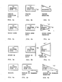
- Objects 20, 22, and 24 in Figs. 2a - 2c represent rectangles previously created by the operator using a cursor locating device.
- the locating device can be a mouse, keyboard, etc.
- Fig. 2 illustrates what happens when the operator selects the line segment 21 and applies the stretch action.
- object 22 since the editing mode is assigned to be ASIS, only the selected line segment 23 stretches and changes shape, leaving the remaining part of the object unaltered.
- line segment 25 remains attached to object 24, redefining the shape of the object 24. The entire object changes shape to keep up with the movement of the line segment 25, which results from the operator moving the mouse.
- Figs. 3, 4, 5, and 6 illustrate the results of applying various actions to sub-object 21 of object 20 with differing results depending on the current graphic editing mode.
- sub-object 33 is selected and the shrink function causes only side 33 to shrink the remaining portions of object 32 remains unaffected, since the ASIS option was selected.
- the object 34 is redrawn as a result of the SHRINK editing action on line 35 and the selection of the REDEFINE option.
- the SCALEDOWN editing action is applied to side 43 of object 42.
- the SCALEDOWN function operates to shrink the ends an equal amount whereas the shrink action of Fig. 3 requires a direction towards which the shrink action occurs.
- the sub-object 43 is the only line affected with the ASIS option in operation. However, as shown in Fig. 4c, both line segments 46 and 47 are redrawn when the REDEFINE option is in effect and sub-object 45 is scaled down.
- Figs. 5a - 5c are similar to 4a - 4c except that the SCALEUP editing action is depicted.
- the type of graphics editing mode in effect is initialized as shown in Block 70.
- the mode is the system default or the system default as changed by the operator after system initialization.
- Block 72 When the application detects that a mouse key has been pressed, a check is made to determine if the key is the Object Select Key as shown in Block 72. If the Object Select Key has been pressed, then the application checks to see if the pointer is within selecting range of any graphic object. This is shown in Block 73. If the application determines that the pointer is not close enough to any object to select, the application continues to read the locator device for operator input.
- the application determines if that object has already been selected, as shown in Block 74. If the object has not been selected, then the application highlights the object as shown in Block 75, and waits for further operator input. The operator, at this point, can do a range of actions on the object, but these are not the subject of this invention. If the selected object is already selected, then the operator is trying to select a portion of the object. Therefore, the segment pointed to by the locator device is highlighted and the rest of the object de-highlighted as shown in Block 76.
- the application must determine what graphics editing mode is in effect. If the ASIS editing mode is in effect, the selected sub-object is broken into two objects so that the sub-object can be manipulated independent of the rest of the object. This is shown in Block 77.
- the application carries out whatever action the operator had previously specified. The action to be performed is specified by the operator, either through implicit action editing or through a menu interface presented to the operator by the application. The action is applied until the operator terminates the action as shown in Block 79. If the REDEFINE editing mode is in effect, the action is performed on the segment as shown in Block 80.
- the application is also "rubber-banding" the adjoining segments to keep up with the movement of the sub-object as shown in Block 81.
- the action to be performed is specified by the operator, either through implicit action editing or through a menu interface presented to the operator by the application. Editing in this mode has the effect of changing the appearance of the entire object. The action is applied until the operator terminates the action as shown in Block 82.
- the application continues to monitor for operator input until the session is terminated as shown in Block. 83.
- FIG. 1 An illustration of an application program useable by the processor of Fig. 1 for causing a sub-object to be manipulated either ASIS or in a REDEFINE graphics editing mode during interactive graphics follows.
- This program is in program design language from which source and machine code are derivable. It is to be assumed that the system is under mouse and keyboard control. The mouse controls the movement of a visible pointing cursor which allows the operator to determine the current cursor position on the screen.
- the application calls a routine (CALL GET_MODE) to determine the current graphics editing mode prior to interactive graphics editing. Once the mode is determined, the application calls a routine to query the mouse input device to determine if a mouse key has been pressed (CALL READ_INPUT_DEVICE). READ_INPUT_DEVICE will return the selected mouse key and current X and Y location of the pointing cursor. If the OBJECT_SELECT_KEY is pressed, a routine is called (CALL FIND_OBJECT) to determine if the X and Y location returned from READ_INPUT_DEVICE is currently pointing to a graphic object, for example, a circle. If the operator was not pointing at any object, then the application returns to READ_INPUT_DEVICE to continue reading operator input.
- CALL FIND_OBJECT CALL FIND_OBJECT
- the application calls a routine to determine if the object is already selected by calling the function OBJECT_SELECTED. If the object is not already selected, the object is highlighted (CALL HIGHLIGHT_OBJECT). If the object is already selected, then the operator is trying to select part of the object, namely a segment. Therefore, the object must be de-highlighted (CALL DEHIGHLIGHT_OBJECT). The application then calls a routine (CALL FIND_SEGMENT) to get a handle on the segment being printed to, and a routine to highlight that segment (CALL HIGHLIGHT_OBJECT).
- the application determines which graphics editing mode is in effect (CASE G_EDIT_MODE). If the graphics editing mode is ASIS, a routine is called (CALL BREAK_OBJECT) to break the selected segment from the rest of the object in order to manipulate the segment independently. The application also calls a routine to determine the current active action (CALL GET_ACTION_TYPE). The application then continues to monitor for operator input (CALL READ_INPUT_DEVICE) and calls a routine to interactively edit the segment (CALL G_OBJECT_EDIT) according to the ACTION_TYPE parameter. This process is repeated until the editing of the segment is complete (UNTIL ACTION_COMPLETE).
- the application continues to monitor for operator input and calls a routine to interactively edit the segment (CALL G_SUBOBJECT_EDIT) according to the ACTION_TYPE parameter. Since the segment is still attached to the rest of the object, a routine is called (CALL G_RUBBERBAND) to rubber-band the adjoining segments as the segment is manipulated. This process is repeated until the editing of the segment is complete (UNTIL ACTION_COMPLETE).
Landscapes
- Engineering & Computer Science (AREA)
- Theoretical Computer Science (AREA)
- General Engineering & Computer Science (AREA)
- Physics & Mathematics (AREA)
- General Physics & Mathematics (AREA)
- Human Computer Interaction (AREA)
- Processing Or Creating Images (AREA)
Applications Claiming Priority (2)
| Application Number | Priority Date | Filing Date | Title |
|---|---|---|---|
| US781621 | 1985-09-30 | ||
| US06/781,621 US4703321A (en) | 1985-09-30 | 1985-09-30 | Method for editing a graphic object in an interactive draw graphic system |
Publications (2)
| Publication Number | Publication Date |
|---|---|
| EP0217048A2 true EP0217048A2 (fr) | 1987-04-08 |
| EP0217048A3 EP0217048A3 (fr) | 1990-08-01 |
Family
ID=25123361
Family Applications (1)
| Application Number | Title | Priority Date | Filing Date |
|---|---|---|---|
| EP86110457A Ceased EP0217048A3 (fr) | 1985-09-30 | 1986-07-29 | Méthode d'édition d'un objet graphique dans un système graphique de dessin interactif |
Country Status (4)
| Country | Link |
|---|---|
| US (1) | US4703321A (fr) |
| EP (1) | EP0217048A3 (fr) |
| JP (1) | JPS6275776A (fr) |
| BR (1) | BR8604719A (fr) |
Cited By (2)
| Publication number | Priority date | Publication date | Assignee | Title |
|---|---|---|---|---|
| EP0332712A4 (en) * | 1987-09-02 | 1992-12-02 | Fanuc Ltd | Method of correcting contour profile |
| EP0342240A4 (en) * | 1987-10-20 | 1992-12-16 | Fanuc Ltd | Method of correcting figure element |
Families Citing this family (16)
| Publication number | Priority date | Publication date | Assignee | Title |
|---|---|---|---|---|
| US4974194A (en) * | 1986-04-04 | 1990-11-27 | International Business Machines Corporation | Method for modifying intermingled text object and graphic object within an object set individually or correspondingly |
| US4829446A (en) * | 1986-12-12 | 1989-05-09 | Caeco, Inc. | Method and apparatus for recording and rearranging representations of objects in a model of a group of objects located using a co-ordinate system |
| US5285193A (en) * | 1987-01-16 | 1994-02-08 | Sharp Kabushiki Kaisha | Data base system |
| JP2689433B2 (ja) * | 1987-07-30 | 1997-12-10 | 株式会社日立製作所 | 図形描画方法および図形描画システム |
| GB8725033D0 (en) * | 1987-10-26 | 1987-12-02 | Crosfield Electronics Ltd | Interactive image display |
| JPH01234967A (ja) * | 1988-03-16 | 1989-09-20 | Hitachi Ltd | 文書作成装置 |
| GB2245807A (en) * | 1990-06-28 | 1992-01-08 | Rank Cintel Ltd | Editing of object-based animated computer graphics |
| JP2720586B2 (ja) * | 1990-07-27 | 1998-03-04 | 富士ゼロックス株式会社 | 図形編集装置 |
| US5276791A (en) * | 1991-01-29 | 1994-01-04 | International Business Machines Corporation | Network editing system |
| US6104396A (en) * | 1992-04-17 | 2000-08-15 | Matsushita Graphic Communication Systems Inc. | Information processing system |
| US5513309A (en) * | 1993-01-05 | 1996-04-30 | Apple Computer, Inc. | Graphic editor user interface for a pointer-based computer system |
| US5553224A (en) * | 1993-08-04 | 1996-09-03 | Xerox Corporation | Method for dynamically maintaining multiple structural interpretations in graphics system |
| US5715413A (en) * | 1996-06-25 | 1998-02-03 | International Business Machines Corporation | Dragging and dropping with an instantiation object |
| CN100507818C (zh) * | 2006-04-30 | 2009-07-01 | 国际商业机器公司 | 使用户能够在一个文档中选择多个对象的方法及装置 |
| JP6584076B2 (ja) * | 2015-01-28 | 2019-10-02 | キヤノン株式会社 | 情報処理装置、情報処理方法、コンピュータプログラム |
| JP7093690B2 (ja) * | 2018-07-05 | 2022-06-30 | フォルシアクラリオン・エレクトロニクス株式会社 | 情報制御装置、及び表示変更方法 |
Family Cites Families (6)
| Publication number | Priority date | Publication date | Assignee | Title |
|---|---|---|---|---|
| DK191176A (da) * | 1976-04-29 | 1977-12-16 | Sf Sten As | Betonbelegningssten og fremgangsmade til dens fremstilling |
| US4622545A (en) * | 1982-09-30 | 1986-11-11 | Apple Computer, Inc. | Method and apparatus for image compression and manipulation |
| US4555699A (en) * | 1983-01-10 | 1985-11-26 | Bancware, Inc. | Data-entry system |
| US4586036A (en) * | 1983-02-28 | 1986-04-29 | Advanced Computer Concepts, Inc. | Graphics display systems |
| US4559533A (en) * | 1983-11-03 | 1985-12-17 | Burroughs Corporation | Method of electronically moving portions of several different images on a CRT screen |
| US4683468A (en) * | 1985-03-11 | 1987-07-28 | International Business Machines Corp. | Method for manipulation of graphic sub-objects in an interactive draw graphic system |
-
1985
- 1985-09-30 US US06/781,621 patent/US4703321A/en not_active Expired - Lifetime
-
1986
- 1986-07-18 JP JP61168227A patent/JPS6275776A/ja active Granted
- 1986-07-29 EP EP86110457A patent/EP0217048A3/fr not_active Ceased
- 1986-09-30 BR BR8604719A patent/BR8604719A/pt not_active IP Right Cessation
Cited By (2)
| Publication number | Priority date | Publication date | Assignee | Title |
|---|---|---|---|---|
| EP0332712A4 (en) * | 1987-09-02 | 1992-12-02 | Fanuc Ltd | Method of correcting contour profile |
| EP0342240A4 (en) * | 1987-10-20 | 1992-12-16 | Fanuc Ltd | Method of correcting figure element |
Also Published As
| Publication number | Publication date |
|---|---|
| US4703321A (en) | 1987-10-27 |
| BR8604719A (pt) | 1987-06-23 |
| JPH0462100B2 (fr) | 1992-10-05 |
| EP0217048A3 (fr) | 1990-08-01 |
| JPS6275776A (ja) | 1987-04-07 |
Similar Documents
| Publication | Publication Date | Title |
|---|---|---|
| EP0194442B1 (fr) | Méthode pour manipuler des sous-objets graphiques dans un système graphique de dessin interactif | |
| US4703321A (en) | Method for editing a graphic object in an interactive draw graphic system | |
| US4686522A (en) | Method of editing graphic objects in an interactive draw graphic system using implicit editing actions | |
| CA2124604C (fr) | Methode et dispositif de traitement de donnees de modele resultantes pour produire une seconde image inscrustee dans une premiere image | |
| US5621871A (en) | Automated system and method for annotation using callouts | |
| EP0635808B1 (fr) | Méthode et appareil pour traiter le modèle de la structure de données sur une image pour produire une sortie perceptible par l'homme dans le contexte de l'image | |
| US5357603A (en) | Method and system for changing a shape type while maintaining existing graphic characteristics | |
| US5396590A (en) | Non-modal method and apparatus for manipulating graphical objects | |
| US5263134A (en) | Method and apparatus for controlling computer displays by using a two dimensional scroll palette | |
| US5467441A (en) | Method for operating on objects in a first image using an object-based model data structure to produce a second contextual image having added, replaced or deleted objects | |
| US5729704A (en) | User-directed method for operating on an object-based model data structure through a second contextual image | |
| US5425137A (en) | System and method for processing images using computer-implemented software objects representing lenses | |
| US5124693A (en) | Three dimensional graphic display with user defined vanishing point | |
| EP0199909A2 (fr) | Mise à jour de données de graphique d'affaires par édition du graphique | |
| EP0192022A2 (fr) | Méthode pour la rotation interactive d'objets graphiques affichés | |
| GB2237486A (en) | Method and apparatus for controlling computer displays by using a two dimensional scroll palette | |
| US5671380A (en) | Method and apparatus for creating a graphic using graphic icons | |
| JP3186241B2 (ja) | 図形編集装置 | |
| GB2284524A (en) | Graphic editing apparatus and method | |
| US5630040A (en) | Edit screen display control device to confirm data layout without switching to screen showing entire layout | |
| EP0220461A2 (fr) | Affichage graphique à trois dimensions avec point de fuite défini par l'utilisateur | |
| JP2851857B2 (ja) | 情報処理装置及びその方法 | |
| JP3246952B2 (ja) | Cad処理方法および装置 | |
| JPS62140171A (ja) | ドキユメントレイアウト編集方式 | |
| JPH05324423A (ja) | 図形処理装置 |
Legal Events
| Date | Code | Title | Description |
|---|---|---|---|
| PUAI | Public reference made under article 153(3) epc to a published international application that has entered the european phase |
Free format text: ORIGINAL CODE: 0009012 |
|
| AK | Designated contracting states |
Kind code of ref document: A2 Designated state(s): DE FR GB |
|
| 17P | Request for examination filed |
Effective date: 19870728 |
|
| PUAL | Search report despatched |
Free format text: ORIGINAL CODE: 0009013 |
|
| AK | Designated contracting states |
Kind code of ref document: A3 Designated state(s): DE FR GB |
|
| 17Q | First examination report despatched |
Effective date: 19911030 |
|
| STAA | Information on the status of an ep patent application or granted ep patent |
Free format text: STATUS: THE APPLICATION HAS BEEN REFUSED |
|
| 18R | Application refused |
Effective date: 19950925 |
|
| APAF | Appeal reference modified |
Free format text: ORIGINAL CODE: EPIDOSCREFNE |
|
| RIN1 | Information on inventor provided before grant (corrected) |
Inventor name: BARKER, BARBARA ANN Inventor name: HERNANDEZ, IRENE HERNANDEZ |