EP0217134A2 - Dispositif d'étanchéité pour arbre - Google Patents
Dispositif d'étanchéité pour arbre Download PDFInfo
- Publication number
- EP0217134A2 EP0217134A2 EP86111839A EP86111839A EP0217134A2 EP 0217134 A2 EP0217134 A2 EP 0217134A2 EP 86111839 A EP86111839 A EP 86111839A EP 86111839 A EP86111839 A EP 86111839A EP 0217134 A2 EP0217134 A2 EP 0217134A2
- Authority
- EP
- European Patent Office
- Prior art keywords
- sealing
- labyrinth
- lip
- liquid
- sealing lip
- Prior art date
- Legal status (The legal status is an assumption and is not a legal conclusion. Google has not performed a legal analysis and makes no representation as to the accuracy of the status listed.)
- Withdrawn
Links
Images
Classifications
-
- F—MECHANICAL ENGINEERING; LIGHTING; HEATING; WEAPONS; BLASTING
- F16—ENGINEERING ELEMENTS AND UNITS; GENERAL MEASURES FOR PRODUCING AND MAINTAINING EFFECTIVE FUNCTIONING OF MACHINES OR INSTALLATIONS; THERMAL INSULATION IN GENERAL
- F16J—PISTONS; CYLINDERS; SEALINGS
- F16J15/00—Sealings
- F16J15/54—Other sealings for rotating shafts
-
- F—MECHANICAL ENGINEERING; LIGHTING; HEATING; WEAPONS; BLASTING
- F16—ENGINEERING ELEMENTS AND UNITS; GENERAL MEASURES FOR PRODUCING AND MAINTAINING EFFECTIVE FUNCTIONING OF MACHINES OR INSTALLATIONS; THERMAL INSULATION IN GENERAL
- F16J—PISTONS; CYLINDERS; SEALINGS
- F16J15/00—Sealings
- F16J15/002—Sealings comprising at least two sealings in succession
- F16J15/004—Sealings comprising at least two sealings in succession forming of recuperation chamber for the leaking fluid
Definitions
- the invention relates to a shaft sealing system for sealing gas-liquid mixtures.
- gas-liquid mixtures such as in particular of air oil mixtures containing splashes of lubricating oil in crankshaft housings of internal combustion engines, consisting of a rotating elastomeric lip seal ring, the sealing lip of which is lifted preferably under the centrifugal force during the rotation, and a labyrinth sealing ring connected upstream on the gas-liquid side.
- elastomeric lip sealing rings are generally successfully used as shaft sealing rings for sealing against liquids or gases which may be under different pressures.
- gas-liquid mixtures such as air-oil mixtures
- the dust and dirt particles entrained in oil can deposit on the sealing lip and cause damage to the sealing lip with subsequent leaks.
- the lubricating oil contains higher proportions of solid combustion residue particles or the lubricating oil has become more viscous due to combustion processes, such components entrained by the lubricating oil splashes on the sealing lip can very quickly cause damage with subsequent leaks .
- crankshaft seals in diesel engines often fail after a relatively short runtime.
- an elastomeric lip seal ring with an axial elastomeric projection on the air side is known as a seal, which is made of a metal ring which rotates with the shaft and is approximately U-shaped in cross section over the projection and is non-contact bent protected sit.
- a seal which is made of a metal ring which rotates with the shaft and is approximately U-shaped in cross section over the projection and is non-contact bent protected sit.
- shaft sealing systems for oil-mist-lubricated gears consist of a rotating elastomeric lip seal ring and an oil filter ring connected upstream of the oil mist.
- the sealing lip acts as a standstill lock only at a standstill or at low circulation speeds, while at higher circulation speeds it stands out from the sealing point under centrifugal force.
- the oil filter ring itself, the oil becomes at higher speeds
- the oil droplets are separated under centrifugal force and the oil droplets return to the gear unit via radial channels in the housing.
- the sealing lip itself remains free of oil deposits with subsequent destruction.
- the present invention is therefore based on the object of creating a shaft sealing system with respect to gas-liquid mixtures, such as in particular with respect to air-lubricating oil mixtures in crankshaft housings of high-performance diesel engines, which have an improved sealing effect with increased operational safety against leakages with a substantially increased service life.
- the seal should also be used economically in series diesel engines.
- This task is accomplished with a shaft sealing system circumferential elastomeric lip seal ring and on the gas liquid side axially upstream labyrith seal ring, in which the labyrinth seal ring consists of rotating and stationary parts during operation, between which a gap is formed, through which the gas liquid mixture is passed with multiple radial and axial deflection, in which in the lip seal part of the sealing lip a liquid return device acting on the gas liquid side is connected upstream and in which at least one liquid return duct leading radially outwards to the gas liquid space is provided between the lip seal part and the labyrinth seal part.
- Gas liquid mixtures penetrating into the labyrinth from the gas liquid side are now set in rotation in the labyrinth with multiple deflections, the liquid, possibly containing solid particles, are separated under centrifugal force, the droplets are collected on the axial projections at the exit of the labyrinth or at the end of the labyrinth and from there transported back to the liquid space via the radial return channel.
- the end of the labyrinth gap is preferably formed by a projection leading radially outwards, the end of which is chamfered for better dripping or spinning off the liquid.
- a liquid recirculation device is connected upstream of the actual sealing lip, which is lifted from the "standing" shaft by centrifugal force after the idle speed has been exceeded.
- This consists of a thread that conveys to the gas liquid side, rotates during operation and interacts with a race.
- the thread is preferably made of elastomeric material, which is vulcanized together with the sealing lip on a housing ring.
- the threaded ribs preferably interact radially outwards with the race and thus remain fully effective at high speeds.
- the race as at the end of the labyrinth, can have an end which is chamfered and points radially outwards to the return duct, from which collected liquids drip off to the duct.
- a pump wire is preferred to avoid it Kung the sealing sleeve for radial movements of the space between the sealing sleeve and the race on the liquid return device side designed as small as possible.
- the space is preferably foamed with a polymer material so that only a narrow gap remains between the filling and the race or sealing lip.
- the invention thus creates a shaft sealing system for sealing against gas-liquid mixtures, which seals without loss over a long period of operation.
- lubricating oil mixtures in the crankshaft housings of high-performance diesel engines in which the lubricating oil has a higher proportion of solid combustion residues and / or a higher viscosity, can be effectively sealed over long operating times.
- the relatively wide channel formed by rotating and stationary parts in the labyrinth cannot become clogged and the sealing lip is protected from gushing, dirty oil splashes with additional measures.
- the constructive design also ensures loss-free return and reusability of the lubricating oil.
- the seal according to the invention also has a small axial and radial space and can be assembled centered on the shaft with set gaps prior to assembly, so that its use in series engines as a sealing cartridge is economical.
- seal according to the invention is preferably to be used for sealing crankshaft ends in crankshaft housings of high-performance diesel engines, it can also be used at other sealing points with similar problems, such as for sealing oil-lubricated transmission shafts or bearings.
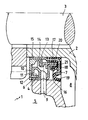
- the figure shows an embodiment of a shaft sealing system according to the invention in cross section.
- 1 is the shaft sealing system, which is firmly connected to the rotating crankshaft 3 of a diesel engine via the intermediate ring 2.
- the labyrinth part 4 has the opening 6 to the oil spray-filled crankshaft housing space 5, and the sealing lip part 7 is arranged on the air side 8. Between the labyrinth part 4 and the sealing lip part 7, the channel 9 leading radially outwards to the oil spray space 5 is arranged.
- a labyrinth gap 12 is formed in the labyrinth 4 by the part 10 rotating during operation and the stationary part 11, in which the oil spray mist is separated with multiple radial and axial deflection under the centrifugal force and separated and collected at the axial projections.
- the oil droplets return either into the crankshaft housing 5 via the opening 6 or via the radial rotating projection 13 with a beveled end 14 and the radial channel 9.
- the lip seal part 7 consists of the one with the crank Shaft 3 connected housing ring 15, on which the spring-loaded radially inwardly acting sealing lip 16, the spiral rdial outwardly acting return device 17 and an air-side protective lip 19 are vulcanized. Sealing lip 16 and return device 17 interact with the race 20, which is stationary during operation. In extreme cases, lubricant oil which has passed to the sealing lip part 7 is returned by the return device 17 in the direction of the labyrinth part 4 and drips from there via the beveled radial projection 23 of the race 20 for returning in the channel 9.
- the second radial projection 24 of the race 20 is used for centering and adjusting the gap when assembling the sealing ring 1 to form a mountable sealing cartridge.
- the housing ring 15, the race part 20 in the sealing lip part 7 and the stationary part 11 in the labyrinth 4 consist of metal, while the race 20 itself and the rotating part 10 in the labyrinth 4 consist of a plastic, such as polyamide or PVC.
- the space 18 between the sealing collar 16 and the race 20 is filled with polymer material while leaving the narrow gap 21, so that pumping effects due to radial displacements of the sealing collar 16 are largely excluded.
Landscapes
- Engineering & Computer Science (AREA)
- General Engineering & Computer Science (AREA)
- Mechanical Engineering (AREA)
- Sealing Using Fluids, Sealing Without Contact, And Removal Of Oil (AREA)
- Sealing With Elastic Sealing Lips (AREA)
- Sealing Of Bearings (AREA)
Applications Claiming Priority (2)
| Application Number | Priority Date | Filing Date | Title |
|---|---|---|---|
| DE19853535445 DE3535445A1 (de) | 1985-10-04 | 1985-10-04 | Wellenabdichtungssystem |
| DE3535445 | 1985-10-04 |
Publications (2)
| Publication Number | Publication Date |
|---|---|
| EP0217134A2 true EP0217134A2 (fr) | 1987-04-08 |
| EP0217134A3 EP0217134A3 (fr) | 1988-08-03 |
Family
ID=6282750
Family Applications (1)
| Application Number | Title | Priority Date | Filing Date |
|---|---|---|---|
| EP86111839A Withdrawn EP0217134A3 (fr) | 1985-10-04 | 1986-08-27 | Dispositif d'étanchéité pour arbre |
Country Status (5)
| Country | Link |
|---|---|
| US (1) | US4667967A (fr) |
| EP (1) | EP0217134A3 (fr) |
| JP (1) | JPS6283562A (fr) |
| DE (1) | DE3535445A1 (fr) |
| ES (1) | ES2003127A6 (fr) |
Cited By (1)
| Publication number | Priority date | Publication date | Assignee | Title |
|---|---|---|---|---|
| EP0317867A1 (fr) * | 1987-11-25 | 1989-05-31 | Siemens Aktiengesellschaft | Agencement de joint de labyrinthe |
Families Citing this family (28)
| Publication number | Priority date | Publication date | Assignee | Title |
|---|---|---|---|---|
| US4898134A (en) * | 1989-02-27 | 1990-02-06 | Outboard Marine Corporation | Crankcase seal arrangement for two cycle engine |
| US4976444A (en) * | 1989-08-21 | 1990-12-11 | Amoco Corporation | Seal and seal assembly |
| DE3930280A1 (de) * | 1989-09-11 | 1991-03-28 | Skf Gmbh | Beruehrungslose dichtung |
| US5228700A (en) * | 1989-09-11 | 1993-07-20 | Skf Gmbh | Contactless seal |
| US5201529A (en) * | 1990-02-16 | 1993-04-13 | Nok Corporation | Sealing device |
| DE4008264A1 (de) * | 1990-03-15 | 1991-09-19 | Goetze Ag | Wellenabdichtung |
| US5301957A (en) * | 1992-04-27 | 1994-04-12 | General Electric Company | Expanding circumferential seal with upper-cooled runner |
| AU4863093A (en) * | 1992-10-08 | 1994-04-21 | Ferrofluidics Corporation | Ferrofluidic seal centering ring |
| US5967524A (en) * | 1993-05-21 | 1999-10-19 | Jm Clipper Corporation | Hybrid seal device |
| US6017037A (en) * | 1993-05-21 | 2000-01-25 | J.M. Clipper Corporation | Seal device |
| US5735530A (en) | 1993-05-21 | 1998-04-07 | Jm Clipper Corporation | Seal device |
| US6065755A (en) * | 1993-05-21 | 2000-05-23 | Jm Clipper Corporation | Seal device |
| US5316317A (en) * | 1993-05-21 | 1994-05-31 | Jm Clipper Corporation | Method of assembling a seal device |
| US6170832B1 (en) | 1998-03-26 | 2001-01-09 | Hermann H. F. Ernst | Fluid ring seal system and method |
| DE19844417C1 (de) * | 1998-09-28 | 2000-05-11 | Siemens Ag | Gehäusegestaltung zur Abdichtung eines Zahnradschutz- oder Getriebekastens |
| US6726214B2 (en) | 1998-11-25 | 2004-04-27 | Jm Clipper Corporation | Wrap-around severe splash seal |
| US6336637B1 (en) | 1998-11-25 | 2002-01-08 | Jm Clipper Corporation | Sever splash seal |
| JP2001304278A (ja) | 1999-10-08 | 2001-10-31 | Nsk Ltd | 密封形軸受装置 |
| DE10003772A1 (de) * | 2000-01-28 | 2001-08-09 | Bosch Gmbh Robert | Vorrichtung zum Abdichten eines Raums |
| DE10004265A1 (de) | 2000-02-01 | 2001-08-09 | Lenze Gmbh & Co Kg Aerzen | Dichtsystem zwischen einer Welle und einem feststehenden Gehäuseteil |
| US6471211B1 (en) * | 2000-08-28 | 2002-10-29 | Brenco, Incorporated | Seal assembly |
| DE50100640D1 (de) * | 2000-09-12 | 2003-10-23 | Coperion Buss Ag Pratteln | Dichtungsanordnung |
| US6802511B1 (en) * | 2003-02-12 | 2004-10-12 | Morgan Construction Company | Seal end plate |
| ES2294885B1 (es) * | 2005-04-15 | 2009-03-16 | GAMESA INNOVATION & TECHNOLOGY, S.L. | Junta estanca para una multiplicadora. |
| US10844960B2 (en) * | 2018-12-04 | 2020-11-24 | Caterpillar Inc. | Crankshaft seal design |
| EP4043760A1 (fr) | 2021-02-12 | 2022-08-17 | Flender GmbH | Agencement d'étanchéité, ensemble carter, engrenage, application industrielle et produit programme informatique |
| CN114483959B (zh) * | 2022-03-27 | 2024-07-16 | 铁岭五星密封研究所有限公司 | 用于轧机轧辊辊轴油膜轴承的密封装置 |
| CN114894381B (zh) * | 2022-04-19 | 2025-05-16 | 长春通视光电技术有限公司 | 视频线气密试验工装 |
Family Cites Families (12)
| Publication number | Priority date | Publication date | Assignee | Title |
|---|---|---|---|---|
| US2994571A (en) * | 1957-03-05 | 1961-08-01 | Renault | Piston and rod packings |
| US3459431A (en) * | 1967-03-13 | 1969-08-05 | Patrick W Baker | Oil seal-dust shield assembly |
| DE2121816A1 (de) * | 1971-05-03 | 1972-11-16 | Gelenkwellenbau Gmbh, 4300 Essen | Abdichtung für ein Wälzlager |
| US3832021A (en) * | 1972-11-16 | 1974-08-27 | Morgan Construction Co | Neck seal |
| AT340216B (de) * | 1973-06-22 | 1977-12-12 | Burgmann Dichtungswerk Feodor | Dichtungsanordnung |
| DE2861253D1 (en) * | 1978-12-15 | 1981-12-10 | Freudenberg Carl Fa | Sealing for a gap between a rotating shaft and a crank case bore against a mixture of fluid and gas |
| IT1106716B (it) * | 1978-12-20 | 1985-11-18 | Dugomrulli Srl | Dispositivo di tenuta in particolare per testate di rulli per trasportatori |
| DE7935867U1 (de) * | 1979-12-20 | 1980-03-27 | Fag Kugelfischer Georg Schaefer & Co, 8720 Schweinfurt | Abgedichtetes Wälzlager |
| US4384387A (en) * | 1980-12-10 | 1983-05-24 | Jervis B. Webb Company | Conveyor trolley assembly with moisture-resistant bearing seal |
| US4383720A (en) * | 1982-01-29 | 1983-05-17 | Ernst Hermann H F | Centrifugal fluid seal |
| EP0117267B1 (fr) * | 1983-02-26 | 1986-08-27 | Firma Carl Freudenberg | Bague d'étanchéité |
| DE3534130A1 (de) * | 1985-09-25 | 1987-04-02 | Kaco Gmbh Co | Radialwellendichtung fuer ein lager, vorzugsweise ein waelzlager |
-
1985
- 1985-10-04 DE DE19853535445 patent/DE3535445A1/de active Granted
-
1986
- 1986-08-27 EP EP86111839A patent/EP0217134A3/fr not_active Withdrawn
- 1986-09-26 JP JP61226356A patent/JPS6283562A/ja active Pending
- 1986-10-03 ES ES8602400A patent/ES2003127A6/es not_active Expired
- 1986-10-03 US US06/915,127 patent/US4667967A/en not_active Expired - Fee Related
Cited By (1)
| Publication number | Priority date | Publication date | Assignee | Title |
|---|---|---|---|---|
| EP0317867A1 (fr) * | 1987-11-25 | 1989-05-31 | Siemens Aktiengesellschaft | Agencement de joint de labyrinthe |
Also Published As
| Publication number | Publication date |
|---|---|
| ES2003127A6 (es) | 1988-10-16 |
| JPS6283562A (ja) | 1987-04-17 |
| EP0217134A3 (fr) | 1988-08-03 |
| DE3535445C2 (fr) | 1988-05-19 |
| US4667967A (en) | 1987-05-26 |
| DE3535445A1 (de) | 1987-04-16 |
Similar Documents
| Publication | Publication Date | Title |
|---|---|---|
| EP0217134A2 (fr) | Dispositif d'étanchéité pour arbre | |
| DE2325614C2 (de) | Notsystem zur Zuführung eines Schmiermittels | |
| DE3005943C2 (fr) | ||
| EP2557315B1 (fr) | Palier à roulement et pompe à vide dotée d'un palier à roulement | |
| EP1476661B1 (fr) | Pompe a vide | |
| DE29807796U1 (de) | Dichtungsanordnung für einen Wellenzapfen eines trockenlaufenden Rotationsschraubenverdichters | |
| DE102010052310A1 (de) | Wellenanordnung | |
| DE1236855C2 (de) | OElabdichtung fuer Turbolader od. dgl. | |
| DE10310062A1 (de) | Öldichtung | |
| DE10122440B4 (de) | Anordnung mit einem einem Wellenlager zugeordneten Abschleuderring und einer einem Dichtspalt zugeordneten Dichtung | |
| DE4012361A1 (de) | Oeldichtungsvorrichtung fuer einen turbolader | |
| DE102013002490B3 (de) | Dichtungsanordnung zum berührungsfreien Abdichten von Wälzlagern | |
| DE602004003738T2 (de) | Wasserpumpe für Dieselmotor mit Öldichtung | |
| EP2431613A2 (fr) | Joint d'arbre pour une pompe à vide | |
| DE4131164A1 (de) | Vorrichtung zur lagerschmierung | |
| DE3320086A1 (de) | Lager-schmiereinrichtung | |
| DE102010044427A1 (de) | Wellendichtung | |
| DE3324468A1 (de) | Abgedichtetes waelzlager, insbesondere fuer wasserpumpen in kraftfahrzeugen | |
| DE102013224596A1 (de) | Lager und Verfahren | |
| DE3902058A1 (de) | Wellenabdichtungssystem | |
| DE19950705B4 (de) | Gas-Gleitringdichtung | |
| DE102020120268B3 (de) | Verbrennungsmotor | |
| DE19849237C2 (de) | Dichtsystem für eine aus Motor und Getriebe bestehende Antriebseinheit | |
| DE9002218U1 (de) | Wälzlager, insbesondere Getriebelager | |
| DE102021209885A1 (de) | Planetenradsatz und Getriebe für ein Kraftfahrzeug |
Legal Events
| Date | Code | Title | Description |
|---|---|---|---|
| PUAI | Public reference made under article 153(3) epc to a published international application that has entered the european phase |
Free format text: ORIGINAL CODE: 0009012 |
|
| AK | Designated contracting states |
Kind code of ref document: A2 Designated state(s): AT DE FR GB IT SE |
|
| PUAL | Search report despatched |
Free format text: ORIGINAL CODE: 0009013 |
|
| AK | Designated contracting states |
Kind code of ref document: A3 Designated state(s): AT DE FR GB IT SE |
|
| 17P | Request for examination filed |
Effective date: 19890112 |
|
| 17Q | First examination report despatched |
Effective date: 19891006 |
|
| STAA | Information on the status of an ep patent application or granted ep patent |
Free format text: STATUS: THE APPLICATION IS DEEMED TO BE WITHDRAWN |
|
| 18D | Application deemed to be withdrawn |
Effective date: 19900221 |
|
| RIN1 | Information on inventor provided before grant (corrected) |
Inventor name: DEURING, HANS, DIPL.-ING. |