EP0217161A1 - Dispositif pour guider des constructions intérieures électriques par barres de guidage en matière plastique - Google Patents
Dispositif pour guider des constructions intérieures électriques par barres de guidage en matière plastique Download PDFInfo
- Publication number
- EP0217161A1 EP0217161A1 EP86112159A EP86112159A EP0217161A1 EP 0217161 A1 EP0217161 A1 EP 0217161A1 EP 86112159 A EP86112159 A EP 86112159A EP 86112159 A EP86112159 A EP 86112159A EP 0217161 A1 EP0217161 A1 EP 0217161A1
- Authority
- EP
- European Patent Office
- Prior art keywords
- guide rails
- rails
- guide
- grid
- profile
- Prior art date
- Legal status (The legal status is an assumption and is not a legal conclusion. Google has not performed a legal analysis and makes no representation as to the accuracy of the status listed.)
- Granted
Links
- 238000010276 construction Methods 0.000 title description 3
- 238000009434 installation Methods 0.000 claims description 10
- 238000003780 insertion Methods 0.000 claims description 3
- 230000037431 insertion Effects 0.000 claims description 3
- 230000000284 resting effect Effects 0.000 claims description 2
- 230000000712 assembly Effects 0.000 abstract description 7
- 238000000429 assembly Methods 0.000 abstract description 7
- 238000001816 cooling Methods 0.000 description 5
- 238000010521 absorption reaction Methods 0.000 description 1
- XAGFODPZIPBFFR-UHFFFAOYSA-N aluminium Chemical compound [Al] XAGFODPZIPBFFR-UHFFFAOYSA-N 0.000 description 1
- 229910052782 aluminium Inorganic materials 0.000 description 1
- 238000006073 displacement reaction Methods 0.000 description 1
- 238000010616 electrical installation Methods 0.000 description 1
- 238000005516 engineering process Methods 0.000 description 1
- 230000017525 heat dissipation Effects 0.000 description 1
- 238000000034 method Methods 0.000 description 1
- 238000007789 sealing Methods 0.000 description 1
- XLYOFNOQVPJJNP-UHFFFAOYSA-N water Substances O XLYOFNOQVPJJNP-UHFFFAOYSA-N 0.000 description 1
- 238000003466 welding Methods 0.000 description 1
Images

Classifications
-
- H—ELECTRICITY
- H05—ELECTRIC TECHNIQUES NOT OTHERWISE PROVIDED FOR
- H05K—PRINTED CIRCUITS; CASINGS OR CONSTRUCTIONAL DETAILS OF ELECTRIC APPARATUS; MANUFACTURE OF ASSEMBLAGES OF ELECTRICAL COMPONENTS
- H05K7/00—Constructional details common to different types of electric apparatus
- H05K7/14—Mounting supporting structure in casing or on frame or rack
- H05K7/1417—Mounting supporting structure in casing or on frame or rack having securing means for mounting boards, plates or wiring boards
- H05K7/1418—Card guides, e.g. grooves
Definitions
- the invention relates to a device for guiding internal electrical installations, e.g. Printed circuit boards, plug-in modules or plug-in units, on a profile carrier plate, with at least two parallel and vertically superimposed, made of elastic plastic and provided with a guide groove for the internal fittings, which are symmetrical with respect to a length bisecting their length and on which the profile Carrier plate facing underside are formed with two oppositely directed snap-in hooks, each of which engages in a groove of the profile carrier plate, and with at least two grid rails which have a pitch grid, are parallel and run perpendicular to the guide rails.
- a device for guiding internal electrical installations e.g. Printed circuit boards, plug-in modules or plug-in units
- a profile carrier plate with at least two parallel and vertically superimposed, made of elastic plastic and provided with a guide groove for the internal fittings, which are symmetrical with respect to a length bisecting their length and on which the profile Carrier plate facing underside are formed with two oppositely
- Guide rails with a guide groove for inserting or inserting the internal components are often used to install electrical internal components, such as printed circuit boards, plug-in modules or plug-in modules, in slide-in modules or subracks, for example in housings for electrical devices.
- electrical internal components such as printed circuit boards, plug-in modules or plug-in modules, in slide-in modules or subracks, for example in housings for electrical devices.
- grid rails are used which are designed with a division grid into which the Engage the guide rails with locking devices.
- Such grid and guide rails are known in a variety of embodiments.
- a module carrier consisting of a profile carrier plate with guide strips and two locking rails for printed circuit boards
- the guide strips provided with a guide groove are constructed symmetrically with respect to a plane bisecting their length and facing the profile carrier plate
- Underside with two oppositely directed hook-shaped locking lugs are formed, which engage in grooves of the profile support plate, in which the locking rails are arranged under the guide rails.
- These known guide strips are themselves held without screws by snapping into the profile on the profile carrier plate, but do not offer any possibility of securely holding the circuit boards in the guide groove, i.e. the circuit boards are not secured against being pulled out.
- the known subrack there are also no means for wiring the printed circuit boards to one another and are therefore not included in the guidance and assembly system of the printed circuit boards. This means that any wiring means to be provided would have to be attached and fastened separately in the subrack.
- DE-PS 1 271 793 specifies a device unit for receiving plug-in modules which has guide rails made of elastic plastic. Due to their symmetrical design and the hook-shaped locking lugs laterally offset from the guide groove, the guide rails can be inserted into the pitch grid of the profiled mounting plate in such a way that two guide rails offset by half a grid step can be rotated by rotating a guide rail by 180 ° I and II were possible.
- the spring strips assigned to the plug-in modules are also held jammed against the carrier.
- a rack for receiving insertable electrical modules with guide and grid rails is known, the grid rails, two of which are horizontally parallel, are arranged on one or more lines and the guide rails are latched into the grid rails below are.
- a wiring field in the form of an etched printed circuit board is provided on the back of the subrack and covers the entire back of the subrack.
- the wiring field is attached to the ends of the guide rails using screw or snap connections.
- the guide rails are either cut straight vertically at their rear end and provided with a bore for receiving the screws or with locking pins which, if necessary, engage in corresponding recesses within the printed circuit board of the wiring field.
- the wiring field and its attachment are included in the guide system.
- the wiring field can be easily installed and removed without having to loosen or remove other components of the subrack.
- this too Subracks each require two grid rails and these are arranged under the guide rails, the modules are only inserted into the guide rails and are not secured in them against being pulled out.
- the guide rails cannot be inserted into the subrack on a fold.
- This bracket consists essentially of support strips with a sawtooth-shaped L-profile, which form grid rails and guide rails with a guide groove for inserting the circuit boards.
- the guide rails cooperate at one end with the grid rails and for this purpose are T-shaped and provided with a U-shaped bracket. This grips the L-profile of the support strips.
- the guide rails At the other end, which cooperates with a rear wall, the guide rails have a double spring pawl which engage in the rear wall which serves to electrically connect the printed circuit boards to one another.
- the grid rails and the rear wall serve at the same time as support elements for the guide rails, separate latching or holding means for the guide rails are thus not provided.
- the mounting of the guide rails is therefore only possible if the rear wall and grid rails are already firmly in place. This is a considerable disadvantage not only when installing, but also when replacing.
- the circuit boards are also not secured against being pulled out of the guide rails and the guide rails are asymmetrical.
- a plastic guide rail for printed circuit boards which has a snap connector at one end, which in one Housing frame snaps into place, while at the other end there is at least one pin which extends further as an extension on the end face in the longitudinal direction of the guide rail and which engages in corresponding bores on the rear of the housing frame or on a printed circuit board fastened to the rear of the housing frame.
- the guide rail is asymmetrical and has as its own holding means only the snap connector and the end pins, so that a rear wall or a circuit board attached to the rear wall of the housing frame is absolutely necessary for fixing a guide rail.
- no grid rail is provided in the known arrangement.
- DE-AS 1 119 920 shows a slide-in rack for receiving component-carrying slide-ins with raster rails formed by several rows of slots in the slide-in rack and hooked therein guide rails which are designed with hooks, locking and guide lugs and in the hooked position with their rear end the associated female connector hold both in place against the slide-in support and immovable to the side.
- Wiring means are not provided in the known insert carrier.
- the plastic guide rails are formed approximately in the middle of their length with cam springs which engage in recesses in the plate-shaped inserts and secure them in their inserted position. When loosening an insert, however, it is therefore necessary that the guide rails remain accessible in the area of the cam springs.
- the guide rails are asymmetrical, so that they can only be inserted into the rows of slots in one direction.
- DE-PS 23 48 492 there is also a tool for pulling plug-in modules arranged in guide rails which, in the plug-in end position, engage with latching edges arranged in the region of the operating front on a resilient latching hook which is provided at the beginning of the guide rail on a spring arm and protrudes into the guide groove in the relaxed position. In this way, plug-in modules can be secured against being pulled out of the guide rails.
- guide rails show that it is known to design guide rails in such a way that they can be easily fixed even by snapping in, by means of training with cam springs or resilient latching hooks to secure printed circuit boards, plug-in modules or inserts against being pulled out, and can be used by symmetrical training on the envelope or engage at one end with locking means in a common wiring field. Nevertheless, no guide rail has all of these properties at the same time, so that at least one of the disadvantages described must always be accepted when using the known guide rails.
- the invention is therefore based on the object to provide a device for guiding electrical internals on a profile carrier plate, which allows a completely tool-free installation of the plastic guide rails themselves as well as the internals that can be inserted into the guide rails and a common wiring plate incorporated in the guide system with secure fixation of the individual components.
- the plastic guide rails which are constructed completely symmetrically with respect to a plane bisecting their length, are designed in such a way that they snap in, in a first position as well as when they are turned, ie after a rotation through 180 ° Locking can be used both in the profiling of the carrier plate and in the grid rails and in the wiring plate.
- the rotation by 180 ° enables halving of the grid. It is for several in one level on one Profile support plate arranged guide rails only require a grid rail, since the function of a second grid rail is performed by the wiring plate provided with corresponding recesses.
- This wiring plate can be fixed to the carrier plate by latching two guide rails arranged in parallel one above the other, for example on the bottom and top plates of a housing, in that only the centering hook is suspended in the wiring plate at the relevant end of the guide rails already inserted in the profiling of the carrier plate becomes.
- the wiring plate integrated in this way into the assembly and guide system for the internal installations can then be removed again without further notice, without loosening or removing the guide rails or other components.
- the guide groove of the guide rails is formed with two further spring arms in the course of their longitudinal extension, which have at their free end a nose which projects into the guide groove in the relaxed state. This ensures that the internals are firmly pressed against a side wall of the guide groove even in the course of the longitudinal extension and are thus held in the guide rails without rattling noises.
- the guide rails are formed at the free end of the further spring arms each with a recess into which a further wiring plate can be inserted in an intermediate plane.
- the further wiring plates are provided with a recess in such a way that the wiring plates in the region of their recess closely enclose the cross section of the guide rail in the region of the recesses at the free ends of a further spring arm. In this way, additional wiring boards can easily be held on the profile support plate.
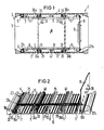
- the housing 1 in Fig. 1 has a box-shaped frame or casing 2, which consists of two mutually opposite central parts, namely a base plate 3 and a cover plate 4, and two side walls tightly connected to it, of which only the side wall 5 in Fig.1 see is there.
- the housing jacket can be sealed with a screw-on or fold-down front plate and a rear wall, both of which are not shown.
- the water and HF tightness of the housing can be ensured by the fact that the middle parts and the side walls are tightly connected at the four edges by suitable welding processes and a combined rubber-wire sealing cord is inserted into a groove in the front panel and the rear wall.
- the housing is designed in its basic structure, such as the housing series described in DE-AS 25 23 292, DE-PS 25 38 314 and DE-PS 24 43 122 and known under the trademark "SIDISET", whereby for the existing housing, if necessary, individual parts, such as the front panel and the rear wall, can be used from the known system.
- the middle parts 3, 4 which carry the internal installations, such as, for example, printed circuit boards, plug-in modules or plug-in units, are each composed of a profile carrier plate Extruded aluminum profile with a plate edge that is opposed to two opposite sides, here parallel to the front and rear profile profile in the direction of the housing width.
- FIG. 2 shows a section of a central part 3 forming the base plate 3 and designed as a profile support plate 10.
- the central part forming the cover plate 4 is - as can be seen in FIG. 1 - designed in the same way and therefore not shown in more detail in FIG.
- the device in the present case thus consists of two middle parts 3 and 4, that is, two profile support plates 10, which are formed with two parallel, vertically superimposed grid rails 6 and a plurality of pairs of mutually parallel and perpendicular to the grid rails guide rails 7, so that A circuit board or a plug-in module, for example, can be inserted into the housing 1 between a lower and a vertically directly above guide rail.
- a common wiring board 8 is provided for wiring the printed circuit boards or plug-in assemblies to one another, the wiring board - like the printed circuit boards or plug-in assemblies - being designed with a plug connector 9, for example consisting of an etched printed circuit board, and extending over the entire rear side of the housing shell 2 can.
- the profile carrier plate 10 has a regular profile profile with profile ribs 11 and cooling ribs 12 evenly distributed within the area receiving the internals.
- profile carrier plate 10 has a regular profile profile with profile ribs 11 and cooling ribs 12 evenly distributed within the area receiving the internals.
- five profile ribs 11 are provided, which are arranged at the same distance from one another and run parallel to two opposite plate edges, i.e. to the front and back, and to each other.
- Four cooling ribs 12 are provided between each two profile ribs 11, which are arranged at the same distance from one another and run parallel to the profile ribs and to one another.
- the profile ribs 11 consist of a web 13 perpendicular to the level of the profile support plate 10 and a C-profile rail 14 arranged on this web with an open T-groove 15 towards the internal fittings, the C-profile rail 14 on both vertical sides of the Extends web and is arranged here symmetrically with respect to a line of symmetry of the web extending in the longitudinal direction of the profile rib 11.
- the internals can be screwless - if necessary, they can also be screwed using a sliding or Sliding nuts - with the help of the guide rails 7 to be held by snapping or snapping into the C-profile rails 14 at any point on the profile carrier plate.
- This means that the C-profile rails also form assembly rails that enable the use of snap-in assembly technology for the housing internals or their guiding and locking means.
- the profile carrier plate 10 is outside of the area receiving the internals between the two outermost profile ribs 11 and the respective edge of the carrier plate on the front or rear of the housing with a groove 16a open towards the internals or 16b.
- This groove is T-shaped on the one hand by the outer shoulder, forming an undercut 17, of the corresponding C-profile rail 14 of the outermost profile rib 11 and, on the other hand, by an opposite undercut 18 of the carrier plate 10 and has a rib 19 approximately in its center, which compared to the cooling fins 12 is slightly lower.
- the groove 16a located near the front of the housing serves to insert the grid rail 6 formed with a pitch grid, while in the groove 16b located near the rear of the housing, the common wiring plate 8 is perpendicular to the carrier plate and to the direction of insertion of the internals and optionally on the C-profile rail 14 of the other outermost profile rib 11 is inserted adjacent.
- the grid rail 6 consists of a cross-sectionally U-shaped plastic part, the legs 20 of which are spread slightly outwards so that they enclose an angle of somewhat more than 90 ° with the central part 21 having the division grid.
- the legs 20 of the grid rail 6 are provided at their free end with outwardly directed barbs 22. This means that the opening is correspondingly dimensioned from above Niert groove 16a insertable and with their length of the housing width corresponding grid rail 6 can be fixed by clamping in the groove.
- the division grid on the central part 21 of the grid rail 6 consists of a perforated grid which is formed by a plurality of oblong hole-like recesses 23 which extend transversely to the groove 16a in the direction of insertion of the internals and, for example, by consecutive number numbers or letters on the webs which remain between the recesses 23 24 can be labeled.
- the guide rails 7, which are made of elastic plastic, are constructed symmetrically with respect to a plane bisecting their length and are designed to accommodate internal installations, for example for inserting a printed circuit board with a guide groove 25, which here runs laterally along a line of symmetry extending in the longitudinal direction of the guide rail.
- the guide groove is formed in the region of both ends of the guide rail 7 with a respective lateral spring arm 26a or 26b, which is provided at its free end with a barbed detent 27 with run-on bevel 28, wherein the detent 27 projects into the guide groove 25 in the relaxed state of the spring arm 26a, 26b.
- the circuit board to be inserted into the guide groove is then provided in the region which, in the inserted state, lies at the beginning of the guide groove with a latching edge, for example formed by a recess, into which the latching lug 27 in the state of the circuit board 7 fully inserted into the guide rail 7 Latch engages in the guide groove.
- the guide groove 25 of the guide rails 7 is formed in the course of its longitudinal extension with two further spring arms 29a and 29b which have a free end at their relaxed state also have nose 30 projecting into the guide groove.
- the spring arms 29a, 29b are here provided about a quarter of the length of the guide rail from its ends symmetrically with respect to the center of the length of the guide rail and are arranged such that in each case one over the opening of the T-groove 15 of the two corresponding C- Profile rails 14 lying area at the free end of a spring arm, ie next to the nose 30, a recess 31 is formed.
- two further wiring boards 8a and 8b can be attached here in two additional intermediate levels.
- the additional wiring boards are recessed in this area so that they closely enclose the cross section of the guide rails 7 in the area of the recesses 31.
- the wiring plates 8a and 8b are then inserted into the recesses 31 and the underlying T-groove 15 of the C-profile rails 14 - as shown in FIG. 1 - by the recesses 31 of two guide rails 7 lying vertically one above the other in the intermediate planes.
- the guide groove 25 of the guide rails 7 is again formed with lateral spring arms 32a and 32b extending in the longitudinal direction without a latching lug. These spring arms form one of the two stops for the wiring boards 8a and 8b in the longitudinal direction of the guide rails and, because of their resilient properties, enable the wiring boards 8a and 8b to be unlocked. All spring arms of the guide groove 25 are formed by recesses 33, 34 and 35 of the guide rails.
- the screwless mounting of the guide rails 7 takes place via two L-shaped snap-in hooks 36a and 36b, which are arranged on the underside of the support plate 10 and face in the opposite direction, that is to say symmetrically arranged with respect to the center of the length of the guide rails, which engage in the C-profile rails 14 snap into place.
- the snap hooks are arranged on the side of the line of symmetry of the guide rails opposite the guide groove 25. Also on this side of the line of symmetry, in alignment with the snap-in hooks lying on the front side of both ends of the guide rail, there is an L-shaped centering hook 37a or 37b directed towards the support plate, which is offset from the guide groove 25 by a division of the grid dimension. With the centering hook 37a at one end, the guide rails 7 are hooked into the division grid of the grid rail 6 arranged in front of the front end of the guide rails and with the centering hook 37b at the other end into recesses 38 in the division grid of the wiring board 8 provided in front of the rear end. As a result, in cooperation with the cover plate 4, not shown in FIG.
- the recesses 38 of the common wiring plate 8 are arranged at the level of the guide rails resting on the C-profile rails of the carrier plate and are designed as elongated holes which extend with their longitudinal direction perpendicular to the plane of the carrier plate.
- the length of the elongated holes 38 is approximately at least equal to the height h of the centering hooks 37a, 37b and the width of the elongated holes as well as the width of the recesses 23 of the grid rail 6 is approximately equal to the clear outer width, e.g. approximately equal to the outer diameter of the centering hook.
- two corresponding toothed support rails 39 are provided with a length corresponding to the housing width and in the course of the longitudinal extent of the Guide rails in the first and second third of the extruded profile next to two C-profile rails inserted from above into the profile.
- the support rails 39 - like the grid rails 6 - are secured against lateral displacement by fitting the length between the housing side walls.
- both in the base plate 3 and in the cover plate 4 and in the grid rails 6 and the wiring plate 8 insertable guide rails 7 are on the underside facing the support rails 39 with formed in the teeth 40 of the support rails engaging further symmetrically arranged projections 41a and 41b.
- the guide rails are formed on the underside in the middle of their length with a centering web 42 and centered in the T-groove 15 of the central C-profile rail 14.
Landscapes
- Engineering & Computer Science (AREA)
- Microelectronics & Electronic Packaging (AREA)
- Mounting Of Printed Circuit Boards And The Like (AREA)
Applications Claiming Priority (2)
| Application Number | Priority Date | Filing Date | Title |
|---|---|---|---|
| DE3531707 | 1985-09-05 | ||
| DE3531707 | 1985-09-05 |
Publications (2)
| Publication Number | Publication Date |
|---|---|
| EP0217161A1 true EP0217161A1 (fr) | 1987-04-08 |
| EP0217161B1 EP0217161B1 (fr) | 1989-12-06 |
Family
ID=6280201
Family Applications (1)
| Application Number | Title | Priority Date | Filing Date |
|---|---|---|---|
| EP86112159A Expired EP0217161B1 (fr) | 1985-09-05 | 1986-09-02 | Dispositif pour guider des constructions intérieures électriques par barres de guidage en matière plastique |
Country Status (2)
| Country | Link |
|---|---|
| EP (1) | EP0217161B1 (fr) |
| DE (1) | DE3667374D1 (fr) |
Cited By (5)
| Publication number | Priority date | Publication date | Assignee | Title |
|---|---|---|---|---|
| EP0868068A3 (fr) * | 1997-03-27 | 1999-01-20 | Canon Kabushiki Kaisha | Appareil de lecture/d'impression et appareil de lecture |
| RU2142174C1 (ru) * | 1998-01-14 | 1999-11-27 | Акционерное общество открытого типа "Ракетно-космическая корпорация "Энергия" им.С.П.Королева | Способ установки приборов на термостатируемых панелях |
| CN110719712A (zh) * | 2019-09-18 | 2020-01-21 | 安徽科技学院 | 一种电子通讯用机箱 |
| CN115087222A (zh) * | 2022-06-09 | 2022-09-20 | 武汉倍普科技有限公司 | 一种印制电路板加工用装配工具 |
| CN116940045A (zh) * | 2022-03-30 | 2023-10-24 | 欧姆龙(上海)有限公司 | 一种用于导轨的安装组件和电气产品 |
Citations (8)
| Publication number | Priority date | Publication date | Assignee | Title |
|---|---|---|---|---|
| DE1119920B (de) * | 1958-08-13 | 1961-12-21 | Standard Elektrik Lorenz Ag | Einschubtraeger zur Aufnahme von Bauelemente tragenden Einschueben unterschiedlicher Breite |
| DE1282758B (de) * | 1966-08-11 | 1968-11-14 | Siemens Ag | Geraeteeinheit zur Aufnahme von Steckbaugruppen der elektrischen Nachrichtenuebertragungstechnik |
| US4022326A (en) * | 1976-04-22 | 1977-05-10 | Joseph Marconi | Dual action retaining guide for printed circuit card racks |
| DE2806284A1 (de) * | 1978-02-15 | 1979-08-16 | Foerster Inst Dr Friedrich | Schrankeinschub fuer elektrische, insbesondere elektronische bauteile |
| DE3105165A1 (de) * | 1981-02-13 | 1982-09-09 | Robert Bosch Gmbh, 7000 Stuttgart | Fuehrungsschiene |
| DE3110717A1 (de) * | 1981-03-19 | 1982-10-07 | Licentia Patent-Verwaltungs-Gmbh, 6000 Frankfurt | Halterung zur arretierung von leiterplatten-fuehrungsleisten |
| DE3209205A1 (de) * | 1982-03-13 | 1983-09-22 | Licentia Patent-Verwaltungs-Gmbh, 6000 Frankfurt | Fuehrungshalter fuer elektronische baugruppen |
| EP0125160A1 (fr) * | 1983-04-15 | 1984-11-14 | Telemecanique | Aménagement d'appareil à cartes électroniques reliées par un BUS |
-
1986
- 1986-09-02 DE DE8686112159T patent/DE3667374D1/de not_active Expired - Lifetime
- 1986-09-02 EP EP86112159A patent/EP0217161B1/fr not_active Expired
Patent Citations (8)
| Publication number | Priority date | Publication date | Assignee | Title |
|---|---|---|---|---|
| DE1119920B (de) * | 1958-08-13 | 1961-12-21 | Standard Elektrik Lorenz Ag | Einschubtraeger zur Aufnahme von Bauelemente tragenden Einschueben unterschiedlicher Breite |
| DE1282758B (de) * | 1966-08-11 | 1968-11-14 | Siemens Ag | Geraeteeinheit zur Aufnahme von Steckbaugruppen der elektrischen Nachrichtenuebertragungstechnik |
| US4022326A (en) * | 1976-04-22 | 1977-05-10 | Joseph Marconi | Dual action retaining guide for printed circuit card racks |
| DE2806284A1 (de) * | 1978-02-15 | 1979-08-16 | Foerster Inst Dr Friedrich | Schrankeinschub fuer elektrische, insbesondere elektronische bauteile |
| DE3105165A1 (de) * | 1981-02-13 | 1982-09-09 | Robert Bosch Gmbh, 7000 Stuttgart | Fuehrungsschiene |
| DE3110717A1 (de) * | 1981-03-19 | 1982-10-07 | Licentia Patent-Verwaltungs-Gmbh, 6000 Frankfurt | Halterung zur arretierung von leiterplatten-fuehrungsleisten |
| DE3209205A1 (de) * | 1982-03-13 | 1983-09-22 | Licentia Patent-Verwaltungs-Gmbh, 6000 Frankfurt | Fuehrungshalter fuer elektronische baugruppen |
| EP0125160A1 (fr) * | 1983-04-15 | 1984-11-14 | Telemecanique | Aménagement d'appareil à cartes électroniques reliées par un BUS |
Cited By (8)
| Publication number | Priority date | Publication date | Assignee | Title |
|---|---|---|---|---|
| EP0868068A3 (fr) * | 1997-03-27 | 1999-01-20 | Canon Kabushiki Kaisha | Appareil de lecture/d'impression et appareil de lecture |
| US6426803B1 (en) | 1997-03-27 | 2002-07-30 | Canon Kabushiki Kaisha | Reading/printing apparatus and reading apparatus |
| US6559977B2 (en) | 1997-03-27 | 2003-05-06 | Canon Kabushiki Kaisha | Reading/printing apparatus and reading apparatus |
| RU2142174C1 (ru) * | 1998-01-14 | 1999-11-27 | Акционерное общество открытого типа "Ракетно-космическая корпорация "Энергия" им.С.П.Королева | Способ установки приборов на термостатируемых панелях |
| CN110719712A (zh) * | 2019-09-18 | 2020-01-21 | 安徽科技学院 | 一种电子通讯用机箱 |
| CN110719712B (zh) * | 2019-09-18 | 2021-01-12 | 安徽科技学院 | 一种电子通讯用机箱 |
| CN116940045A (zh) * | 2022-03-30 | 2023-10-24 | 欧姆龙(上海)有限公司 | 一种用于导轨的安装组件和电气产品 |
| CN115087222A (zh) * | 2022-06-09 | 2022-09-20 | 武汉倍普科技有限公司 | 一种印制电路板加工用装配工具 |
Also Published As
| Publication number | Publication date |
|---|---|
| DE3667374D1 (de) | 1990-01-11 |
| EP0217161B1 (fr) | 1989-12-06 |
Similar Documents
| Publication | Publication Date | Title |
|---|---|---|
| EP2171817B1 (fr) | Dispositif pour installer et fixer des unités électriques, en particulier dans une armoire de distribution, ainsi que système de montage comportant un tel dispositif | |
| DE4130355C1 (fr) | ||
| DE4206073C2 (de) | Baugruppenträgereinheit für eine Steuerung | |
| EP0217161B1 (fr) | Dispositif pour guider des constructions intérieures électriques par barres de guidage en matière plastique | |
| DE4132599C2 (fr) | ||
| DE3144131C2 (fr) | ||
| DE3634462A1 (de) | Mit profilschienen eines baugruppentraegers verbindbare halteschiene | |
| EP0217162B1 (fr) | Dispositif pour la fixation de barres de guidage pour constructions intérieures électriques par barre à grille fondamentale normale | |
| WO2019072987A1 (fr) | Boîtier électronique et support de module | |
| DE29823843U1 (de) | Wandbefestigtes Installationsgehäuse | |
| EP0596349A2 (fr) | Support pour installation électrique | |
| EP3419128A1 (fr) | Multiprise pour une boîte de distribution | |
| DE4021972C2 (fr) | ||
| EP0217163B1 (fr) | Dispositif pour monter et supporter des constructions électriques intérieures | |
| DE3531733C2 (fr) | ||
| DE3624682C2 (fr) | ||
| DE2620758B2 (de) | Leiterplattenkassette | |
| DE102019134828A1 (de) | Befestigungssystem und Schaltschrank | |
| DE8525382U1 (de) | Einrichtung zur Führung elektrischer Inneneinbauten mit Kunststoff-Führungsschienen | |
| EP0217160B1 (fr) | Plaque porteuse à profil pour constructions électriques intérieures aux composants calorifiques | |
| DE4141559A1 (de) | Fuehrungshalter fuer elektronische baugruppen | |
| DE10007493C2 (de) | Gehäuse zur Aufnahme elektrischer und/oder elektronische Einbauten | |
| DE4312989C1 (de) | Baugruppenträger | |
| EP0270844B1 (fr) | Boîtier, plus particulièrement un ensemble enfichable pour loger des cartes de circuits | |
| DE8525389U1 (de) | Einrichtung zur Montage und Halterung elekrischer Inneneinbauten |
Legal Events
| Date | Code | Title | Description |
|---|---|---|---|
| PUAI | Public reference made under article 153(3) epc to a published international application that has entered the european phase |
Free format text: ORIGINAL CODE: 0009012 |
|
| AK | Designated contracting states |
Kind code of ref document: A1 Designated state(s): CH DE FR GB IT LI NL |
|
| 17P | Request for examination filed |
Effective date: 19870424 |
|
| 17Q | First examination report despatched |
Effective date: 19881021 |
|
| GRAA | (expected) grant |
Free format text: ORIGINAL CODE: 0009210 |
|
| AK | Designated contracting states |
Kind code of ref document: B1 Designated state(s): CH DE FR GB IT LI NL |
|
| REF | Corresponds to: |
Ref document number: 3667374 Country of ref document: DE Date of ref document: 19900111 |
|
| ET | Fr: translation filed | ||
| ITF | It: translation for a ep patent filed | ||
| GBT | Gb: translation of ep patent filed (gb section 77(6)(a)/1977) | ||
| PLBE | No opposition filed within time limit |
Free format text: ORIGINAL CODE: 0009261 |
|
| STAA | Information on the status of an ep patent application or granted ep patent |
Free format text: STATUS: NO OPPOSITION FILED WITHIN TIME LIMIT |
|
| 26N | No opposition filed | ||
| ITTA | It: last paid annual fee | ||
| PGFP | Annual fee paid to national office [announced via postgrant information from national office to epo] |
Ref country code: GB Payment date: 19930816 Year of fee payment: 8 |
|
| PGFP | Annual fee paid to national office [announced via postgrant information from national office to epo] |
Ref country code: FR Payment date: 19930917 Year of fee payment: 8 |
|
| PGFP | Annual fee paid to national office [announced via postgrant information from national office to epo] |
Ref country code: NL Payment date: 19930930 Year of fee payment: 8 |
|
| PGFP | Annual fee paid to national office [announced via postgrant information from national office to epo] |
Ref country code: CH Payment date: 19931215 Year of fee payment: 8 |
|
| PG25 | Lapsed in a contracting state [announced via postgrant information from national office to epo] |
Ref country code: GB Effective date: 19940902 |
|
| PG25 | Lapsed in a contracting state [announced via postgrant information from national office to epo] |
Ref country code: LI Effective date: 19940930 Ref country code: CH Effective date: 19940930 |
|
| PG25 | Lapsed in a contracting state [announced via postgrant information from national office to epo] |
Ref country code: NL Effective date: 19950401 |
|
| GBPC | Gb: european patent ceased through non-payment of renewal fee |
Effective date: 19940902 |
|
| NLV4 | Nl: lapsed or anulled due to non-payment of the annual fee | ||
| PG25 | Lapsed in a contracting state [announced via postgrant information from national office to epo] |
Ref country code: FR Effective date: 19950531 |
|
| REG | Reference to a national code |
Ref country code: CH Ref legal event code: PL |
|
| REG | Reference to a national code |
Ref country code: FR Ref legal event code: ST |
|
| PGFP | Annual fee paid to national office [announced via postgrant information from national office to epo] |
Ref country code: DE Payment date: 19990820 Year of fee payment: 14 |
|
| PG25 | Lapsed in a contracting state [announced via postgrant information from national office to epo] |
Ref country code: DE Free format text: LAPSE BECAUSE OF NON-PAYMENT OF DUE FEES Effective date: 20010601 |
|
| PG25 | Lapsed in a contracting state [announced via postgrant information from national office to epo] |
Ref country code: IT Free format text: LAPSE BECAUSE OF NON-PAYMENT OF DUE FEES;WARNING: LAPSES OF ITALIAN PATENTS WITH EFFECTIVE DATE BEFORE 2007 MAY HAVE OCCURRED AT ANY TIME BEFORE 2007. THE CORRECT EFFECTIVE DATE MAY BE DIFFERENT FROM THE ONE RECORDED. Effective date: 20050902 |