EP0217211A2 - Kaffeemaschine - Google Patents
Kaffeemaschine Download PDFInfo
- Publication number
- EP0217211A2 EP0217211A2 EP86112699A EP86112699A EP0217211A2 EP 0217211 A2 EP0217211 A2 EP 0217211A2 EP 86112699 A EP86112699 A EP 86112699A EP 86112699 A EP86112699 A EP 86112699A EP 0217211 A2 EP0217211 A2 EP 0217211A2
- Authority
- EP
- European Patent Office
- Prior art keywords
- boiler
- machine
- fact
- outlet
- pipe
- Prior art date
- Legal status (The legal status is an assumption and is not a legal conclusion. Google has not performed a legal analysis and makes no representation as to the accuracy of the status listed.)
- Withdrawn
Links
Images


Classifications
-
- A—HUMAN NECESSITIES
- A47—FURNITURE; DOMESTIC ARTICLES OR APPLIANCES; COFFEE MILLS; SPICE MILLS; SUCTION CLEANERS IN GENERAL
- A47J—KITCHEN EQUIPMENT; COFFEE MILLS; SPICE MILLS; APPARATUS FOR MAKING BEVERAGES
- A47J31/00—Apparatus for making beverages
- A47J31/24—Coffee-making apparatus in which hot water is passed through the filter under pressure, i.e. in which the coffee grounds are extracted under pressure
- A47J31/30—Coffee-making apparatus in which hot water is passed through the filter under pressure, i.e. in which the coffee grounds are extracted under pressure with hot water under steam pressure
-
- A—HUMAN NECESSITIES
- A47—FURNITURE; DOMESTIC ARTICLES OR APPLIANCES; COFFEE MILLS; SPICE MILLS; SUCTION CLEANERS IN GENERAL
- A47J—KITCHEN EQUIPMENT; COFFEE MILLS; SPICE MILLS; APPARATUS FOR MAKING BEVERAGES
- A47J31/00—Apparatus for making beverages
- A47J31/44—Parts or details or accessories of beverage-making apparatus
- A47J31/46—Dispensing spouts, pumps, drain valves or like liquid transporting devices
Definitions
- the present invention relates to a coffee machine in general, and, in particular, to a coffee machine of the type whereby a given quantity of water inside a boiler is forced through coffee powder by virtue of the overpressure formed inside the said boiler subsequent to activation of a heating source.
- the coffee powder is contained inside a filter cup connected to a first outlet on the said boiler, a second outlet of which may be connected to a substantially dry steam supply nozzle.
- the aim of the present invention is to provide a coffee machine involving none of the aforementioned drawbacks; in particular, a coffee machine which, on the one hand, provides for making excellent coffee in the number of cups requested at one time by the user, and which, on the other hand, provides for retaining, inside the boiler, a sufficient volume of left-over water for producing a given volume of steam.
- a coffee machine comprising a boiler; a heating source connected to the said boiler; a first outlet pipe on the said boiler, extending from a lower portion of the same; a second outlet pipe on the said boiler, extending from an upper portion of the same; a steam supply nozzle; and a removable filter cup for containing a sufficient volume of coffee powder for making a given number of cups of coffee; characterised by the fact that it also comprises a distributor having a distribution chamber having at least a first inlet communicating with the said first pipe, and at least a first outlet communicating with the said filter cup; switch means being housed in mobile manner inside the said chamber, which switch means are designed to assume selectively at least a first and a second operating position wherein the said first inlet is hydraulically connected and disconnected respectively to and from the said first outlet; the said boiler being of such a size as to contain a greater volume of water than that required for filling the
- the machine as described above also comprises, for preventing the emission of water under pressure when the filter cup is removed, an exhaust and a second outlet located on the said distribution chamber and communicating with the said exhaust; the said switch means connecting the said first and the said second outlet, when the said switch means are in the said second operating position.
- Control means are preferably provided for de-activating the said heating source when the said switch means are in the said third position.
- the said distribution chamber comprises a second inlet communicating with the said second pipe, and a third outlet communicating with the said nozzle; the said switch means being designed to selectively assume a third operating position wherein the said second inlet is connected to the said third outlet.
- the said second pipe and the said nozzle communicate directly, and via the interposition of valve means, outside the said distribution chamber.
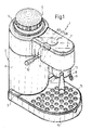
- Number 1 in Fig.s 1 and 2 indicates a coffee machine comprising an outer casing 2 consisting of a hollow base 3, a substantially cylindrical upright 4 extending upwards from the rear end of base 3 and closed off at the top by a wall 5 with a cap 6 on top, and an appendix 7 substantially in the form of a rectangular parallelepipedon and projecting radially outwards from one end of upright 4.
- a filter cup 13 designed for normally containing enough coffee powder for making two cups of coffee.
- Filter cup 13 is provided at the bottom with two spouts 14 (only one of which is visible in Fig.1) for feeding coffee into one or two cups (not shown) placed on top of a removable perforated wall 15 covering a compartment (not shown) formed inside a portion 16 of base 3 projecting forwards from the base of upright 4.
- upright 4 houses a boiler 17 consisting of a cup-shaped lower body 18 and a cup-shaped upper body 19 connected with their concave sides facing each other.
- a lower wall on body 18 presents an outer groove (not shown) housing an electric resistor 20 for heating boiler 17.
- cap 6 comprises a first cup-shaped outer body 24 having its concave side facing downwards, and a second cup-shaped inner body 25 having its concave side facing downwards and housed inside body 24 with both axial and radial slack, in such a manner that, between the inner surface of body 24 and the outer surface of both cylindrical side wall 26 and end wall 27 of body 25, there is formed a continuous gap 28 communicating externally at the bottom.
- Gap 28 is also cup-shaped with its concave side facing downwards, and is only interrupted by a number of radial bridge elements 29 connecting body 25 to body 24.
- seal 30 On the inner surface of end wall 27, there is placed a seal 30 with which cooperates, in fluidtight manner, the free end of fill pipe 22 when the outer thread 23 of the same engages an inner thread 31 on the side wall 26 of cup-shaped body 25.
- Wall 27 is provided with a hollow inner appendix 32 having a through axial hole 33 enabling boiler 17 to communiacte with gap 28 and controlled by a safety ball valve 34 designed to enable the steam inside boiler 17 to be blown off into gap 28 and, consequently, externally, when the pressure inside boiler 17 exceeds a given value, usually 2.5 atm.
- Appendix 7 houses a distributor indicated as a whole by 35 and connected to the outer surface of upper body 19 of boiler 17.
- distributor 35 comprises a distribution chamber or tank 36, to which is connected a cup-shaped filter cup holder 37 having its concave side facing downwards and supporting filter cup 13.
- the bottom surface of chamber 36 presents a first inlet 38 communicating with the bottom end of lower body 18 of boiler 17 via an outer pipe 39 (Fig.2) and via a ball valve 40 located on pipe 39 and designed to allow water to flow from boiler 17 to chamber 36 only when the pressure inside boiler 17 exceeds a given value, usually 1.5 atm.
- the bottom surface of chamber 36 also presents a second inlet 41 communicating with boiler 17 via a pipe 42 which comes out inside the top end of boiler 17; a first outlet 43 communicating with filter cup holder 37 via a water outlet pipe 44; a second outlet 45 communicating with nozzle 9 via steam outlet pipe 8; and a third exhaust outlet 46 communicating externally via an exhaust pipe 47 (Fig.2) the free end of which comes out inside the compartment (not shown) closed off by perforated wall 15.
- Chamber 36 is defined, at the bottom, by a circular bottom wall and, laterally, by a cylindrical wall 48.
- the said second inlet 41 is formed centrally through the said bottom wall, whereas the said first inlet 38 and outlets 43, 45 and 46 are formed through the said bottom wall and unevenly spaced about the same circumference coaxial with the said second inlet 41.
- chamber 36 is closed off at the top by a lid 49 secured to wall 48 by means of screws 50, and houses a switch device indicated as a whole by 51 and comprising a clearance disc 52 resting in fluid tight manner on the upper surface of the bottom wall of chamber 36.
- Disc 52 presents a number of holes 53 arranged matching inlets 38 and 41 and outlets 43, 44 and 45, and is secured angularly in relation to chamber 36 by means of a boss 54 engaged inside a recess 55 formed on the bottom wall of chamber 36.
- Switch device 51 also comprises a switch disc 56 placed on top of clearance disc 52 and designed to turn about its own axis in contact with the upper surface of clearance disc 52.
- On to the upper surface of switch disc 56 there is fitted a control plate 57 held contacting switch disc 56 by means of a spring 58 pressed between plate 57 and lid 49 with a washer 59 in between.
- From the upper surface of plate 57 there extends upwards a pin 60 which comes out of chamber 36 through a hole 61 formed centrally in lid 49, and which presents, on its free end, a square head 62 fitted with a gear wheel 63 connected to sector gear 11.
- the lower surface of switch disc 56 presents a first radial groove 64 designed to connect second inlet 41 to second outlet 45 for a given angular position of switch disc 56; and a second curved groove 65 for selectively connecting first outlet 43 to first inlet 38 and to third outlet 46, or for disconnecting first inlet 38 when the said first groove 64 connects the said second inlet 41 to the said second outlet 45.
- gear wheel 63 cooperates with an element 66 controlling a microswitch 67, and presents a lateral faced portion 68 which, cooperating with control element 66 with gear wheel 63 in a given angular position in relation to chamber 36, causes the said microswitch 67 to open.
- Microswitch 67 forms part of an electric control circuit 69 illustrated in Fig.9 and comprising a mains socket 70; an on/off switch 71; a parallel-connected "on" indicator light 72 controlled solely by switch 71; a thermostat 73 series-connected to switch 71 and to resistor 20 for disconnecting the said resistor 20 should the temperature inside boiler 17 exceed a given maximum value, usually 120-130°C; and a temperature fuse 74 set so as to trip in the event of the temperature inside boiler 17 exceeding a critical temperature, usually 210-220°C.
- filter cup holder 37 presents an annular, downward-facing appendix 75 designed to receive the top end of filter cup 13 and having slots 76 enabling filter cup 13 to be bayonet-connected to filter cup holder 37.
- socket 70 is connected to the mains; filter cup 13 is removed from filter cup holder 37; filter cup 13 is filled with enough coffee powder for making two cups; boiler 17 is filled with water through fill pipe 22; cap 6 is screwed on; and distributor 35 is switched from the first stop or exhaust position shown in Fig.6 to the coffee-making position shown in Fig.7.
- Machine 1 is now ready to operate, and may be turned on by turning on switch 71 so as to supply current to cir cuit 69.
- valve-opening pressure corresponds to a water temperature of over 100°C inside the boiler, water starts to flow through chamber 36 into filter cup 13 and, via spouts 14, into the coffee cups.
- control element 66 moves into contact with faced portion 68 so as to open microswitch 67 and de-activate resistor 20.
- groove 65 is moved so as to enable communication between water outlet 43 and exhaust outlet 46 and so blow off externally the remaining pressure inside filter cup 13.
- the possibility of setting distributor 35, at any time, to the stop position shown in Fig.6 provides for considerable advantages in that, in addition to enabling the user to regulate, as required, the amount of water fed through the coffee powder inside filter cup 13, and, consequently, also the quality and strength of the coffee produced, it also provides for safely removing filter cup 13 and refilling the same with fresh coffee powder for producing another two cups. This is made possible in that the volume of water inside boiler 17 is usually greater than that required for making four normal-size cups.
- the volume of water inside boiler 17 is also sufficient for producing dry steam at any time, in particular, after producing four cups of coffee, by switching lever 10 so as to set distributor 35 to the operating position shown in Fig.8.
- valve 34 opens so as to enable the steam to be blown off into gap 28, and out downwards, with no danger whatsoever to the user.
- Machine 1 therefore enables the user not only to control, as required, the quality and strength of the coffee produced, but also to produce fresh coffee and/or steam at any time; unlike known coffee machines of the same type, whereby all the water inside the boiler is fed through the coffee powder in one go with no possibility of control, thus supplying the user with no more than standard, and more often than not, heated coffee.
- Filter cup 13 may obviously be fitted with a known type of volume limiting device (not shown) enabling the use of sufficient coffee powder for one cup, which, in this case, is placed beneath both spouts 14.
- distributor 77 comprises a distribution chamber or tank 36 to which is connected filter cup holder 37.
- the bottom surface of chamber 36 presents an inlet 38 communicating with outer pipe 39 (Fig.2), a first outlet 43 communicating with filter cup holder 37 via water outlet pipe 44, and a second exhaust outlet 46 communicating externally via exhaust pipe 47 (Fig.2).
- Inlet 38 and outlets 43 and 46 are arranged successively about a circumference coaxial with wall 48.
- chamber 36 which is closed off at the top by lid 49 secured by means of screws 50, houses a switch device indicated as a whole by 78 and comprising a switch disc 79 designed to turn about its own axis and contacting the upper surface of the bottom wall of chamber 36.
- switch disc 79 On the upper surface of switch disc 79, there are formed two diametrically-opposed holes 80, each of which is engaged by a respective pin 81 extending axially from a control plate 82 held contacting switch disc 79 by a pack of washers 83 comprising spring washers 84 pressed between plate 82 and lid 49.
- switch disc 79 As shown in Fig.s 12 to 14, the lower surface of switch disc 79 is provided with a circumferential groove 86 which, when switch disc 79 is set to a first idle position as shown in Fig.14, enables communication between outlets 43 and 46. When, on the other hand, switch disc 79 is set to the operating position shown in Fig.13, groove 86 shifts so as to enable communication between inlet 38 and outlet 43.
- distributor 77 presents a through pipe 87 which comes out outside chamber 36 and is connected, at one end, to the top end of boiler 17 and, at the other to pipe 8 via a needle valve 88.
- Valve 88 comprises a tubular body 89 having a threaded end 90 screwed inside a threaded seat 91 on an appendix 92 of distributor 77.
- Tubular body 89 presents an axial pipe (not shown) communicating with pipe 87 and engaged by a pin (not shown) designed to move axially along tubular body 89 by virtue of a rotary control shaft 93 controlled externally by means of a knob (not shown) for enabling and cutting off communication between pipe 87 and a hole 94 formed radially through body 89.
- Pipe 8 extends radially from a tubular connecting element 95 fitted in sealed manner on to tubular body 89 and secured to the same by means of nut 96.
- Element 95 presents an inner annular groove 97 facing a matching annular groove 98 formed on the outer surface of tubular body 89 and into the bottom of which the outer end of hole 94 comes out.
- machine 1 when equipped with distributor 77, is controlled by a control circuit 99 substantially identical to circuit 69, the only difference being that it has no microswitch 67.
- resistor 20 is connected and disconnected solely by thermostat 73 when switch 71 is closed.
Landscapes
- Engineering & Computer Science (AREA)
- Food Science & Technology (AREA)
- Apparatus For Making Beverages (AREA)
- Beverage Vending Machines With Cups, And Gas Or Electricity Vending Machines (AREA)
Applications Claiming Priority (4)
| Application Number | Priority Date | Filing Date | Title |
|---|---|---|---|
| IT5383585U | 1985-09-23 | ||
| IT8553835U IT206209Z2 (it) | 1985-09-23 | 1985-09-23 | Macchina da caffe |
| IT5330486U IT207790Z2 (it) | 1986-04-21 | 1986-04-21 | Macchina da caffe |
| IT5330486U | 1986-04-21 |
Publications (2)
| Publication Number | Publication Date |
|---|---|
| EP0217211A2 true EP0217211A2 (de) | 1987-04-08 |
| EP0217211A3 EP0217211A3 (de) | 1987-10-21 |
Family
ID=26329562
Family Applications (1)
| Application Number | Title | Priority Date | Filing Date |
|---|---|---|---|
| EP86112699A Withdrawn EP0217211A3 (de) | 1985-09-23 | 1986-09-15 | Kaffeemaschine |
Country Status (5)
| Country | Link |
|---|---|
| EP (1) | EP0217211A3 (de) |
| CA (1) | CA1258591A (de) |
| DE (1) | DE8625346U1 (de) |
| ES (1) | ES1001626Y (de) |
| FR (1) | FR2587607B1 (de) |
Cited By (6)
| Publication number | Priority date | Publication date | Assignee | Title |
|---|---|---|---|---|
| EP0307497A1 (de) * | 1987-09-16 | 1989-03-22 | Arthur Eugster Elektro-Haushaltgeräte | Vorrichtung für die Zubereitung von Heissgetränken |
| EP0483700A1 (de) * | 1990-11-02 | 1992-05-06 | Eldom Rothrist Ag | Vorrichtung zur Zubereitung von Heissgetränken |
| EP0516884A3 (en) * | 1991-05-31 | 1993-04-07 | Sanyo Electric Co., Ltd. | Extraction system |
| EP0561741A1 (de) * | 1992-03-19 | 1993-09-22 | COSMEC S.r.l. | Verfahren und Vorrichtung zur Zubereitung von Kaffeegetränken |
| WO1996038078A1 (fr) * | 1995-06-02 | 1996-12-05 | Seb S.A. | Vanne de commande a plusieurs voies pour machine a boisson chaude, en particulier machine a cafe, equipee d'une chaudiere basse pression |
| EP0797945A1 (de) * | 1996-03-25 | 1997-10-01 | SCHMED, Arthur | Filterkaffeemaschine |
Families Citing this family (2)
| Publication number | Priority date | Publication date | Assignee | Title |
|---|---|---|---|---|
| DE3911169C1 (de) * | 1989-04-06 | 1990-10-25 | Wmf Wuerttembergische Metallwarenfabrik Ag, 7340 Geislingen, De | |
| CN104116412B (zh) * | 2014-07-23 | 2016-08-24 | 广东新宝电器股份有限公司 | 饮料酿造装置和饮料酿造的方法 |
Family Cites Families (10)
| Publication number | Priority date | Publication date | Assignee | Title |
|---|---|---|---|---|
| DE282677C (de) * | ||||
| FR818729A (fr) * | 1937-03-05 | 1937-10-02 | Distributeur rotatif pour l'obtention du café et autres infusions dans les appareils de consommation directe | |
| FR1270180A (fr) * | 1960-10-10 | 1961-08-25 | Ma C Fa | Machine à usages domestiques pour faire du café express |
| FR1529391A (fr) * | 1966-11-10 | 1968-06-14 | Pavoni Spa | Groupe pour machines à café |
| CH474989A (de) * | 1966-11-29 | 1969-07-15 | Kispesti Elektromos Es Finomme | Kaffeemaschine, insbesondere zur Erzeugung von Mokkakaffee |
| FR2331989A1 (fr) * | 1975-11-21 | 1977-06-17 | Seb Sa | Cafetiere a pression |
| US4204465A (en) * | 1978-11-17 | 1980-05-27 | Adams Industries, Inc. | Steam and hot liquid dispensing device |
| DE3221953A1 (de) * | 1981-06-12 | 1983-01-20 | Goblin Ltd B V C | Geraet zur getraenkezubereitung |
| CH657034A5 (it) * | 1983-04-01 | 1986-08-15 | Gaggia Brevetti | Macchina per la preparazione del caffe espresso, particolarmente per uso domestico. |
| NL8400116A (nl) * | 1984-01-13 | 1985-08-01 | Philips Nv | Espresso-apparaat. |
-
1986
- 1986-09-15 EP EP86112699A patent/EP0217211A3/de not_active Withdrawn
- 1986-09-22 CA CA000518738A patent/CA1258591A/en not_active Expired
- 1986-09-23 DE DE8625346U patent/DE8625346U1/de not_active Expired
- 1986-09-23 ES ES19868600553U patent/ES1001626Y/es not_active Expired
- 1986-09-23 FR FR868613289A patent/FR2587607B1/fr not_active Expired - Lifetime
Cited By (8)
| Publication number | Priority date | Publication date | Assignee | Title |
|---|---|---|---|---|
| EP0307497A1 (de) * | 1987-09-16 | 1989-03-22 | Arthur Eugster Elektro-Haushaltgeräte | Vorrichtung für die Zubereitung von Heissgetränken |
| EP0483700A1 (de) * | 1990-11-02 | 1992-05-06 | Eldom Rothrist Ag | Vorrichtung zur Zubereitung von Heissgetränken |
| CH681685A5 (de) * | 1990-11-02 | 1993-05-14 | Eldom Rothrist Ag | |
| EP0516884A3 (en) * | 1991-05-31 | 1993-04-07 | Sanyo Electric Co., Ltd. | Extraction system |
| EP0561741A1 (de) * | 1992-03-19 | 1993-09-22 | COSMEC S.r.l. | Verfahren und Vorrichtung zur Zubereitung von Kaffeegetränken |
| WO1996038078A1 (fr) * | 1995-06-02 | 1996-12-05 | Seb S.A. | Vanne de commande a plusieurs voies pour machine a boisson chaude, en particulier machine a cafe, equipee d'une chaudiere basse pression |
| FR2734882A1 (fr) * | 1995-06-02 | 1996-12-06 | Seb Sa | Vanne de commande a plusieurs voies pour machine a boisson chaude, en particulier machine a cafe, equipee d'une chaudiere basse pression |
| EP0797945A1 (de) * | 1996-03-25 | 1997-10-01 | SCHMED, Arthur | Filterkaffeemaschine |
Also Published As
| Publication number | Publication date |
|---|---|
| EP0217211A3 (de) | 1987-10-21 |
| FR2587607A1 (fr) | 1987-03-27 |
| ES1001626U (es) | 1988-05-16 |
| FR2587607B1 (fr) | 1990-05-11 |
| ES1001626Y (es) | 1989-01-01 |
| DE8625346U1 (de) | 1987-02-26 |
| CA1258591A (en) | 1989-08-22 |
Similar Documents
| Publication | Publication Date | Title |
|---|---|---|
| US4632024A (en) | Coffee machine | |
| US5046409A (en) | Machine for brewing hot beverages | |
| CA1218858A (en) | Apparatus for domestic use to prepare hot drinks by steam jet, in particular to prepare "italian cappuccino" | |
| JPS5941772Y2 (ja) | 家族及び小喫茶室用コ−ヒ−沸し器 | |
| US6557584B1 (en) | Flow control and flow rate control mechanisms for use in brewing machines with fluidly connected chambers | |
| EP1600086B1 (de) | Elektrische Kaffeemaschine zur Herstellung von Espresso-Kaffee | |
| AU570769B2 (en) | Coffee pot | |
| US6990891B2 (en) | Seal in a coffeemaker | |
| JPH03178614A (ja) | コーヒーメーカー | |
| US5142610A (en) | Liquid heating and dispensing appliance and valve construction | |
| US4660466A (en) | Espresso coffee machine | |
| EP0607759B1 (de) | Aufschaumvorrichtung für Dampf, insbesondere bei der Bereitung von Heissgetränken | |
| US4204465A (en) | Steam and hot liquid dispensing device | |
| US20050076785A1 (en) | Brewing apparatus hot water discharge head | |
| US20090202691A1 (en) | Coffee making apparatus and method | |
| EP1658796B1 (de) | Kaffeemaschine und Verfahren zum Herstellen von warmen Getränken | |
| US4805523A (en) | Combination electric coffee maker and water heater | |
| EP0326174B1 (de) | Dampfinhalator | |
| US4843954A (en) | Tea making machine | |
| EA003654B1 (ru) | Кофеварка со встроенным устройством для подачи пара | |
| WO1998041132A1 (en) | Coffee grinder and maker | |
| EP0217211A2 (de) | Kaffeemaschine | |
| JP2011507649A (ja) | 液体加熱装置 | |
| US5992299A (en) | Coffee makers | |
| CA2482115A1 (en) | Brewing apparatus pod carrier and frothing attachment |
Legal Events
| Date | Code | Title | Description |
|---|---|---|---|
| PUAI | Public reference made under article 153(3) epc to a published international application that has entered the european phase |
Free format text: ORIGINAL CODE: 0009012 |
|
| AK | Designated contracting states |
Kind code of ref document: A2 Designated state(s): AT BE CH DE FR GB IT LI LU NL SE |
|
| PUAL | Search report despatched |
Free format text: ORIGINAL CODE: 0009013 |
|
| AK | Designated contracting states |
Kind code of ref document: A3 Designated state(s): AT BE CH DE FR GB IT LI LU NL SE |
|
| 17P | Request for examination filed |
Effective date: 19880411 |
|
| 17Q | First examination report despatched |
Effective date: 19890612 |
|
| STAA | Information on the status of an ep patent application or granted ep patent |
Free format text: STATUS: THE APPLICATION IS DEEMED TO BE WITHDRAWN |
|
| 18D | Application deemed to be withdrawn |
Effective date: 19891223 |
|
| RIN1 | Information on inventor provided before grant (corrected) |
Inventor name: CORTESE, VIRGINIO |