EP0217377A2 - Apparat zur Verbrennung von Gasen bestehend aus Wasserstoff und zur Abkühlung der sich ergebenden Verbrennungsgase - Google Patents
Apparat zur Verbrennung von Gasen bestehend aus Wasserstoff und zur Abkühlung der sich ergebenden Verbrennungsgase Download PDFInfo
- Publication number
- EP0217377A2 EP0217377A2 EP86113502A EP86113502A EP0217377A2 EP 0217377 A2 EP0217377 A2 EP 0217377A2 EP 86113502 A EP86113502 A EP 86113502A EP 86113502 A EP86113502 A EP 86113502A EP 0217377 A2 EP0217377 A2 EP 0217377A2
- Authority
- EP
- European Patent Office
- Prior art keywords
- hydrogen
- containment
- gases
- air
- heat
- Prior art date
- Legal status (The legal status is an assumption and is not a legal conclusion. Google has not performed a legal analysis and makes no representation as to the accuracy of the status listed.)
- Withdrawn
Links
Images

Classifications
-
- G—PHYSICS
- G21—NUCLEAR PHYSICS; NUCLEAR ENGINEERING
- G21C—NUCLEAR REACTORS
- G21C15/00—Cooling arrangements within the pressure vessel containing the core; Selection of specific coolants
-
- G—PHYSICS
- G21—NUCLEAR PHYSICS; NUCLEAR ENGINEERING
- G21C—NUCLEAR REACTORS
- G21C19/00—Arrangements for treating, for handling, or for facilitating the handling of, fuel or other materials which are used within the reactor, e.g. within its pressure vessel
- G21C19/28—Arrangements for introducing fluent material into the reactor core; Arrangements for removing fluent material from the reactor core
- G21C19/30—Arrangements for introducing fluent material into the reactor core; Arrangements for removing fluent material from the reactor core with continuous purification of circulating fluent material, e.g. by extraction of fission products deterioration or corrosion products, impurities, e.g. by cold traps
- G21C19/317—Recombination devices for radiolytic dissociation products
-
- Y—GENERAL TAGGING OF NEW TECHNOLOGICAL DEVELOPMENTS; GENERAL TAGGING OF CROSS-SECTIONAL TECHNOLOGIES SPANNING OVER SEVERAL SECTIONS OF THE IPC; TECHNICAL SUBJECTS COVERED BY FORMER USPC CROSS-REFERENCE ART COLLECTIONS [XRACs] AND DIGESTS
- Y02—TECHNOLOGIES OR APPLICATIONS FOR MITIGATION OR ADAPTATION AGAINST CLIMATE CHANGE
- Y02E—REDUCTION OF GREENHOUSE GAS [GHG] EMISSIONS, RELATED TO ENERGY GENERATION, TRANSMISSION OR DISTRIBUTION
- Y02E30/00—Energy generation of nuclear origin
- Y02E30/30—Nuclear fission reactors
Definitions
- This invention relates to a process, and apparatus therefor, wherein a gaseous mixture from a nuclear reactor containing hydrogen and air is heated to its ignition temperature in a hydrogen recombiner, the resulting gaseous combustion product, which is substantially above the said ignition temperature, is cooled below said ignition temperature, and the cooled gaseous product is then discharged from said hydrogen recombiner.
- the present invention resides in a hydrogen recombining apparatus including a housing containing electric heaters therein for heating air from the containment of a nuclear power plant which air includes hydrogen, said heaters being disposed in a channel in which the hydrogen-containing air is conducted past the heaters and heated to convert the hydrogen by oxidation to water vapor, the temperature of the resultant gaseous mixture thereby rising to a level in excess of the ignition temperature of the hydrogen, characterized in that a cooling means is arranged in said housing above said electric heaters for cooling the resulting gaseous mixture after said heating to a temperature below said ignition temperature before the discharge of the gaseous mixture from the hydrogen recombiner and that means are provided for supplying at least some of the hear removed from said exhaust gas mixture to the air taken from the containment for heating the air before it is conducted past said heaters.
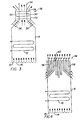
- a hydrogen recombiner 2 as known in the art, that comprises an outer housing 4 and an inner housing 6 fixedly mounted, by means not shown, above the floor 8 of outer housing 4.
- inner housing 6 mounted within inner housing 6, by means not shown, are electric heaters 10.
- the base 12 of inner housing 6 is provided with spaced, dispersed orifices 14.
- Wall 16 of outer housing 4, as well as the remaining parallel wall thereof that cannot be seen in Figure 1, are provided with louvers 18 through which containment gases enter hydrogen recombiner 2 to be burned therein.
- the remaining wall 20 of outer housing 4, as well as the remaining parallel wall thereof that cannot be seen in Figure 1, are provided with lower louvers 22 and upper louvers 24 that communicate with similar closed chambers 26 that are sealed off from the remainder of the hydrogen recombiner but which are adjacent to electric heaters 10.
- the upper end of hydrogen recombiner is provided in wall 28 thereof, as well as in the remaining walls that cannot be seen in Figure 1 with louvers 30.
- Disposed above electric heaters 10 is a baffle plate 32 and a distribution plate 34.
- the electric heaters 10 are always on, with power sufficient to raise the temperature of a gaseous mixture containing hydrogen and oxygen to its ignition temperature.
- gases are drawn continuously through outer housing 4 through louvers 18, and then upwardly through orifices 14 into contact with electric heaters 10.
- the heated gases move upwardly and are funneled by baffle plate 32 into contact with distribution plate 34, which then uniformly directs the heated gas to louvers 30 for discharge from the hydrogen recombiner.
- the novel apparatus herein is similar to that described above, except that in place of the upper end of the hydrogen recombiner 2, there is provided a heat-exchange unit for cooling the gases, after they have been heated to their ignition temperature by electric heaters 10 and reaction resulting in the conversion of hydrogen to water vapor has taken place, with the temperature of the resultant gaseous mixture thereby being raised to a temperature above said ignition temperature, being cooled to a temperature below said ignition temperature prior to discharge.
- the heat-exchange unit used is not critical as long as it is sufficient to cool the recombined gaseous mixture to a temperature below their ignition temperature prior to their discharge from the hydrogen recombiner.
- a heat exchanger 36 provided with continuous tubing or coils 38 communicating with inlet pipe 40 and exit pipe 42 carrying any suitable heat exchange medium, such as water. Cool water enters heat exchanger 36 by line 40, cooling the recombined gaseous mixture as it passes therethrough and outwardly through exits 37 of the hydrogen recombiner 2 to a temperature below its-ignition temperature.
- the water that has been heated as a result thereof is withdrawn from heat exchanger 36 by line 42, and cooled by any suitable means, for example, by passage through a water cooler 44 wherein heat is removed therefrom by using fan means 46 to blow cool air thereover.
- the cooled liquid then passes through pump 48 to continue the cooling cycle.
- the hydrogen recombiner 2 is provided with passageways 50, formed bv encircling spaced walls 52, surrounding an exit passage 5 4. Disposed in passageways 50 and extending into the upper portion of hydrogen recombiner 2 and into exit passage 50 are sealed heat pipes 56 containing a porous, flowable material that can absorb heat and can also release-said absorbed heat. Passageways 50 communicate at the lower end thereof with the atmosphere external of hydrogen recombiner 2. As a result of convection, gaseous mixtures surrounding the hydrogen recombiner 2 will move upwardly through passageways 50, picking up heat transferred through the walls of the hydrogen recombiner. Additional heat is transferred to the gaseous mixture by heat convection through pipes 56. Thus, when the gaseous mixture is discharged from passageways 50, it has absorbed an appreciable amount of heat from the recombined gases, thereby cooling the same below their ignition temperature.
- FIG. 4 The embodiment of Figure 4 is somewhat similar to Figure 3, except that heat pipes are not used but a larger number of tubes 58 are employed extending externally of hydrogen recombiner 2 into the exit passage of hydrogen recombiner and upwardly and outwardly through the exit 60 thereof. Tubes 58 communicate at each end thereof with the atmosphere external of hydrogen recombiner 2. Here, too, heat from the recombined gases is transferred to the gases passing upwardly through tubes 58, resulting in cooling the recombined gases below their ignition temperature.
- the hydrogen recombiner described herein is always in operation as long as the nuclear power plant is in operation, and containment gases are continuously passed therethrough.
- the containment gas is atmospheric air and will contain from about 100 to about 2000 parts per million by weight of hydrogen.
- the hydrogen recombiner can easily convert substantially all of the hydrogen therein by reaction with oxygen in the containment gases to form water, and cool the same below the ignition temperature.
- the containment gases being treated normally contain from about 100 to 200 parts per million of hydrogen, which in the event of a build up, can rise to about 8 to 10 volume percent.
- the containment gases will be at a temperature of about ambient temperature to about 80°C, generally about ambient temperature to about 55°C, and a pressure of about ambient pressure to about 10 kg/cm .
- containment gases are continuously drawn by convection into hydrogen recombiner 2 by way of louvers 18, through orifices 14 and then upwardly through electric heaters 10 where they are heated to their ignition temperature.
- the rate of flow of containment gases through the electric heaters 10 will vary over a wide range, but, in general, will be in the range of about 1.4 to about 4.2 cubic meter per minute.
- their temperature is raised to their ignition temperature, which can be in the range of about 570° to about 590°C, but usually about 575° to about 580°C.
- Reaction of hydrogen in the containment gases with the oxygen will then occur to form water vapor, with the result that the temperature of the resulting, or recombined gases, where 8 to 10 volume percent hydrogen is present in the containment gases could be raised to a temperature level in excess of said ignition temperature, for example, a tem- p erature of about 610 0 C to 640°C.
- the recombined gases are cooled by any suitable means, but preferably by one of the means described herein, more particularly using the embodiment exemplified in Figure 2, wherein the recombined gases are contacted in a heat exchanger through which a cooling liquid is passed, wherein they are cooled to a temperature below about 570°C, generally between about 480° to about 540°C, below said ignition temperature. Since the cooled recombined gases are now below their ignition temperature, they can be safely discharged from the hydrogen recombiner, for there will be no chance of spontaneous ignition thereof externally of the hydrogen recombiner.
Landscapes
- Physics & Mathematics (AREA)
- Engineering & Computer Science (AREA)
- Plasma & Fusion (AREA)
- General Engineering & Computer Science (AREA)
- High Energy & Nuclear Physics (AREA)
- Structure Of Emergency Protection For Nuclear Reactors (AREA)
- Organic Low-Molecular-Weight Compounds And Preparation Thereof (AREA)
Applications Claiming Priority (2)
| Application Number | Priority Date | Filing Date | Title |
|---|---|---|---|
| US782859 | 1985-10-02 | ||
| US06/782,859 US4780271A (en) | 1985-10-02 | 1985-10-02 | Process and apparatus for burning gases containing hydrogen and for cooling resulting combustion gases |
Publications (2)
| Publication Number | Publication Date |
|---|---|
| EP0217377A2 true EP0217377A2 (de) | 1987-04-08 |
| EP0217377A3 EP0217377A3 (de) | 1987-06-10 |
Family
ID=25127406
Family Applications (1)
| Application Number | Title | Priority Date | Filing Date |
|---|---|---|---|
| EP86113502A Withdrawn EP0217377A3 (de) | 1985-10-02 | 1986-10-01 | Apparat zur Verbrennung von Gasen bestehend aus Wasserstoff und zur Abkühlung der sich ergebenden Verbrennungsgase |
Country Status (5)
| Country | Link |
|---|---|
| US (1) | US4780271A (de) |
| EP (1) | EP0217377A3 (de) |
| JP (1) | JPS6287896A (de) |
| KR (1) | KR870004457A (de) |
| CN (1) | CN86106640A (de) |
Cited By (2)
| Publication number | Priority date | Publication date | Assignee | Title |
|---|---|---|---|---|
| WO1989012897A1 (fr) * | 1988-06-14 | 1989-12-28 | Johannes Wiesemes | Procede et dispositif pour evacuer un melange gazeux inflammable d'une enceinte |
| WO1994001870A1 (de) * | 1992-07-02 | 1994-01-20 | Siemens Aktiengesellschaft | Verfahren und vorrichtung zur thermischen rekombination eines gases eines gasgemisches |
Families Citing this family (11)
| Publication number | Priority date | Publication date | Assignee | Title |
|---|---|---|---|---|
| DE19503541A1 (de) * | 1995-02-03 | 1996-08-08 | Abb Management Ag | Verfahren und Vorrichtung zum Absaugen der Kondensatorabgase eines Siedewasserreaktors |
| WO1997016832A1 (en) * | 1995-10-31 | 1997-05-09 | Atomic Energy Of Canada Limited | Passive emergency hydrogen mitigation system for water-cooled nuclear reactors |
| DE19636555C1 (de) | 1996-09-09 | 1998-01-15 | Siemens Ag | Verfahren und Einrichtung zur Einleitung einer Wasserstoff-Sauerstoff-Reaktion in einem Reaktor-Sicherheitsbehälter |
| DE19704608C1 (de) * | 1997-02-07 | 1998-06-10 | Siemens Ag | Vorrichtung zur Rekombination von Wasserstoff in einem Gasgemisch |
| DE19722165C1 (de) * | 1997-05-27 | 1998-09-24 | Siemens Ag | Zündsystem zur Rekombination von Wasserstoff in einem Gasgemisch und Sicherheitsbehälter einer kerntechnischen Anlage |
| DE19852951C2 (de) * | 1998-11-17 | 2002-07-11 | Forschungszentrum Juelich Gmbh | Rekombinator zum effektiven Beseitigen von Wasserstoff aus Störfallatmosphären |
| FR2859042B1 (fr) * | 2003-08-19 | 2005-11-18 | Framatome Anp | Procede et installation de traitement de metaux alcalins charges en tritium ou de composants souilles par des metaux alcalins charges en tritium |
| KR102083508B1 (ko) * | 2012-08-06 | 2020-03-02 | 에로젯 로켓다인 오브 디이, 인크. | 냉각재 상실 사고후 완화를 위한 격납식 플레어 시스템 |
| JP2018112480A (ja) * | 2017-01-12 | 2018-07-19 | 株式会社東芝 | 水素処理装置 |
| US10839966B2 (en) | 2017-05-10 | 2020-11-17 | Westinghouse Electric Company Llc | Vortex driven passive hydrogen recombiner and igniter |
| KR102378317B1 (ko) * | 2020-09-02 | 2022-03-25 | 한국원자력연구원 | 원자로의 폭발 방지 설비 |
Family Cites Families (14)
| Publication number | Priority date | Publication date | Assignee | Title |
|---|---|---|---|---|
| DE46246C (de) * | C. C. schirm in Breslau, Museumsplatz 2 III | Apparat für optische Telegraphie | ||
| US3362883A (en) * | 1966-02-08 | 1968-01-09 | Westinghouse Electric Corp | Disposal system for contaminated hydrogen from a nuclear reactor |
| US3755075A (en) * | 1970-03-25 | 1973-08-28 | North American Rockwell | Condenser-type gas combiner |
| US4139603A (en) * | 1971-09-09 | 1979-02-13 | Westinghouse Electric Corp. | Hydrogen-oxygen recombiner |
| US3791923A (en) * | 1972-01-10 | 1974-02-12 | Universal Oil Prod Co | Recuperative thermal recombining system for handling loss of reactor coolant |
| US3937796A (en) * | 1972-01-10 | 1976-02-10 | Universal Oil Products Company | Recuperative thermal recombining system for handling loss of coolant |
| US3853482A (en) * | 1972-01-10 | 1974-12-10 | Universal Oil Prod Co | Recuperative thermal recombining system for handling loss of coolant |
| US4014984A (en) * | 1972-10-27 | 1977-03-29 | Universal Oil Products Company | Recombining of dissociated hydrogen and oxygen |
| US3859053A (en) * | 1972-10-27 | 1975-01-07 | Universal Oil Prod Co | Recombiner for dissociated hydrogen and oxygen |
| US4228132A (en) * | 1973-08-10 | 1980-10-14 | Westinghouse Electric Corp. | Hydrogen-oxygen recombiner |
| US4019871A (en) * | 1974-09-30 | 1977-04-26 | General Electric Company | Recombiner apparatus |
| US4008050A (en) * | 1975-06-11 | 1977-02-15 | Betz Erwin C | Apparatus for combining oxygen and hydrogen |
| US4091871A (en) * | 1975-07-22 | 1978-05-30 | Mildred Chiaramonte | Horseshoes made from titanium alloy compositions |
| DE3031378C2 (de) * | 1980-08-20 | 1983-04-07 | Brown Boveri Reaktor GmbH, 6800 Mannheim | Einrichtung zur Entfernung von Wasserstoffgas aus dem Sicherheitsbehälter einer Kernreaktoranlage |
-
1985
- 1985-10-02 US US06/782,859 patent/US4780271A/en not_active Expired - Fee Related
-
1986
- 1986-09-27 CN CN198686106640A patent/CN86106640A/zh active Pending
- 1986-09-29 KR KR1019860008166A patent/KR870004457A/ko not_active Withdrawn
- 1986-10-01 EP EP86113502A patent/EP0217377A3/de not_active Withdrawn
- 1986-10-02 JP JP61233409A patent/JPS6287896A/ja active Pending
Cited By (2)
| Publication number | Priority date | Publication date | Assignee | Title |
|---|---|---|---|---|
| WO1989012897A1 (fr) * | 1988-06-14 | 1989-12-28 | Johannes Wiesemes | Procede et dispositif pour evacuer un melange gazeux inflammable d'une enceinte |
| WO1994001870A1 (de) * | 1992-07-02 | 1994-01-20 | Siemens Aktiengesellschaft | Verfahren und vorrichtung zur thermischen rekombination eines gases eines gasgemisches |
Also Published As
| Publication number | Publication date |
|---|---|
| CN86106640A (zh) | 1987-05-27 |
| JPS6287896A (ja) | 1987-04-22 |
| EP0217377A3 (de) | 1987-06-10 |
| KR870004457A (ko) | 1987-05-09 |
| US4780271A (en) | 1988-10-25 |
Similar Documents
| Publication | Publication Date | Title |
|---|---|---|
| EP0217377A2 (de) | Apparat zur Verbrennung von Gasen bestehend aus Wasserstoff und zur Abkühlung der sich ergebenden Verbrennungsgase | |
| JP2701990B2 (ja) | 加圧反応炉システムとその操作方法 | |
| SE409849B (sv) | Forbrenningsanordning for att till vattenanga forbrenna i en inneslutning for en kernreaktor upptredande vetgas med syrgas | |
| US5315938A (en) | Heat accumulator | |
| KR970704252A (ko) | 연료 셀 발전소 노 | |
| US4017277A (en) | Direct contact water heating system and process | |
| US4139603A (en) | Hydrogen-oxygen recombiner | |
| KR20040104553A (ko) | 열교환기를 구비한 반응장치 | |
| US3855001A (en) | Fuel cell with air purifier | |
| GB1532757A (en) | Heat exchanger system | |
| US4926797A (en) | Wood burning hot water furnace | |
| US4232634A (en) | High efficiency hot water boiler | |
| WO1999061397A9 (en) | Water gas shift reactor and heat exchanger | |
| SE7713225L (sv) | Kompakt katalytisk reaktionsapparatur med flera ror | |
| JPS5610694A (en) | Hot-water boiler | |
| JP2004000920A (ja) | 反応装置及び反応方法 | |
| JPH0526722B2 (de) | ||
| JPS63128559A (ja) | 固体電解質燃料電池モジユ−ル | |
| SU954735A1 (ru) | Способ нагревани жидкостей | |
| RU2101079C1 (ru) | Реактор | |
| RU2264853C1 (ru) | Способ рекомбинации водорода и кислорода, находящихся в газовой смеси, рекомбинатор водорода и кислорода | |
| JPH065302A (ja) | 燃料電池発電設備の保温施工方法 | |
| JPS6471075A (en) | Reaction air supply method of fuel cell | |
| JPH02217302A (ja) | 吸熱反応のための反応室の中のプロセスガス流を間接的に加熱する方法及びこの方法を実施する装置 | |
| JPS5614401A (en) | Alcohol reforming apparatus |
Legal Events
| Date | Code | Title | Description |
|---|---|---|---|
| PUAI | Public reference made under article 153(3) epc to a published international application that has entered the european phase |
Free format text: ORIGINAL CODE: 0009012 |
|
| AK | Designated contracting states |
Kind code of ref document: A2 Designated state(s): BE DE ES FR GB IT SE |
|
| PUAL | Search report despatched |
Free format text: ORIGINAL CODE: 0009013 |
|
| AK | Designated contracting states |
Kind code of ref document: A3 Designated state(s): BE DE ES FR GB IT SE |
|
| 17P | Request for examination filed |
Effective date: 19871015 |
|
| 17Q | First examination report despatched |
Effective date: 19881021 |
|
| STAA | Information on the status of an ep patent application or granted ep patent |
Free format text: STATUS: THE APPLICATION IS DEEMED TO BE WITHDRAWN |
|
| 18D | Application deemed to be withdrawn |
Effective date: 19890503 |
|
| RIN1 | Information on inventor provided before grant (corrected) |
Inventor name: DEZUBAY, EGON ALEX Inventor name: LAIN, PHILIP JACKSON |