EP0217518A1 - Buse de pulvérisation à ultrasons et son procédé d'utilisation - Google Patents
Buse de pulvérisation à ultrasons et son procédé d'utilisation Download PDFInfo
- Publication number
- EP0217518A1 EP0217518A1 EP86306298A EP86306298A EP0217518A1 EP 0217518 A1 EP0217518 A1 EP 0217518A1 EP 86306298 A EP86306298 A EP 86306298A EP 86306298 A EP86306298 A EP 86306298A EP 0217518 A1 EP0217518 A1 EP 0217518A1
- Authority
- EP
- European Patent Office
- Prior art keywords
- atomizing surface
- nozzle
- electrical potential
- amplitude
- fluid
- Prior art date
- Legal status (The legal status is an assumption and is not a legal conclusion. Google has not performed a legal analysis and makes no representation as to the accuracy of the status listed.)
- Withdrawn
Links
- 238000000034 method Methods 0.000 title claims description 11
- 239000007921 spray Substances 0.000 title abstract description 35
- 239000012530 fluid Substances 0.000 claims abstract description 63
- 230000000737 periodic effect Effects 0.000 claims abstract description 24
- 238000000889 atomisation Methods 0.000 claims abstract description 12
- 230000004044 response Effects 0.000 claims abstract description 5
- 230000003247 decreasing effect Effects 0.000 claims abstract description 4
- 238000009827 uniform distribution Methods 0.000 claims abstract description 3
- 239000007788 liquid Substances 0.000 claims description 8
- 230000003321 amplification Effects 0.000 claims description 3
- 238000003199 nucleic acid amplification method Methods 0.000 claims description 3
- 230000006872 improvement Effects 0.000 abstract description 5
- 238000009826 distribution Methods 0.000 abstract description 3
- 230000007704 transition Effects 0.000 description 8
- 230000008901 benefit Effects 0.000 description 7
- 230000006870 function Effects 0.000 description 5
- 239000004020 conductor Substances 0.000 description 4
- 238000010276 construction Methods 0.000 description 4
- 239000000463 material Substances 0.000 description 4
- 238000013461 design Methods 0.000 description 3
- 238000011161 development Methods 0.000 description 3
- 238000010586 diagram Methods 0.000 description 3
- 230000015572 biosynthetic process Effects 0.000 description 2
- 238000004519 manufacturing process Methods 0.000 description 2
- 230000007246 mechanism Effects 0.000 description 2
- 230000004048 modification Effects 0.000 description 2
- 238000012986 modification Methods 0.000 description 2
- 238000005507 spraying Methods 0.000 description 2
- 239000000758 substrate Substances 0.000 description 2
- FYYHWMGAXLPEAU-UHFFFAOYSA-N Magnesium Chemical compound [Mg] FYYHWMGAXLPEAU-UHFFFAOYSA-N 0.000 description 1
- RTAQQCXQSZGOHL-UHFFFAOYSA-N Titanium Chemical compound [Ti] RTAQQCXQSZGOHL-UHFFFAOYSA-N 0.000 description 1
- 230000009471 action Effects 0.000 description 1
- 230000002411 adverse Effects 0.000 description 1
- XAGFODPZIPBFFR-UHFFFAOYSA-N aluminium Chemical compound [Al] XAGFODPZIPBFFR-UHFFFAOYSA-N 0.000 description 1
- 229910052782 aluminium Inorganic materials 0.000 description 1
- 230000009286 beneficial effect Effects 0.000 description 1
- 230000008602 contraction Effects 0.000 description 1
- 230000001276 controlling effect Effects 0.000 description 1
- 238000009792 diffusion process Methods 0.000 description 1
- 239000003814 drug Substances 0.000 description 1
- 230000000694 effects Effects 0.000 description 1
- 238000005304 joining Methods 0.000 description 1
- 229910052749 magnesium Inorganic materials 0.000 description 1
- 239000011777 magnesium Substances 0.000 description 1
- 238000012423 maintenance Methods 0.000 description 1
- 210000002445 nipple Anatomy 0.000 description 1
- 230000010287 polarization Effects 0.000 description 1
- 230000008569 process Effects 0.000 description 1
- 230000009467 reduction Effects 0.000 description 1
- 230000001105 regulatory effect Effects 0.000 description 1
- 238000007493 shaping process Methods 0.000 description 1
- 229910052719 titanium Inorganic materials 0.000 description 1
- 239000010936 titanium Substances 0.000 description 1
Images

Classifications
-
- B—PERFORMING OPERATIONS; TRANSPORTING
- B05—SPRAYING OR ATOMISING IN GENERAL; APPLYING FLUENT MATERIALS TO SURFACES, IN GENERAL
- B05B—SPRAYING APPARATUS; ATOMISING APPARATUS; NOZZLES
- B05B17/00—Apparatus for spraying or atomising liquids or other fluent materials, not covered by the preceding groups
- B05B17/04—Apparatus for spraying or atomising liquids or other fluent materials, not covered by the preceding groups operating with special methods
- B05B17/06—Apparatus for spraying or atomising liquids or other fluent materials, not covered by the preceding groups operating with special methods using ultrasonic or other kinds of vibrations
- B05B17/0607—Apparatus for spraying or atomising liquids or other fluent materials, not covered by the preceding groups operating with special methods using ultrasonic or other kinds of vibrations generated by electrical means, e.g. piezoelectric transducers
- B05B17/0623—Apparatus for spraying or atomising liquids or other fluent materials, not covered by the preceding groups operating with special methods using ultrasonic or other kinds of vibrations generated by electrical means, e.g. piezoelectric transducers coupled with a vibrating horn
- B05B17/063—Apparatus for spraying or atomising liquids or other fluent materials, not covered by the preceding groups operating with special methods using ultrasonic or other kinds of vibrations generated by electrical means, e.g. piezoelectric transducers coupled with a vibrating horn having an internal channel for supplying the liquid or other fluent material
-
- B—PERFORMING OPERATIONS; TRANSPORTING
- B05—SPRAYING OR ATOMISING IN GENERAL; APPLYING FLUENT MATERIALS TO SURFACES, IN GENERAL
- B05B—SPRAYING APPARATUS; ATOMISING APPARATUS; NOZZLES
- B05B17/00—Apparatus for spraying or atomising liquids or other fluent materials, not covered by the preceding groups
- B05B17/04—Apparatus for spraying or atomising liquids or other fluent materials, not covered by the preceding groups operating with special methods
- B05B17/06—Apparatus for spraying or atomising liquids or other fluent materials, not covered by the preceding groups operating with special methods using ultrasonic or other kinds of vibrations
- B05B17/0607—Apparatus for spraying or atomising liquids or other fluent materials, not covered by the preceding groups operating with special methods using ultrasonic or other kinds of vibrations generated by electrical means, e.g. piezoelectric transducers
- B05B17/0623—Apparatus for spraying or atomising liquids or other fluent materials, not covered by the preceding groups operating with special methods using ultrasonic or other kinds of vibrations generated by electrical means, e.g. piezoelectric transducers coupled with a vibrating horn
Definitions
- Ultrasonic nozzles which operate at a single drive frequency are well known and offer numerous advantages over conventional hydraulic and pneumatic spray nozzles. Typically, such ultrasonic nozzles provide reduced spray velocities, infinitely variable control of fluid spray rates and significantly reduced operating power consumption.
- ultrasonic nozzles utilize the ultrasonic mechanical vibrations of a piezoelectric transducer to vibrate an atomizing surface and thereby atomize a fluid disposed thereon.
- the absence of such pressures and gas streams results in the development of a droplet fog wherein the average velocity of individual droplets is very low compared to those produced by other atomizing techniques.
- a low average droplet velocity is of great benefit in that overspray and excess fluid delivery are both reduced, spray patterns made up of such low velocity droplets are often poorly defined. Accordingly, definite measures must be taken whenever the spray pattern shape provided by an ultrasonic nozzle is of importance.
- One well-known technique for controlling the spray pattern of an ultrasonic nozzle involved entraining the spray droplets in a moving air stream and then shaping the air stream to provide the desired spray pattern. While this technique was effective, it had the disadvantage of requiring often complex, bulky, and expensive air blowers and related equipment.
- Another well-known spray pattern control technique involved the use of a shaped atomizing surface in the construction of the ultrasonic nozzle. This technique was based on the principle that the individual droplets, produced when a uniform liquid film is atomized by an ultrasonically vibrating surface, will be thrown off in a perpendicular direction relative to the surface. Accordingly, the initial shape of the spray pattern produced by such an ultrasonic nozzle should, in theory, be related to the shape of the generating atomizing surface.
- the present invention is directed to an ultrasonic spray nozzle system and method wherein a parameter of the ultrasonic energy applied to the nozzle is varied with respect to time so as to result in a periodic increase and decrease in the vibrational amplitude of the nozzle's atomizing surface.
- a parameter of the ultrasonic energy applied to the nozzle is varied with respect to time so as to result in a periodic increase and decrease in the vibrational amplitude of the nozzle's atomizing surface.
- This permits fluid to more uniformly cover the atomizing surface during periods of low vibrational amplitude and to thereafter be atomized into a well defined spray pattern during periods of increased vibrational amplitude.
- the nozzle can be provide with one or more auxiliary fluid-flow ports which function to evenly distribute the fluid over the atomizing surface during periods of reduced vibrational amplitude.
- an ultrasonic nozzle includes a piezoelectric transducer which expands and contracts in response to an applied periodic electrical potential.
- the expansion and contraction of the piezoelectric transducer develops mechanical vibrations which appear on an atomizing surface formed on a portion of the nozzle.
- a parameter is modulated with time such that the vibrational amplitude of the atomizing surface is alternately increased and decreased.
- an ultrasonic nozzle having an atomizing surface, includes a fluid passage which opens through the atomizing surface at a first location thereon.
- One or more auxiliary passages which communicate with the main fluid passage, open through the atomizing surface at remote locations and function to communicate fluid to the atomizing surface such that the fluid is evenly distributed thereon.
- the ultrasonic nozzle has a characteristic resonant frequency and the frequency of the applied drive energy is periodically varied from below to above the resonant frequency of the nozzle.
- two or more ultrasonic nozzles are operated from a single source of drive energy.
- the drive energy frequency is modulated so as to periodically sweep through the resonant frequency of each nozzle. This assures that resonance is independently achieved in each nozzle over at least a portion of each frequency sweep cycle.
- Nozzle 10 comprises a pair of disc-shaped piezoelectric transducer elements 11 and 12 mounted between a pair of generally cylindrical nozzle body members 14 and 15.
- An electrically conductive electrode disc 16 is positioned between the piezoelectric transducer elements and includes a projecting terminal 17 to which an electrical conductor 18 can be connected.
- a threaded bolt 20 extends through suitably dimensioned apertures formed in the rear nozzle body member 15, the piezoelectric transducer elements 11 and 12, and the electrode disc 16, and engages a threaded recess formed in the front nozzle body member 14 as illustrated.
- bolt 20 When tightened, bolt 20 serves to join each of these elements to form a unitary nozzle structure.
- a cylindrical insulating sleeve 21 is disposed around a segment of the threaded portion 22 of bolt 20 in the vicinity of the piezoelectric transducer elements as shown and functions to electrically isolate the bolt from the transducer elements and the electrode disc.
- each transducer element is in contact with the electrode disc on one side and in contact with a nozzle body member on the other.
- bolt 20 also serves to electrically connect the front nozzle body member 14 with rear nozzle body member 15. Accordingly, an electrical potential, applied between the electrode terminal 17 and either of the nozzle body members, will appear across each of the piezoelectric transducer elements 11 and 12.
- the cut, orientation and polarization of the piezoelectric transducer elements is such that each element expands across its thickness when the potential applied to electrode disc 16 is of one polarity, and contracts when the potential applied to the electrode disc is of opposite polarity. Accordingly, the application of a periodic electrical potential between conductor 18 and either of the nozzle body members 14 or 15 will result in the development of longitudinal mechanical vibrations at the frequency of the periodic potential. Such vibrations propagate longitudinally along the ultrasonic nozzle.
- each of the nozzle body members 14 and 15 is formed of an electrically and acoustically conductive material such as aluminum, magnesium, or titanium, and is of generally circular cross-section.
- Each nozzle is designed for operation at a particular nominal operating frequency which, in turn, determines the wavelength of the mechanical vibrations.
- best operation is obtained when the length of the rear nozzle body member 15 is made equal to 1 ⁇ 4 wavelength at the nominal operating frequency while the overall length of the front nozzle body member 14 is made equal to 3 ⁇ 4 wavelength.
- the diameter of each nozzle body member is less than 1 ⁇ 4 wavelength at the nominal operating frequency.
- the diameter of the forward 1 ⁇ 4 wavelength portion of the front nozzle body member 14 is reduced to form an amplifying transition 22 and a reduced diameter nozzle stem 23 as illustrated.
- the reduction in diameter at the amplifying transition provides significant mechanical amplification of the longitudinal vibrations produced by the piezoelectric transducer elements.
- the amplification factor is equal to the ratio of cross-sectional areas of the front nozzle body member 14 and the nozzle stem 23 and in practice typically ranges between 2 and 10.
- the front nozzle body member 14 includes a threaded fluid fitting 24 which is received in a threaded recess 25 formed in its upper surface.
- Fluid fitting 24 includes an upwardly projecting nipple 26 which permits connection to a flexible fluid conduit 27 in known manner.
- a main fluid passage 28 is bored along the longitudinal axis of the nozzle stem 23 and communicates with fluid fitting 24 through a short passage 30 bored through the bottom of recess 25. Opposite the short passage 30, the main fluid flow passage 28 opens through the nozzle stem 23 at the distal end 31 thereof. Passage 28 thereby forms an opening 32 through which fluid from fluid conduit 27 can be discharged.
- the nozzle stem 23 Adjacent end 31, the nozzle stem 23 includes a frusto-conical atomizing surface 34 which tapers such that it is narrowest adjacent end 31 of the nozzle stem.
- a plurality of auxiliary fluid-flow passages 35, 36, 37, 38, 39 and 40 are formed in the nozzle stem 23 adjacent end 31 thereof and open through the atomizing surface 34 at equally spaced points thereon which are remote from the main fluid passage opening 32.
- Each auxiliary passage communicates with the main fluid passage 28 and extends in a generally radial direction therefrom.
- each auxiliary passage is also oriented perpendicularly to the atomizing surface 34 as shown, and is of smaller diameter than the main fluid passage 28.
- a periodic electrical drive signal is applied to the ultrasonic nozzle 10 through conductor 18 and the nozzle body members 14 and 15 resulting in the development of longitudinal mechanical vibrations.
- the frequency of the drive signal is substantially equal to the nominal operating frequency of the nozzle, the amplitude of these vibrations is amplified and is maximum along the atomizing surface 34.
- fluid supplied to ultrasonic nozzle 10 through fluid conduit 27 flows outwardly through main fluid passage 28 and auxiliary passages 35-40 so as to form a fluid film on the atomizing surface 34.
- this film is rapidly transformed into a multitude of small droplets which form a fog adjacent the nozzle stem end 31.
- the drive energy applied to the ultrasonic nozzle 10 is not uniform but rather is modulated such that the vibrational amplitude of the atomizing surface 34 is periodically reduced and increased with respect to time. This is achieved through modulation of at least one parameter of the periodic drive signal applied to the nozzle.
- the resulting periodic increase and decrease in the vibrational amplitude appearing on the atomizing surface results in improved spray pattern definition and freedom from clogging.
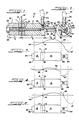
- Figure 3 depicts the vibrational standing wave pattern which results when the ultrasonic nozzle is operated at its actual resonant frequency. Since the piezoelectric transducer elements expand or contract equally on either side of the electrode disc 16, the vibrational amplitude will at all times be at a minimum at the plane defined by the electrode. Thus, a node, or vibrational minimum 41, appears at the plane of the electrode disc. Since the rear-most surface 42 of the rear nozzle body member 15 is spaced 1 ⁇ 4 wavelength from the electrode disc, an antinode, or vibrational maximum 44, appears at the rear of the nozzle. The distance between the electrode disc 16 and the amplifying transition 22 is equal to 1 ⁇ 2 wavelength and accordingly, another node 45 appears at the transition.
- the distal end 31 of the nozzle stem 23 is spaced 1 ⁇ 4 wavelength beyond the transition and, accordingly, a vibrational maximum 47 appears on the atomizing surface 34.
- the reduced diameter of the nozzle stem 23 causes the vibrational maximum 47 to be increased by the appropriate gain factor. Since a vibrational maximum is located on the atomizing surface, maximum atomization occurs when the nozzle is operated at its natural resonant frequency.
- Figure 4 illustrates the standing wave pattern which results when the nozzle is operated at a frequency greater than its natural resonant frequency.
- node 41 will remain located in the plane of the electrode disc 16.
- the relative length of the rear nozzle body member 15 is now greater than 1 ⁇ 4 wavelength. Accordingly, antinode 44 will no longer be located at the rear surface 42 of the nozzle but, rather, will be displaced toward the electrode disc as shown.
- node 45 will be displaced from transition 22 toward electrode disc 16.
- Antinode 47 will also be displaced toward the electrode disc as shown with the result that the vibrational amplitude appearing on the atomizing surface 34 is significantly reduced.
- Figure 5 illustrates the standing wave pattern which results when the ultrasonic nozzle is operated at a frequency lower than its actual resonant frequency.
- node 41 is located in the plane of the electrode disc 16.
- antinode 44 is displaced beyond the rear surface 42 of the nozzle in a direction away from the electrode disc.
- node 45 is displaced beyond transition 22 in a direction away from electrode disc 16. This has the effect of displacing the vibrational maximum 47 beyond the end 31 of the atomizing surface 34 with the result that the vibrational amplitude of the atomizing surface is significantly reduced.
- any shift of the drive signal frequency from the actual resonant frequency of the nozzle will result in a decrease in the amplitude of vibrations appearing on the atomizing surface. Accordingly, periodic modulation of the drive signal about the nozzle resonant frequency will result in a periodic increase and decrease in the vibrational amplitude as antinode 47 periodically traverses the atomizing surface.
- Figure 6 depicts the spray pattern which results when an ultrasonic nozzle 48, otherwise identical to nozzle 10, is operated at a single constant drive frequency and is not provided with the auxiliary passages 35-40.
- the spray pattern 50 of such a nozzle lacks clear definition, particularly along its side margins 51 and 52, and includes randomly located areas 54 and 55 of reduced and increased droplet concentrations respectively.
- Figure 7 illustrates the spray pattern which results when an ultrasonic nozzle 10, otherwise identical with nozzle 48 illustrated in Figure 6, is provided with auxiliary passages 35-40 and is operated such that the vibrational amplitude on the atomizing surface is periodically increased and reduced.
- the resulting spray pattern 56 is much more clearly defined than is pattern 50, particularly so along the side margins 57 and 58 which, in the embodiment illustrated, clearly define a conical form.
- pattern 56 includes distinct areas 60 and 61 of reduced and increased droplet concentration which are uniformly developed along spherically expanding wavefronts at regularly spaced intervals as shown. Although droplet concentrations differ in areas 59 and 60, the concentrations remain constant across the area of each wavefront. Accordingly, sprayed material is uniformly deposited by spray pattern 56.
- the areas of increased droplet concentration are formed during periods of maximum vibrational amplitude on the atomizing surface, and the areas of reduced droplet concentration are formed during periods of reduced vibrational amplitude. Accordingly, the spacing between the areas of reduced and increased droplet concentration is determined by the rate at which the vibrational amplitude of the atomizing surface is increased and reduced. When such variation of the vibrational amplitude is achieved through frequency modulation of the applied drive signal, the spacing of the reduced and increased droplet concentration areas is influenced by the maximum frequency deviation of the applied drive signal as well as the deviation rate.
- a frusto-conical atomizing surface should, for example, produce a generally cone-shaped spray pattern.
- the reason for this discrepancy is that fluid is not uniformly distributed over the atomizing surface when a single outlet port is utilized in conjunction with a constant vibrational amplitude. In such a case, the fluid film tends to be thicker adjacent the single outlet port than at locations spaced therefrom and accordingly, the resulting pattern deviates from that expected when a uniform film thickness is maintained.
- the improvement in spray pattern definition provided by the present invention results from the maintenance of a substantially uniform fluid film on the atomizing surface during fluid atomization.
- the rate of fluid atomization is considerably reduced and, therefore, fluid discharged from the fluid discharge opening 32 has an opportunity to become evenly distributed over the atomizing surface in a substantially uniform film.
- the uniform film is substantially atomized and, by virtue of its uniformity, more closely approximates the theoretical atomization model, with the further result that the atomization droplets more closely follow the predicted perpendicular flight path. This in turn improves the spray pattern definition.
- auxiliary fluid-flow passages also contributes to the uniform distribution of fluid onto the atomizing surface during periods of reduced vibrational amplitude and thus also contributes to improved spray pattern definition. Both modulation of the nozzle drive signal and the provision of auxiliary fluid passages each contribute to an improvement in the spray pattern definition and uniformity, though either alone will independently provide some improvement.
- a further advantage of the auxiliary fluid-flow passages is that, in contrast to prior nozzles, fluid cavitation within the fluid-flow passage 28 is not a problem to be avoided, but, rather, is of benefit in that it tends to promote fluid flow through the auxiliary passages and thereby improve the distribution of fluid over the atomizing surface. Accordingly, the need for decoupling sleeves within the fluid-flow passage 28 is eliminated.
- a further advantage of modulating the drive energy is that the formation of large droplets on the atomizing surface, which may tend to clog the nozzle, is avoided since local cavitation on the atomizing surface is reduced, if not eliminated, during periods of reduced vibrational amplitude.
- FIG 8 is a simplified functional block diagram of an electrical drive signal supply circuit suitable for use with the ultrasonic nozzle described herein.
- the drive circuit includes an oscillator 62 which develops a periodic electrical voltage in the ultrasonic frequency range (20kHz to 100kHz).
- the output of oscillator 62 is applied to an input of a modulator circuit 64 of known construction which, in the embodiment illustrated, modulates the frequency of the applied ultrasonic voltage.
- a modulation waveform signal generator 65 develops a modulating signal which, when applied to modulator 64 to modulates the ultrasonic oscillator voltage in accordance therewith.
- the modulated output of modulator 64 is applied through a voltage controlled gate 66 to the input of a class-B power amplifier 67.
- Gate 64 responds to an applied control signal and functions to selectively enable or disable the nozzle.
- the output of power amplifier 67 is coupled through a transformer 68 to the piezoelectric element 70 of an ultrasonic nozzle in order to achieve the required operating voltages (approximately 400 volts).
- a regulated DC power supply 71 is provided for energizing the ultrasonic drive generator circuitry.
- a variable resistance 72 is connected between the supply voltage and oscillator 62 to permit user adjustment of the oscillator frequency.
- the modulation waveform signal generator 65 functions to generate the signal with which the oscillator voltage is modulated and therefore determines the frequency excursions of the frequency modulated drive signal applied to ultrasonic nozzle.
- the waveform produced by generator 65 can be selected in accordance with the desired characteristics of the ultrasonic nozzle and can, for, example comprise a triangular, sawtooth or sinusoidal waveform. Typically, satisfactory operation is achieved with modulating signal frequencies between 20Hz and 5000Hz, with a maximum frequency deviation of between 200Hz and 400Hz. While these frequencies have been found to be satisfactory in actual practice, they are not to be considered limiting and satisfactory operation can be obtained at frequencies other than those specified.
- a further advantage which results when the drive signal to an ultrasonic nozzle is frequency modulated is that two or more imperfectly matched ultrasonic nozzles 74 and 75 can be operated from a single, frequency-modulated drive signal generator 76 as illustrated in Figure 9. Even though the natural resonant frequency of nozzles 74 and 75 may differ by several hundred Hz, satisfactory operation can be obtained provided the maximum frequency deviation is sufficient to assure that the drive signal frequency equals each of the nozzle resonant frequencies at some point during its excursions. Such deviation can be readily achieved, and the need for a dedicated drive signal generator in association with each nozzle, or, in the alternative, careful matching between nozzles, is not required for satisfactory operation of each nozzle. Accordingly, a substantial saving in the cost of a multi-nozzle system can be realized.
- auxiliary fluid-flow ports are not critical provided they are arranged so as to promote the formation of uniform fluid film on the atomizing surface. In some embodiments, it may be advantageous to omit the auxiliary ports altogether. It is also noted that while a frusto-conical atomizing surface has been shown and described, the invention is readily adaptable to nozzles having other atomizing surface shapes and configurations. Finally, while specific modulating waveforms, frequencies and frequency deviations have been described, satisfactory operation can be obtained using values other than those specified.
Landscapes
- Special Spraying Apparatus (AREA)
Applications Claiming Priority (2)
| Application Number | Priority Date | Filing Date | Title |
|---|---|---|---|
| US06/772,753 US4659014A (en) | 1985-09-05 | 1985-09-05 | Ultrasonic spray nozzle and method |
| US772753 | 1991-10-07 |
Publications (1)
| Publication Number | Publication Date |
|---|---|
| EP0217518A1 true EP0217518A1 (fr) | 1987-04-08 |
Family
ID=25096111
Family Applications (1)
| Application Number | Title | Priority Date | Filing Date |
|---|---|---|---|
| EP86306298A Withdrawn EP0217518A1 (fr) | 1985-09-05 | 1986-08-14 | Buse de pulvérisation à ultrasons et son procédé d'utilisation |
Country Status (3)
| Country | Link |
|---|---|
| US (1) | US4659014A (fr) |
| EP (1) | EP0217518A1 (fr) |
| CA (1) | CA1247945A (fr) |
Cited By (8)
| Publication number | Priority date | Publication date | Assignee | Title |
|---|---|---|---|---|
| DE3732325A1 (de) * | 1987-09-25 | 1989-04-13 | Battelle Institut E V | Vorrichtung zum zerstaeuben eines fluessigen mediums mit hilfe von ultraschall |
| US5164198A (en) * | 1987-09-22 | 1992-11-17 | Branson Ultaschall Niederlassung Der Emerson Technologies Gmbh & Co. | Apparatus for pulverizing at least one jet of molten metal |
| GB2291605A (en) * | 1991-11-12 | 1996-01-31 | Medix Ltd | A nebuliser and nebuliser control system |
| CN1046869C (zh) * | 1992-11-30 | 1999-12-01 | 中国科学院上海硅酸盐研究所 | 多功能大流量超声喷雾装置 |
| EP1845252A2 (fr) | 2006-04-12 | 2007-10-17 | Delavan Inc. | Injection de carburant et systèmes de mélange dotés d'éléments piézoélectrique et leurs procédés d'utilisation |
| CN102500502A (zh) * | 2011-10-10 | 2012-06-20 | 苏州科技学院 | 一种二级超声振动雾化器 |
| RU2465965C1 (ru) * | 2011-10-06 | 2012-11-10 | Общество с ограниченной ответственностью "Центр ультразвуковых технологий АлтГТУ" | Способ управления процессом ультразвукового распыления |
| WO2017046607A1 (fr) * | 2015-09-17 | 2017-03-23 | The James Hutton Institute | Ensemble atomiseur |
Families Citing this family (111)
| Publication number | Priority date | Publication date | Assignee | Title |
|---|---|---|---|---|
| US4806455A (en) * | 1987-04-03 | 1989-02-21 | Macdermid, Incorporated | Thermal stabilization of photoresist images |
| US5039614A (en) * | 1988-06-16 | 1991-08-13 | Armenag Dekmezian | Method and apparatus for collecting samples for analysis of chemical composition |
| CA1319539C (fr) * | 1988-06-16 | 1993-06-29 | Armenag H. Dekmezian | Methode et appareillage pour la cueillette d'echantillons utilises pour l'analyse de compositions chimiques |
| EP0458638B1 (fr) * | 1990-05-24 | 1997-04-09 | Canon Kabushiki Kaisha | Moteur à ondes de vibrations |
| EP0480615B1 (fr) * | 1990-10-11 | 1996-02-14 | Kohji Toda | Pulvérisateur à ultrasons |
| FR2669561B1 (fr) * | 1990-11-22 | 1995-03-03 | Dominique Dubruque | Dispositif de pulverisation ultrasonique de fluide. |
| US6540154B1 (en) * | 1991-04-24 | 2003-04-01 | Aerogen, Inc. | Systems and methods for controlling fluid feed to an aerosol generator |
| US6629646B1 (en) * | 1991-04-24 | 2003-10-07 | Aerogen, Inc. | Droplet ejector with oscillating tapered aperture |
| US5938117A (en) | 1991-04-24 | 1999-08-17 | Aerogen, Inc. | Methods and apparatus for dispensing liquids as an atomized spray |
| US7628339B2 (en) | 1991-04-24 | 2009-12-08 | Novartis Pharma Ag | Systems and methods for controlling fluid feed to an aerosol generator |
| US5219120A (en) * | 1991-07-24 | 1993-06-15 | Sono-Tek Corporation | Apparatus and method for applying a stream of atomized fluid |
| US5145113A (en) * | 1991-08-30 | 1992-09-08 | United Technologies Corporation | Ultrasonic generation of a submicron aerosol mist |
| US5152457A (en) * | 1991-08-30 | 1992-10-06 | United Technologies Corporation | Ultrasonic mist generator with multiple piezoelectric crystals |
| US5387444A (en) * | 1992-02-27 | 1995-02-07 | Dymax Corporation | Ultrasonic method for coating workpieces, preferably using two-part compositions |
| US5529753A (en) * | 1993-07-09 | 1996-06-25 | Dade International Inc. | System for ultrasonic energy coupling by irrigation |
| US6014970A (en) * | 1998-06-11 | 2000-01-18 | Aerogen, Inc. | Methods and apparatus for storing chemical compounds in a portable inhaler |
| US5758637A (en) | 1995-08-31 | 1998-06-02 | Aerogen, Inc. | Liquid dispensing apparatus and methods |
| US6085740A (en) | 1996-02-21 | 2000-07-11 | Aerogen, Inc. | Liquid dispensing apparatus and methods |
| US6205999B1 (en) | 1995-04-05 | 2001-03-27 | Aerogen, Inc. | Methods and apparatus for storing chemical compounds in a portable inhaler |
| US6782886B2 (en) | 1995-04-05 | 2004-08-31 | Aerogen, Inc. | Metering pumps for an aerosolizer |
| DE1005917T1 (de) * | 1998-12-01 | 2001-01-11 | Microflow Engineering S.A., Neuenburg/Neuchatel | Inhalator mit Ultraschallzerstäuber dessen Sprühöffnungen den Maximalamplituden eines stehenden Wellenmusters überlagert sind |
| CN1153630C (zh) * | 1999-03-05 | 2004-06-16 | 约翰逊父子公司 | 振动液体雾化器及其操作方法 |
| US6235177B1 (en) * | 1999-09-09 | 2001-05-22 | Aerogen, Inc. | Method for the construction of an aperture plate for dispensing liquid droplets |
| BE1013168A3 (fr) | 1999-12-03 | 2001-10-02 | Univ Catholique De Louvain Hal | Pulverisateur comprenant une extremite active de forme specifique et extremite active de pulverisateur utltrasonique. |
| US8336545B2 (en) | 2000-05-05 | 2012-12-25 | Novartis Pharma Ag | Methods and systems for operating an aerosol generator |
| US6948491B2 (en) * | 2001-03-20 | 2005-09-27 | Aerogen, Inc. | Convertible fluid feed system with comformable reservoir and methods |
| US7971588B2 (en) | 2000-05-05 | 2011-07-05 | Novartis Ag | Methods and systems for operating an aerosol generator |
| US7100600B2 (en) * | 2001-03-20 | 2006-09-05 | Aerogen, Inc. | Fluid filled ampoules and methods for their use in aerosolizers |
| MXPA02010884A (es) * | 2000-05-05 | 2003-03-27 | Aerogen Ireland Ltd | Aparato y metodo para el suministro de medicamentos al sistema respiratorio. |
| US7600511B2 (en) | 2001-11-01 | 2009-10-13 | Novartis Pharma Ag | Apparatus and methods for delivery of medicament to a respiratory system |
| US6543443B1 (en) | 2000-07-12 | 2003-04-08 | Aerogen, Inc. | Methods and devices for nebulizing fluids |
| US6964647B1 (en) * | 2000-10-06 | 2005-11-15 | Ellaz Babaev | Nozzle for ultrasound wound treatment |
| US6601581B1 (en) | 2000-11-01 | 2003-08-05 | Advanced Medical Applications, Inc. | Method and device for ultrasound drug delivery |
| US6533803B2 (en) | 2000-12-22 | 2003-03-18 | Advanced Medical Applications, Inc. | Wound treatment method and device with combination of ultrasound and laser energy |
| US6761729B2 (en) | 2000-12-22 | 2004-07-13 | Advanced Medicalapplications, Inc. | Wound treatment method and device with combination of ultrasound and laser energy |
| US8235919B2 (en) | 2001-01-12 | 2012-08-07 | Celleration, Inc. | Ultrasonic method and device for wound treatment |
| US7914470B2 (en) * | 2001-01-12 | 2011-03-29 | Celleration, Inc. | Ultrasonic method and device for wound treatment |
| US6960173B2 (en) * | 2001-01-30 | 2005-11-01 | Eilaz Babaev | Ultrasound wound treatment method and device using standing waves |
| US6546927B2 (en) | 2001-03-13 | 2003-04-15 | Aerogen, Inc. | Methods and apparatus for controlling piezoelectric vibration |
| US6550472B2 (en) | 2001-03-16 | 2003-04-22 | Aerogen, Inc. | Devices and methods for nebulizing fluids using flow directors |
| US6623444B2 (en) | 2001-03-21 | 2003-09-23 | Advanced Medical Applications, Inc. | Ultrasonic catheter drug delivery method and device |
| US6478754B1 (en) | 2001-04-23 | 2002-11-12 | Advanced Medical Applications, Inc. | Ultrasonic method and device for wound treatment |
| US6732944B2 (en) | 2001-05-02 | 2004-05-11 | Aerogen, Inc. | Base isolated nebulizing device and methods |
| US6554201B2 (en) | 2001-05-02 | 2003-04-29 | Aerogen, Inc. | Insert molded aerosol generator and methods |
| US7677467B2 (en) * | 2002-01-07 | 2010-03-16 | Novartis Pharma Ag | Methods and devices for aerosolizing medicament |
| MXPA04006629A (es) | 2002-01-07 | 2004-11-10 | Aerogen Inc | Aparatos y metodos para nebulizar fluidos para inhalacion. |
| US20050205089A1 (en) * | 2002-01-07 | 2005-09-22 | Aerogen, Inc. | Methods and devices for aerosolizing medicament |
| ES2603067T3 (es) * | 2002-01-15 | 2017-02-23 | Novartis Ag | Métodos y sistemas para hacer funcionar un generador de aerosol |
| AU2003256253A1 (en) * | 2002-05-20 | 2003-12-02 | Aerogen, Inc. | Aerosol for medical treatment and methods |
| US20070044792A1 (en) * | 2005-08-30 | 2007-03-01 | Aerogen, Inc. | Aerosol generators with enhanced corrosion resistance |
| JP4243499B2 (ja) * | 2002-06-11 | 2009-03-25 | 富士通株式会社 | 貼合せ基板製造装置及び貼合せ基板製造方法 |
| US8012136B2 (en) * | 2003-05-20 | 2011-09-06 | Optimyst Systems, Inc. | Ophthalmic fluid delivery device and method of operation |
| EP1624938B1 (fr) * | 2003-05-20 | 2011-03-16 | James F. Collins | Systeme de distribution de medicaments ophtalmiques |
| JP2005034782A (ja) * | 2003-07-17 | 2005-02-10 | Sony Corp | 洗浄装置及び洗浄方法 |
| US8616195B2 (en) | 2003-07-18 | 2013-12-31 | Novartis Ag | Nebuliser for the production of aerosolized medication |
| US7095653B2 (en) * | 2003-10-08 | 2006-08-22 | Micron Technology, Inc. | Common wordline flash array architecture |
| US7290541B2 (en) * | 2004-04-20 | 2007-11-06 | Aerogen, Inc. | Aerosol delivery apparatus and method for pressure-assisted breathing systems |
| US7946291B2 (en) | 2004-04-20 | 2011-05-24 | Novartis Ag | Ventilation systems and methods employing aerosol generators |
| US7267121B2 (en) | 2004-04-20 | 2007-09-11 | Aerogen, Inc. | Aerosol delivery apparatus and method for pressure-assisted breathing systems |
| DE102004059218A1 (de) * | 2004-12-09 | 2006-06-14 | Hennecke Gmbh | Verfahren zur Herstellung von Folien oder Compound-Formteilen |
| US7547002B2 (en) * | 2005-04-15 | 2009-06-16 | Delavan Inc | Integrated fuel injection and mixing systems for fuel reformers and methods of using the same |
| ES2514470T3 (es) | 2005-05-25 | 2014-10-28 | Aerogen, Inc. | Sistemas y métodos de vibración |
| US7713218B2 (en) | 2005-06-23 | 2010-05-11 | Celleration, Inc. | Removable applicator nozzle for ultrasound wound therapy device |
| US7785277B2 (en) * | 2005-06-23 | 2010-08-31 | Celleration, Inc. | Removable applicator nozzle for ultrasound wound therapy device |
| US7896539B2 (en) * | 2005-08-16 | 2011-03-01 | Bacoustics, Llc | Ultrasound apparatus and methods for mixing liquids and coating stents |
| US7766251B2 (en) * | 2005-12-22 | 2010-08-03 | Delavan Inc | Fuel injection and mixing systems and methods of using the same |
| US7712680B2 (en) * | 2006-01-30 | 2010-05-11 | Sono-Tek Corporation | Ultrasonic atomizing nozzle and method |
| US7431704B2 (en) | 2006-06-07 | 2008-10-07 | Bacoustics, Llc | Apparatus and method for the treatment of tissue with ultrasound energy by direct contact |
| US20080183200A1 (en) * | 2006-06-07 | 2008-07-31 | Bacoustics Llc | Method of selective and contained ultrasound debridement |
| US8562547B2 (en) * | 2006-06-07 | 2013-10-22 | Eliaz Babaev | Method for debriding wounds |
| WO2008024923A2 (fr) * | 2006-08-25 | 2008-02-28 | Eilaz Babaev | dispositif ultrasonore portable pour le traitement de blessures |
| WO2008079379A1 (fr) * | 2006-12-22 | 2008-07-03 | Celleration, Inc. | Appareil pour empêcher une réutilisation d'applicateur |
| WO2008085911A1 (fr) * | 2007-01-04 | 2008-07-17 | Celleration, Inc. | Buse d'application amovible à canaux multiples |
| US8491521B2 (en) * | 2007-01-04 | 2013-07-23 | Celleration, Inc. | Removable multi-channel applicator nozzle |
| US7753285B2 (en) | 2007-07-13 | 2010-07-13 | Bacoustics, Llc | Echoing ultrasound atomization and/or mixing system |
| US7780095B2 (en) | 2007-07-13 | 2010-08-24 | Bacoustics, Llc | Ultrasound pumping apparatus |
| US7901388B2 (en) * | 2007-07-13 | 2011-03-08 | Bacoustics, Llc | Method of treating wounds by creating a therapeutic solution with ultrasonic waves |
| US20090177123A1 (en) * | 2007-12-28 | 2009-07-09 | Celleration, Inc. | Methods for treating inflammatory disorders |
| US20090177122A1 (en) * | 2007-12-28 | 2009-07-09 | Celleration, Inc. | Methods for treating inflammatory skin disorders |
| US20090212133A1 (en) * | 2008-01-25 | 2009-08-27 | Collins Jr James F | Ophthalmic fluid delivery device and method of operation |
| US9272297B2 (en) * | 2008-03-04 | 2016-03-01 | Sono-Tek Corporation | Ultrasonic atomizing nozzle methods for the food industry |
| WO2009155245A1 (fr) * | 2008-06-17 | 2009-12-23 | Davicon Corporation | Appareil de distribution de liquide utilisant un procédé passif de dosage de liquide |
| US20100022919A1 (en) * | 2008-07-22 | 2010-01-28 | Celleration, Inc. | Methods of Skin Grafting Using Ultrasound |
| JP5127619B2 (ja) * | 2008-07-24 | 2013-01-23 | オリンパスメディカルシステムズ株式会社 | 内視鏡洗浄消毒装置、内視鏡洗浄消毒装置を用いた内視鏡の洗浄方法 |
| PL2641662T3 (pl) * | 2009-02-10 | 2015-05-29 | Henkel Ag&Co Kgaa | Urządzenie dozujące z automatyczną detekcją do roztworu czyszczącego lub środka do zmiękczania tkanin |
| KR20130051476A (ko) | 2010-07-15 | 2013-05-20 | 코린시언 아프샐믹 인코포레이티드 | 안과용 약물 전달 |
| US10154923B2 (en) | 2010-07-15 | 2018-12-18 | Eyenovia, Inc. | Drop generating device |
| CA2805426C (fr) | 2010-07-15 | 2020-03-24 | Corinthian Ophthalmic, Inc. | Dispositif de generation de gouttelettes |
| CA2805635A1 (fr) | 2010-07-15 | 2012-01-19 | Corinthian Ophthalmic, Inc. | Procede et systeme de realisation d'un traitement et d'une surveillance a distance |
| GB201013463D0 (en) * | 2010-08-11 | 2010-09-22 | The Technology Partnership Plc | Electronic spray drive improvements |
| US10973238B2 (en) | 2011-03-11 | 2021-04-13 | Intercontinental Great Brands Llc | System and method of forming multilayer confectionery |
| US20120280558A1 (en) * | 2011-05-06 | 2012-11-08 | Hall David R | Foam Configured to Suppress Dust on a Surface to be Worked |
| BR112014001361A2 (pt) | 2011-07-21 | 2017-02-14 | Intercontinental Great Brands Llc | formação e resfriamento de goma avançada |
| RU2481160C1 (ru) * | 2011-11-18 | 2013-05-10 | Общество с ограниченной ответственностью "Центр ультразвуковых технологий АлтГТУ" | Ультразвуковой распылитель |
| US20130172830A1 (en) | 2011-12-12 | 2013-07-04 | Corinthian Ophthalmic, Inc. | Ejector mechanism, ejector device, and methods of use |
| CN103567106A (zh) * | 2012-08-10 | 2014-02-12 | 苏州宏久航空防热材料科技有限公司 | 一种玻璃棉用液体粘结剂超声雾化装置及其雾化方法 |
| DE202012010508U1 (de) | 2012-10-25 | 2012-11-12 | BANDELIN patent GmbH & Co. KG | Vorrichtung zur Beaufschlagung flüssiger Medien mitUltraschall durch eine Membran sowie Ultraschallsystem |
| US9242263B1 (en) * | 2013-03-15 | 2016-01-26 | Sono-Tek Corporation | Dynamic ultrasonic generator for ultrasonic spray systems |
| AU2014355072A1 (en) | 2013-11-26 | 2016-06-02 | Alliqua Biomedical, Inc. | Systems and methods for producing and delivering ultrasonic therapies for wound treatment and healing |
| EP3131405A1 (fr) * | 2014-03-03 | 2017-02-22 | Intercontinental Great Brands LLC | Procédé de fabrication d'un produit comestible |
| KR101890111B1 (ko) | 2016-10-25 | 2018-08-22 | 한국기계연구원 | 초음파 세정 장치 및 이를 포함하는 세정 시스템 |
| DK179484B1 (en) | 2017-05-26 | 2018-12-17 | Hans Jensen Lubricators A/S | Method for lubricating large two-stroke engines using controlled cavitation in the injector nozzle |
| US11938056B2 (en) | 2017-06-10 | 2024-03-26 | Eyenovia, Inc. | Methods and devices for handling a fluid and delivering the fluid to the eye |
| RU2690442C2 (ru) * | 2017-07-17 | 2019-06-03 | Федеральное государственное бюджетное образовательное учреждение высшего образования "Рыбинский государственный авиационный технический университет имени П.А. Соловьева" | Устройство для нанесения смазки на штамп |
| WO2019198162A1 (fr) | 2018-04-10 | 2019-10-17 | 日本たばこ産業株式会社 | Unité d'atomisation |
| US12397274B2 (en) * | 2018-12-21 | 2025-08-26 | OpenCell Technologies, Inc. | Systems and methods for mitigating particle aggregation caused by standing wave and transient acoustophoretic effects |
| CA3164288A1 (fr) | 2019-12-11 | 2021-06-17 | Eyenovia, Inc. | Systemes et dispositifs d'administration de fluides a l'oeil et procedes d'utilisation |
| AT523636B1 (de) | 2020-08-17 | 2021-10-15 | Ess Holding Gmbh | Zerstäubungsvorrichtung für ein Beschichtungsmittel |
| IT202000006031U1 (it) * | 2020-10-28 | 2022-04-28 | Smart Fluids S R L | Apparecchiatura per nebulizzare o atomizzare una sostanza igienizzante e sterilizzante |
| JP2024072368A (ja) * | 2022-11-16 | 2024-05-28 | ローム株式会社 | 駆動装置、超音波センサ、及び車両 |
| WO2025227143A1 (fr) * | 2024-04-26 | 2025-10-30 | Magna International Inc. | Système de pulvérisation ultrasonore pour ensemble de coulée sous haute pression |
Citations (5)
| Publication number | Priority date | Publication date | Assignee | Title |
|---|---|---|---|---|
| US2855244A (en) * | 1955-06-03 | 1958-10-07 | Bendix Aviat Corp | Sonic liquid-spraying and atomizing apparatus |
| DE2165725A1 (de) * | 1970-06-30 | 1973-07-05 | Siemens Ag | Piezoelektrisches schwingsystem fuer fluessigkeitszerstaeubung |
| FR2386226A1 (fr) * | 1976-11-08 | 1978-10-27 | Sono Tek Corp | Ensemble transducteur, pulverisateur a ultrasons et bruleur de combustible |
| DE2827322A1 (de) * | 1978-06-22 | 1980-01-10 | Audi Nsu Auto Union Ag | Verfahren und vorrichtung zum zerstaeuben von fluessigkeiten |
| SU784940A1 (ru) * | 1979-01-15 | 1980-12-07 | Каунасский Политехнический Институт Им. Антанаса Снечкуса | Способ дозированного распылени жидкости |
Family Cites Families (11)
| Publication number | Priority date | Publication date | Assignee | Title |
|---|---|---|---|---|
| US3121534A (en) * | 1960-09-29 | 1964-02-18 | Exxon Research Engineering Co | Supersonic liquid atomizer and electronic oscillator therefor |
| US3198170A (en) * | 1961-03-11 | 1965-08-03 | Copal Co Ltd | Ultrasonic-wave painting machine |
| US3162368A (en) * | 1961-07-06 | 1964-12-22 | Exxon Research Engineering Co | Sonic energy transducer |
| US3400892A (en) * | 1965-12-02 | 1968-09-10 | Battelle Development Corp | Resonant vibratory apparatus |
| US3966120A (en) * | 1975-03-12 | 1976-06-29 | Parker-Hannifin Corporation | Ultrasonic spraying device |
| US4193009A (en) * | 1976-01-26 | 1980-03-11 | Durley Benton A Iii | Ultrasonic piezoelectric transducer using a rubber mounting |
| JPS5848225B2 (ja) * | 1979-01-09 | 1983-10-27 | オムロン株式会社 | 超音波液体霧化装置の霧化量制御方式 |
| IL60236A (en) * | 1979-06-08 | 1985-07-31 | Sono Tek Corp | Ultrasonic fuel atomizer |
| IT1141984B (it) * | 1981-02-26 | 1986-10-08 | Ernesto Marelli | Apparecchiatura ad ultrasuoni per il trattamento particolarmente di liquidi |
| US4474326A (en) * | 1981-11-24 | 1984-10-02 | Tdk Electronics Co., Ltd. | Ultrasonic atomizing device |
| DE3233901C2 (de) * | 1982-09-13 | 1986-11-06 | Lechler Gmbh & Co Kg, 7012 Fellbach | Ultraschall-Flüssigkeitszerstäuber |
-
1985
- 1985-09-05 US US06/772,753 patent/US4659014A/en not_active Expired - Fee Related
-
1986
- 1986-08-05 CA CA000515321A patent/CA1247945A/fr not_active Expired
- 1986-08-14 EP EP86306298A patent/EP0217518A1/fr not_active Withdrawn
Patent Citations (5)
| Publication number | Priority date | Publication date | Assignee | Title |
|---|---|---|---|---|
| US2855244A (en) * | 1955-06-03 | 1958-10-07 | Bendix Aviat Corp | Sonic liquid-spraying and atomizing apparatus |
| DE2165725A1 (de) * | 1970-06-30 | 1973-07-05 | Siemens Ag | Piezoelektrisches schwingsystem fuer fluessigkeitszerstaeubung |
| FR2386226A1 (fr) * | 1976-11-08 | 1978-10-27 | Sono Tek Corp | Ensemble transducteur, pulverisateur a ultrasons et bruleur de combustible |
| DE2827322A1 (de) * | 1978-06-22 | 1980-01-10 | Audi Nsu Auto Union Ag | Verfahren und vorrichtung zum zerstaeuben von fluessigkeiten |
| SU784940A1 (ru) * | 1979-01-15 | 1980-12-07 | Каунасский Политехнический Институт Им. Антанаса Снечкуса | Способ дозированного распылени жидкости |
Cited By (15)
| Publication number | Priority date | Publication date | Assignee | Title |
|---|---|---|---|---|
| US5164198A (en) * | 1987-09-22 | 1992-11-17 | Branson Ultaschall Niederlassung Der Emerson Technologies Gmbh & Co. | Apparatus for pulverizing at least one jet of molten metal |
| DE3732325A1 (de) * | 1987-09-25 | 1989-04-13 | Battelle Institut E V | Vorrichtung zum zerstaeuben eines fluessigen mediums mit hilfe von ultraschall |
| US4981425A (en) * | 1987-09-25 | 1991-01-01 | Battelle-Institut E.V. | Device for ultrasonic atomization of a liquid medium |
| US5551416A (en) * | 1991-11-12 | 1996-09-03 | Medix Limited | Nebuliser and nebuliser control system |
| GB2265845B (en) * | 1991-11-12 | 1996-05-01 | Medix Ltd | A nebuliser and nebuliser control system |
| GB2291605B (en) * | 1991-11-12 | 1996-05-01 | Medix Ltd | A nebuliser and nebuliser control system |
| GB2291605A (en) * | 1991-11-12 | 1996-01-31 | Medix Ltd | A nebuliser and nebuliser control system |
| CN1046869C (zh) * | 1992-11-30 | 1999-12-01 | 中国科学院上海硅酸盐研究所 | 多功能大流量超声喷雾装置 |
| EP1845252A2 (fr) | 2006-04-12 | 2007-10-17 | Delavan Inc. | Injection de carburant et systèmes de mélange dotés d'éléments piézoélectrique et leurs procédés d'utilisation |
| EP1845252A3 (fr) * | 2006-04-12 | 2012-08-08 | Delavan Inc. | Injection de carburant et systèmes de mélange dotés d'éléments piézoélectrique et leurs procédés d'utilisation |
| RU2465965C1 (ru) * | 2011-10-06 | 2012-11-10 | Общество с ограниченной ответственностью "Центр ультразвуковых технологий АлтГТУ" | Способ управления процессом ультразвукового распыления |
| CN102500502A (zh) * | 2011-10-10 | 2012-06-20 | 苏州科技学院 | 一种二级超声振动雾化器 |
| CN102500502B (zh) * | 2011-10-10 | 2016-02-10 | 苏州科技学院 | 一种二级超声振动雾化器 |
| WO2017046607A1 (fr) * | 2015-09-17 | 2017-03-23 | The James Hutton Institute | Ensemble atomiseur |
| US10888891B2 (en) | 2015-09-17 | 2021-01-12 | The James Hutton Institute | Atomiser assembly |
Also Published As
| Publication number | Publication date |
|---|---|
| US4659014A (en) | 1987-04-21 |
| CA1247945A (fr) | 1989-01-03 |
Similar Documents
| Publication | Publication Date | Title |
|---|---|---|
| US4659014A (en) | Ultrasonic spray nozzle and method | |
| CA1276665C (fr) | Element vibratoire a rive etagee courbe pour l'atomisation ultrasonique | |
| US4756478A (en) | Vibrating element for use on an ultrasonic injection nozzle | |
| US5145113A (en) | Ultrasonic generation of a submicron aerosol mist | |
| EP0196390B1 (fr) | Injecteurs ultrasonores | |
| JP3345459B2 (ja) | 小滴発生器 | |
| US4726524A (en) | Ultrasonic atomizing vibratory element having a multi-stepped edged portion | |
| US4465234A (en) | Liquid atomizer including vibrator | |
| US8297530B2 (en) | Ultrasonic atomizing nozzle with variable fan-spray feature | |
| JPS61259784A (ja) | 超音波噴射用振動子 | |
| CA2371873A1 (fr) | Systeme de commande pour pulveriser des liquides avec un vibrateur piezo-electrique | |
| EP0202100A1 (fr) | Organe de vibration pour pulvérisation ultrasonore | |
| RU2013634C1 (ru) | Ультразвуковой распылитель жидкого топлива системы питания двигателя внутреннего сгорания | |
| US3474967A (en) | Sprayer | |
| JPH0118785B2 (fr) | ||
| EP0239395A2 (fr) | Atomiseur à ultrasons | |
| JPS6151949B2 (fr) | ||
| JPH029914Y2 (fr) | ||
| JPS63218274A (ja) | 液体霧化装置 | |
| JPH0411965A (ja) | 超音波霧化装置の制御方法 | |
| JPH03249968A (ja) | 超音波霧化装置の制御方法 | |
| JPS59112865A (ja) | 霧化装置 | |
| JPS645947B2 (fr) | ||
| JPH11138072A (ja) | 噴霧器 | |
| JPS62114680A (ja) | 超音波霧化装置 |
Legal Events
| Date | Code | Title | Description |
|---|---|---|---|
| PUAI | Public reference made under article 153(3) epc to a published international application that has entered the european phase |
Free format text: ORIGINAL CODE: 0009012 |
|
| AK | Designated contracting states |
Kind code of ref document: A1 Designated state(s): BE DE FR GB IT |
|
| STAA | Information on the status of an ep patent application or granted ep patent |
Free format text: STATUS: THE APPLICATION IS DEEMED TO BE WITHDRAWN |
|
| 18D | Application deemed to be withdrawn |
Effective date: 19871009 |
|
| RIN1 | Information on inventor provided before grant (corrected) |
Inventor name: KLEMM, JAMES R. Inventor name: SOTH, J. MICHAEL |