EP0217533A1 - Gasverdichter mit variabler Durchflussmenge - Google Patents
Gasverdichter mit variabler Durchflussmenge Download PDFInfo
- Publication number
- EP0217533A1 EP0217533A1 EP86306525A EP86306525A EP0217533A1 EP 0217533 A1 EP0217533 A1 EP 0217533A1 EP 86306525 A EP86306525 A EP 86306525A EP 86306525 A EP86306525 A EP 86306525A EP 0217533 A1 EP0217533 A1 EP 0217533A1
- Authority
- EP
- European Patent Office
- Prior art keywords
- compressor
- chamber
- intake
- fluid
- movable member
- Prior art date
- Legal status (The legal status is an assumption and is not a legal conclusion. Google has not performed a legal analysis and makes no representation as to the accuracy of the status listed.)
- Granted
Links
Images

Classifications
-
- F—MECHANICAL ENGINEERING; LIGHTING; HEATING; WEAPONS; BLASTING
- F04—POSITIVE - DISPLACEMENT MACHINES FOR LIQUIDS; PUMPS FOR LIQUIDS OR ELASTIC FLUIDS
- F04B—POSITIVE-DISPLACEMENT MACHINES FOR LIQUIDS; PUMPS
- F04B13/00—Pumps specially modified to deliver fixed or variable measured quantities
-
- F—MECHANICAL ENGINEERING; LIGHTING; HEATING; WEAPONS; BLASTING
- F04—POSITIVE - DISPLACEMENT MACHINES FOR LIQUIDS; PUMPS FOR LIQUIDS OR ELASTIC FLUIDS
- F04C—ROTARY-PISTON, OR OSCILLATING-PISTON, POSITIVE-DISPLACEMENT MACHINES FOR LIQUIDS; ROTARY-PISTON, OR OSCILLATING-PISTON, POSITIVE-DISPLACEMENT PUMPS
- F04C28/00—Control of, monitoring of, or safety arrangements for, pumps or pumping installations specially adapted for elastic fluids
- F04C28/10—Control of, monitoring of, or safety arrangements for, pumps or pumping installations specially adapted for elastic fluids characterised by changing the positions of the inlet or outlet openings with respect to the working chamber
- F04C28/14—Control of, monitoring of, or safety arrangements for, pumps or pumping installations specially adapted for elastic fluids characterised by changing the positions of the inlet or outlet openings with respect to the working chamber using rotating valves
-
- F—MECHANICAL ENGINEERING; LIGHTING; HEATING; WEAPONS; BLASTING
- F04—POSITIVE - DISPLACEMENT MACHINES FOR LIQUIDS; PUMPS FOR LIQUIDS OR ELASTIC FLUIDS
- F04C—ROTARY-PISTON, OR OSCILLATING-PISTON, POSITIVE-DISPLACEMENT MACHINES FOR LIQUIDS; ROTARY-PISTON, OR OSCILLATING-PISTON, POSITIVE-DISPLACEMENT PUMPS
- F04C18/00—Rotary-piston pumps specially adapted for elastic fluids
- F04C18/30—Rotary-piston pumps specially adapted for elastic fluids having the characteristics covered by two or more of groups F04C18/02, F04C18/08, F04C18/22, F04C18/24, F04C18/48, or having the characteristics covered by one of these groups together with some other type of movement between co-operating members
- F04C18/34—Rotary-piston pumps specially adapted for elastic fluids having the characteristics covered by two or more of groups F04C18/02, F04C18/08, F04C18/22, F04C18/24, F04C18/48, or having the characteristics covered by one of these groups together with some other type of movement between co-operating members having the movement defined in group F04C18/08 or F04C18/22 and relative reciprocation between the co-operating members
- F04C18/344—Rotary-piston pumps specially adapted for elastic fluids having the characteristics covered by two or more of groups F04C18/02, F04C18/08, F04C18/22, F04C18/24, F04C18/48, or having the characteristics covered by one of these groups together with some other type of movement between co-operating members having the movement defined in group F04C18/08 or F04C18/22 and relative reciprocation between the co-operating members with vanes reciprocating with respect to the inner member
- F04C18/3446—Rotary-piston pumps specially adapted for elastic fluids having the characteristics covered by two or more of groups F04C18/02, F04C18/08, F04C18/22, F04C18/24, F04C18/48, or having the characteristics covered by one of these groups together with some other type of movement between co-operating members having the movement defined in group F04C18/08 or F04C18/22 and relative reciprocation between the co-operating members with vanes reciprocating with respect to the inner member the inner and outer member being in contact along more than one line or surface
Definitions
- the present invention relates to a variable volume gas compressor and, although it is not so restricted, it relates more particularly to a gas compressor for use with a car cooler.
- the volume of a gas compressor of the kind described above depends upon the rotational speed of the engine. This in turn means that the gas compressor will be driven at a high speed if the automobile runs at a high speed, with the result that the passenger compartment of the automobile is overcooled and the power consumption is increased in proportion to the running speed. This is a serious drawback, especially in a gas compressor of the rotary type.
- volume-variable type gas compressors in which the volume of the compression chamber of a coolant gas is varied in accordance with the driving speed thereof.
- the volume of the compression chamber should be made variable by controlling the opening of a bypass passage which is formed in a rotor so that it may be angularly displaced with respect to an intake port.
- the coolant gas disposed in the compression chamber is by-passed to an intake side of the compressor after it has been compressed to some extent. Therefore, the gas compressor has rather poor compression efficiency and there is the drawback that the discharge temperature of the coolant gas rises especially at high-speed, i.e. during small-volume operation of the compression chamber.
- a gas compressor has also been suggested in which the capacity of the intake to be drawn in from an intake port of a front side block of the compressor is made variable by mounting a rotary plate on a front side plate of the compressor, and by forming this rotary plate with a recess which communicates with the intake port, the rotary plate being rotatable through a predetermined angle.
- the angular position of the rotary plate depends mainly upon the temperature of the air which is to be blown out of the automobile compartment or on the temperature of an evaporator, such temperature being sensed by means of a thermostat.
- the rotary plate may thus be turned by the drive of an additional motor attached to the compressor when the temperature drops to or lower than a set level of the thermostat. This construction, however, is large and complicated because of the provision of the additional motor.
- a variable volume gas compressor comprising a compressor body having an intake chamber, a cylinder chamber, and an angularly movable member having gas passage means therein; the gas passage means being adapted to control communication between the intake chamber and the cylinder chamber, and the effective volume of the gas passage means altering as a result of angular movement of the angularly movable member so as to alter the effective volume of a compression space; compression means in the cylinder chamber for compressing a gas in the compressor space; and a drive means for effecting angular movement of the angularly movable member characterised in that the drive means are fluid-operated drive means which effect angular movement of the angularly movable member in dependence upon the intake pressure in the intake chamber.
- variable volume gas compressor when used with a car cooler, the volume of its compression space for confining and compressing a coolant gas may be made variable in accordance with the high and low running speeds of the car so that the volume of the compression space may be controlled in accordance with the intake pressure of the intake chamber.
- the angularly movable member is always set by the drive means in an angular position such that the gas entering the compression space is at a substantially constant pressure.
- the drive means preferably comprises a fluid-operated piston which is slidably mounted in a part of the compressor body and which is connected to the angularly movable member by connecting means, and valve means for controlling the fluid pressure acting on the fluid-operated piston in dependence upon the intake pressure in the intake chamber, one end of the fluid-operated piston being open to the pressure in the intake chamber, the said fluid pressure urging the fluid-operated piston towards the intake chamber.
- the connecting means may comprise a pin fixed to the angularly movable member, the pin being loosely mounted in engagement means provided on the fluid-operated piston.
- the connecting means may comprise a rack and pinion drive between the fluid-operated piston and the angularly movable member.
- the rack may be formed on one side of the fluid-operated piston, the rack meshing with an intermediate pinion which meshes with a further pinion fixed concentrically to the angularly movable member.
- the valve means may comprise a hollow piston which is slidably mounted in a part of the compressor body, the hollow piston containing a spring which urges the hollow piston towards the intake chamber, one end of the hollow piston being open to the pressure in the intake chamber, the hollow piston controlling the flow of the pressure fluid to and/or from the fluid-operated piston.
- the compression means may comprise a rotor which is rotatably mounted in the cylinder chamber and which has radially movable vanes which are engageable with the wall of the cylinder chamber.
- the compressor body preferably has a cylinder block which is disposed between side blocks, said cylinder block and side blocks collectively defining the cylinder chamber, the angularly movable member being constituted by a plate which is mounted for angular movement on one of the side blocks.
- the intake chamber is preferably provided on the side of said one side block remote from the cylinder chamber, the said one side block having a port therein for establishing communication between the intake chamber and an intake port in the plate which communicates with the cylinder chamber.
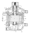
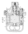
- Figures 1 to 6 show a first embodiment of a gas compressor of variable volume according to the present invention.
- the gas compressor of Figures 1-6 comprises a compressor body 1, a casing 2 which is open at one end, and a front head 3 which is fixed to the open end face of the casing 2.
- the compressor body 1 is enclosed in a gas-tight manner within the casing 2 and front head 3.
- the compressor body 1 is composed of a cylinder 4 which is formed to have a generally elliptical inner periphery in cross section (although it may, if desired be circular in cross-section) and front and rear side blocks 5 and 6 which are respectively fixed to the opposite sides of the cylinder 4.
- a solid, cylindrical rotor 9 which is rotatable about an horizontal axis.
- the rotor 9 is fixed to or is integrated with a rotor shaft 7 and carries on its outer circumference five vanes 8 which are radially movable towards and away from the said outer circumference.
- the vanes 8, which engage the wall of the cylinder chamber 13, may thus be moved into and out of the compression space 8 a provided partly in the cylinder chamber 13.
- a generally disk-shaped rotary plate 10 which is capable of being moved angularly within a predetermined angular range.
- the rotary plate 10 is formed at its periphery with recesses 11 and is also formed with an intake port 16 through which communication is provided between communication holes 12 of the front side block 5 and the cylinder chamber 13.
- the rotary plate 10 moves clockwise so that the recesses 11 and intake port 16 reduce the effective volume of the compression space 8 a and thus raise the intake pressure of the cylinder chamber 13. Due to a rise of the intake pressure in a low-speed run, on the other hand, the rotary plate 10 can rotate so that the recesses 11 and intake port 16 may move counter-clockwise to maximize the said volume.
- a coolant gas which is introduced under a low pressure from an intake port 14 formed in the front head 3 is sucked into an intake chamber 15, as indicated by solid arrows in Figure 1 and thus into the cylinder chamber 13 via both the communication holes 12, which are formed in the front side block at diametrically opposed positions, and the intake port 16.
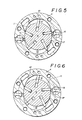
- the gas is then compressed to a high pressure and is supplied through a discharge port 17 ( Figures 5 and 6 ) and a discharge valve 18 and further through a communication hole.
- the latter extends into the gap between the cylinder 4 and the inner periphery of the casing 2 and is formed in the rear side block 6 at an angle of 90 degrees to the communication holes 12, so as to extend to an oil separator 19 which is formed at the back of the block 6.
- the compressed gas is discharged, as indicated by a broken line in Figure 1, from the rear space of the casing 2 to the outside through a discharge port 20.
- the compressor body 1 is provided with an oil reservoir 35 the oil in which is maintained under a high pressure by means not shown, the oil being used as a drive source for driving the rotary plate 10.
- An hydraulic piston 21 is slidably mounted in a cylindrical portion 3 a of the front head 3 so that it can be moved towards and away from the axis of the compressor in a direction perpendicular to the said axis.
- the hydraulic piston 21 has a head 21 a disposed within the intake chamber 15, the latter being defined by the front head 3 and the front side block 5.
- the hydraulic piston 21 has a shoulder 21 b which defines with the cylindrical portion 3 a a gap 22 into which is introduced the oil from the reservoir 35 at the side of the compressor via an oil passage 23 formed in the front head 3.
- the head 3 is provided with a spool valve 24 for opening or closing the oil passage 23.
- the spool valve 24 comprises a hollow piston 25 which is slidably mounted in a cylindrical portion 3 b of the front head 3 so as to be movable towards and away from the intake chamber 15.
- One end of the spool valve 24 is open to the intake chamber 15, the other end thereof being open to the outside.
- a spring 26 is disposed in the hollow piston 25 so as to urge the latter towards the intake chamber 15 with a predetermined spring force.
- the hollow piston 25 of the spool valve 24 is caused to move back and forth in the front head 3 in accordance with the difference between the intake pressure in the intake chamber 15 and the force of the spring 26.
- This back and forth movement of the hollow piston 25 causes an annular communication groove 27 a therein to be moved into and out of a position in which it establishes communication between portions 23 a and 23 b of the oil passage 23.
- the hydraulic piston 21 is formed at its leading end with an engagement portion 28 in which is loosely fitted the leading end of a drive pin 29.
- the latter is fixed in the rotary plate 10 so as to extend at right angles therefrom and into the intake chamber 15.
- the drive pin 29 extends through a cam groove 30 which is formed in an arcuate shape in the front side block 5.
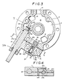
- the hydraulic piston 21 and the hollow piston 25 of the spool valve 24 are located in the positions shown in Figure 3, and in this case the rotary plate 10 will be located in the position shown in Figure 5.
- the intake pressure in the intake chamber 15 first drops to a level lower than the predetermined level so that the hollow piston 25 of the spool valve 24 moves in the direction indicated by an arrow X.
- the intake pressure in the intake chamber 15 becomes weaker than the force of the spring 26 in the hollow piston 25, there will be communication between the portions 23 a and 23 b of the oil passage 23 via the communication groove 27 a .
- the oil which is under pressure in the oil reservoir 35 and which is throttled in the course of passing through the oil passage 23 passes to the axial clearance between the hydraulic piston 21 and the cylindrical portion 3 a to fill up the gap 22 at the back of the hydraulic piston 21.
- the hydraulic piston 21 is thus caused to move towards the intake chamber 15 by the oil pressure, at a speed which is controlled to a suitable value, so as to push the drive pin 29 which is fitted loosely in the engagement portion 28 of the hydraulic piston 21 in the direction indicated by an arrow Y.
- the drive pin 29 rotates on its axis while passing along the cam groove 30 so that the rotary plate 10 also rotates to the position shown in Figure 6 because it is secured to (or integral with) the drive pin 29.
- the hollow piston 25 is caused to retract so as to establish communication between an oil passage 23 c and a communication groove 27 b .
- the oil fed to the gap 22 is thus returned to a pressure chamber (not shown), thus enabling the hydraulic piston 21 to retract.
- the coolant confining volume of the compression space is enlarged.
- the hollow piston 25 of the spool valve 24 has already retracted to the position shown in Figure 3, while blocking the communication between the oil passages 23 a and 23 b , so that no oil is fed to the gap 22.
- a stopper 36 is provided for controlling the stroke of the hollow piston 25 of the spool valve 24.
- a thrust bearing 31 is mounted on one side of the rotary plate 10 for smoothing rotational motion of the latter.
- the angular position of the rotary plate 10 is continuously set by the intake pressure of the intake chamber 15 so as to set the intake port 16, which communicates with the cylinder chamber 13, relative to the communication holes 12 which are formed in the front side block 5 so that the effective volume of the compression space 8 a varies in accordance with the state of operation of the gas compressor.
- the rotary plate 10 is always set such that the gas entering the compression space 8 a is at a substantially constant pressure.
- Figure 7 The construction of Figure 7 is generally similar to that of Figures 1-6 and for this reason will not be described in detail, like reference numerals indicating like parts.
- a hydraulic piston 21' is employed which, as in the embodiment of Figures 1-6, extends at right angles to the axis of the compressor and has one end thereof open to the intake chamber 15.
- the hydraulic piston 21' has its side formed with a rack portion 32 which meshes with an intermediate pinion 33.
- the intermediate pinion 33 is rotatably mounted in a hole which extends through a front side block 5'.
- the pinion 34 meshes with the intermediate pinion 33.
- the position of the piston 21' is set by the difference between the intake pressure of the intake chamber 15 and the force of the spring 26 of the spool valve 24. Movement of the piston 21' causes the intermediate pinion 33 which meshes with the rack portion 32, to be correspondingly rotated. Such rotation of the intermediate pinion 33, moreover, causes rotation of the pinion 34 so that the rotary plate 10' is rotated through a predetermined angle because the plate 10' is made integral with the pinion 34.
- an intake port (not shown) in the rotary plate 10' is moved so that the volume of the compression space for the coolant gas can be made continuously variable so as to hold the intake pressure at a constant level.
- the gas compressors shown in the drawings are of the variable volume type which can always be run at an optimum volume by rotating the rotary plate 10, 10' mounted on the inner side of the front side block 5, 5' so as to hold the intake pressure at a constant level at all times in accordance with the change in the intake pressure of the intake chamber 15 due to the running conditions, thereby to control the effective volume for the compression in the cylinder chamber 13.
- the hydraulic piston 21, 21' is moved back and forth by the operation of the spool valve 24 which is responsive to the intake pressure in the intake chamber 15 so that the rotary plate 10, 10' is rotated by movement of the hydraulic piston 21, 21'.
- a gas compressor according to the present invention can be made simpler than that in which the rotary plate is controlled by a temperature responsive system. Moreover, the control of the rotary plate can be compact because the control does not comprise a motor attached to the compressor.
Landscapes
- Engineering & Computer Science (AREA)
- Mechanical Engineering (AREA)
- General Engineering & Computer Science (AREA)
- Applications Or Details Of Rotary Compressors (AREA)
- Rotary Pumps (AREA)
Applications Claiming Priority (2)
| Application Number | Priority Date | Filing Date | Title |
|---|---|---|---|
| JP60194061A JPS6255488A (ja) | 1985-09-03 | 1985-09-03 | 気体圧縮機 |
| JP194061/85 | 1985-09-03 |
Publications (2)
| Publication Number | Publication Date |
|---|---|
| EP0217533A1 true EP0217533A1 (de) | 1987-04-08 |
| EP0217533B1 EP0217533B1 (de) | 1990-05-23 |
Family
ID=16318297
Family Applications (1)
| Application Number | Title | Priority Date | Filing Date |
|---|---|---|---|
| EP86306525A Expired - Lifetime EP0217533B1 (de) | 1985-09-03 | 1986-08-22 | Gasverdichter mit variabler Durchflussmenge |
Country Status (5)
| Country | Link |
|---|---|
| US (1) | US4881878A (de) |
| EP (1) | EP0217533B1 (de) |
| JP (1) | JPS6255488A (de) |
| KR (1) | KR870003310A (de) |
| DE (1) | DE3671504D1 (de) |
Families Citing this family (5)
| Publication number | Priority date | Publication date | Assignee | Title |
|---|---|---|---|---|
| DE3709711C2 (de) * | 1986-03-28 | 1997-03-27 | Seiko Seiki Kk | Kompressor |
| US5035584A (en) * | 1986-10-31 | 1991-07-30 | Atsugi Motor Parts Co., Ltd. | Variable-delivery vane-type rotary compressor |
| US5364235A (en) * | 1993-09-27 | 1994-11-15 | Zexel Usa Corporation | Variable capacity vane compressor with axial pressure device |
| US5492450A (en) * | 1993-09-27 | 1996-02-20 | Zexel Usa Corporation | Control valve for variable capacity vane compressor |
| KR100360655B1 (ko) * | 2000-12-13 | 2002-11-13 | 현대자동차주식회사 | 라디에이터 캡의 안전 장치 |
Citations (7)
| Publication number | Priority date | Publication date | Assignee | Title |
|---|---|---|---|---|
| GB729070A (en) * | 1952-11-17 | 1955-05-04 | Clifford Aero & Auto Ltd | Rotary hydraulic motors |
| FR1173436A (fr) * | 1956-04-06 | 1959-02-25 | Borg Warner | Pompe à engrenage avec denture intérieure et denture extérieure |
| US3120814A (en) * | 1959-10-21 | 1964-02-11 | Mueller Otto | Variable delivery and variable pressure vane type pump |
| US3418937A (en) * | 1966-11-04 | 1968-12-31 | White Motor Corp | Radial piston pump |
| US3434428A (en) * | 1967-06-05 | 1969-03-25 | White Motor Corp | Intake control for multiple piston pump |
| DE2057750A1 (de) * | 1969-11-27 | 1971-06-09 | Stal Refrigeration Ab | Drehkolbenmaschine mit Rueckstroemungsregelung |
| US4060343A (en) * | 1976-02-19 | 1977-11-29 | Borg-Warner Corporation | Capacity control for rotary compressor |
Family Cites Families (12)
| Publication number | Priority date | Publication date | Assignee | Title |
|---|---|---|---|---|
| US3224662A (en) * | 1965-02-16 | 1965-12-21 | Oldberg Oscar | Compressor modulating system |
| US3451614A (en) * | 1967-06-14 | 1969-06-24 | Frick Co | Capacity control means for rotary compressors |
| US4330999A (en) * | 1977-07-27 | 1982-05-25 | Kabushiki Kaisha Toyoda Jidoshokki Seisakusho | Refrigerant compressor |
| US4137018A (en) * | 1977-11-07 | 1979-01-30 | General Motors Corporation | Rotary vane variable capacity compressor |
| JPS5569787A (en) * | 1978-11-21 | 1980-05-26 | Central Jidosha Kogyo Kk | Cooling medium compressor for vehicle |
| US4421462A (en) * | 1979-12-10 | 1983-12-20 | Jidosha Kiki Co., Ltd. | Variable displacement pump of vane type |
| JPS5791394A (en) * | 1980-11-28 | 1982-06-07 | Matsushita Electric Ind Co Ltd | Rotary refrigerant compressor |
| JPS58155287A (ja) * | 1982-03-09 | 1983-09-14 | Nippon Soken Inc | 冷凍装置 |
| JPS5930918A (ja) * | 1982-08-16 | 1984-02-18 | Kanebo Ltd | 炭素繊維の製造方法 |
| JPS6062690A (ja) * | 1983-09-16 | 1985-04-10 | Toyoda Autom Loom Works Ltd | 部分負荷運転の可能なロ−タリ圧縮機 |
| JPS60171989U (ja) * | 1984-04-25 | 1985-11-14 | 株式会社ボッシュオートモーティブ システム | カ−ク−ラ用ベ−ン型圧縮機 |
| US4726740A (en) * | 1984-08-16 | 1988-02-23 | Kabushiki Kaisha Toyoda Jidoshokki Seisakusho | Rotary variable-delivery compressor |
-
1985
- 1985-09-03 JP JP60194061A patent/JPS6255488A/ja active Pending
-
1986
- 1986-08-22 DE DE8686306525T patent/DE3671504D1/de not_active Expired - Lifetime
- 1986-08-22 EP EP86306525A patent/EP0217533B1/de not_active Expired - Lifetime
- 1986-08-29 US US06/902,419 patent/US4881878A/en not_active Expired - Lifetime
- 1986-09-02 KR KR1019860007314A patent/KR870003310A/ko not_active Withdrawn
Patent Citations (7)
| Publication number | Priority date | Publication date | Assignee | Title |
|---|---|---|---|---|
| GB729070A (en) * | 1952-11-17 | 1955-05-04 | Clifford Aero & Auto Ltd | Rotary hydraulic motors |
| FR1173436A (fr) * | 1956-04-06 | 1959-02-25 | Borg Warner | Pompe à engrenage avec denture intérieure et denture extérieure |
| US3120814A (en) * | 1959-10-21 | 1964-02-11 | Mueller Otto | Variable delivery and variable pressure vane type pump |
| US3418937A (en) * | 1966-11-04 | 1968-12-31 | White Motor Corp | Radial piston pump |
| US3434428A (en) * | 1967-06-05 | 1969-03-25 | White Motor Corp | Intake control for multiple piston pump |
| DE2057750A1 (de) * | 1969-11-27 | 1971-06-09 | Stal Refrigeration Ab | Drehkolbenmaschine mit Rueckstroemungsregelung |
| US4060343A (en) * | 1976-02-19 | 1977-11-29 | Borg-Warner Corporation | Capacity control for rotary compressor |
Also Published As
| Publication number | Publication date |
|---|---|
| JPS6255488A (ja) | 1987-03-11 |
| DE3671504D1 (de) | 1990-06-28 |
| EP0217533B1 (de) | 1990-05-23 |
| US4881878A (en) | 1989-11-21 |
| KR870003310A (ko) | 1987-04-16 |
Similar Documents
| Publication | Publication Date | Title |
|---|---|---|
| EP0809032B1 (de) | Spiralverdichter mit Einrichtung zur Kapazitätsänderung | |
| US4410299A (en) | Compressor having functions of discharge interruption and discharge control of pressurized gas | |
| US4685866A (en) | Variable displacement wobble plate type compressor with wobble angle control unit | |
| US5562426A (en) | Scroll type refrigerant compressor | |
| US4846632A (en) | Variable displacement vane compressor | |
| JPH0794832B2 (ja) | 回転式圧縮機 | |
| US4551080A (en) | Variable displacement sliding vane pump/hydraulic motor | |
| US4472119A (en) | Capacity control for rotary compressor | |
| US4516919A (en) | Capacity control of rotary vane apparatus | |
| EP0220801A1 (de) | Gasverdichter mit veränderlicher Fördermenge | |
| US4619595A (en) | Capacity control device for compressor | |
| EP0217533B1 (de) | Gasverdichter mit variabler Durchflussmenge | |
| US4514157A (en) | Rotary vane compressor | |
| KR101215898B1 (ko) | 2 스피드 압축기 어셈블리 및 개방 구동 스크롤 기계 | |
| US4522573A (en) | Variable delivery vane compressor | |
| KR910001182B1 (ko) | 가변용랑 압축기 | |
| US5035584A (en) | Variable-delivery vane-type rotary compressor | |
| US4753071A (en) | Self-powered rotating-cylinder type linear actuator utilizing rotation-generated centrifugal head for piston positioning | |
| JPS6111401A (ja) | 回転型流体機械 | |
| JP2539545Y2 (ja) | ロータリコンプレッサ | |
| JPH0752393Y2 (ja) | 可変容量型気体圧縮機 | |
| JPS6347677Y2 (de) | ||
| JPH1026092A (ja) | 圧縮機 | |
| JP3383602B2 (ja) | 気体圧縮機 | |
| JPS639689A (ja) | 可変容量型ベ−ンポンプ |
Legal Events
| Date | Code | Title | Description |
|---|---|---|---|
| PUAI | Public reference made under article 153(3) epc to a published international application that has entered the european phase |
Free format text: ORIGINAL CODE: 0009012 |
|
| AK | Designated contracting states |
Kind code of ref document: A1 Designated state(s): DE FR GB |
|
| 17P | Request for examination filed |
Effective date: 19870911 |
|
| 17Q | First examination report despatched |
Effective date: 19881014 |
|
| GRAA | (expected) grant |
Free format text: ORIGINAL CODE: 0009210 |
|
| AK | Designated contracting states |
Kind code of ref document: B1 Designated state(s): DE FR GB |
|
| REF | Corresponds to: |
Ref document number: 3671504 Country of ref document: DE Date of ref document: 19900628 |
|
| ET | Fr: translation filed | ||
| PLBE | No opposition filed within time limit |
Free format text: ORIGINAL CODE: 0009261 |
|
| STAA | Information on the status of an ep patent application or granted ep patent |
Free format text: STATUS: NO OPPOSITION FILED WITHIN TIME LIMIT |
|
| 26N | No opposition filed | ||
| REG | Reference to a national code |
Ref country code: FR Ref legal event code: D6 |
|
| REG | Reference to a national code |
Ref country code: GB Ref legal event code: IF02 |
|
| REG | Reference to a national code |
Ref country code: FR Ref legal event code: TP |
|
| PGFP | Annual fee paid to national office [announced via postgrant information from national office to epo] |
Ref country code: FR Payment date: 20040810 Year of fee payment: 19 |
|
| PGFP | Annual fee paid to national office [announced via postgrant information from national office to epo] |
Ref country code: GB Payment date: 20040818 Year of fee payment: 19 |
|
| PGFP | Annual fee paid to national office [announced via postgrant information from national office to epo] |
Ref country code: DE Payment date: 20040902 Year of fee payment: 19 |
|
| PG25 | Lapsed in a contracting state [announced via postgrant information from national office to epo] |
Ref country code: GB Free format text: LAPSE BECAUSE OF NON-PAYMENT OF DUE FEES Effective date: 20050822 |
|
| PG25 | Lapsed in a contracting state [announced via postgrant information from national office to epo] |
Ref country code: DE Free format text: LAPSE BECAUSE OF NON-PAYMENT OF DUE FEES Effective date: 20060301 |
|
| GBPC | Gb: european patent ceased through non-payment of renewal fee |
Effective date: 20050822 |
|
| PG25 | Lapsed in a contracting state [announced via postgrant information from national office to epo] |
Ref country code: FR Free format text: LAPSE BECAUSE OF NON-PAYMENT OF DUE FEES Effective date: 20060428 |
|
| REG | Reference to a national code |
Ref country code: FR Ref legal event code: ST Effective date: 20060428 |