EP0217595A2 - Distributeur - Google Patents
Distributeur Download PDFInfo
- Publication number
- EP0217595A2 EP0217595A2 EP86307171A EP86307171A EP0217595A2 EP 0217595 A2 EP0217595 A2 EP 0217595A2 EP 86307171 A EP86307171 A EP 86307171A EP 86307171 A EP86307171 A EP 86307171A EP 0217595 A2 EP0217595 A2 EP 0217595A2
- Authority
- EP
- European Patent Office
- Prior art keywords
- chamber
- dispenser
- dilution
- dilution chamber
- outlet
- Prior art date
- Legal status (The legal status is an assumption and is not a legal conclusion. Google has not performed a legal analysis and makes no representation as to the accuracy of the status listed.)
- Withdrawn
Links
Images


Classifications
-
- E—FIXED CONSTRUCTIONS
- E03—WATER SUPPLY; SEWERAGE
- E03D—WATER-CLOSETS OR URINALS WITH FLUSHING DEVICES; FLUSHING VALVES THEREFOR
- E03D9/00—Sanitary or other accessories for lavatories ; Devices for cleaning or disinfecting the toilet room or the toilet bowl; Devices for eliminating smells
- E03D9/02—Devices adding a disinfecting, deodorising, or cleaning agent to the water while flushing
- E03D9/03—Devices adding a disinfecting, deodorising, or cleaning agent to the water while flushing consisting of a separate container with an outlet through which the agent is introduced into the flushing water, e.g. by suction ; Devices for agents in direct contact with flushing water
- E03D9/033—Devices placed inside or dispensing into the cistern
- E03D9/038—Passive dispensers, i.e. without moving parts
-
- E—FIXED CONSTRUCTIONS
- E03—WATER SUPPLY; SEWERAGE
- E03D—WATER-CLOSETS OR URINALS WITH FLUSHING DEVICES; FLUSHING VALVES THEREFOR
- E03D9/00—Sanitary or other accessories for lavatories ; Devices for cleaning or disinfecting the toilet room or the toilet bowl; Devices for eliminating smells
- E03D9/02—Devices adding a disinfecting, deodorising, or cleaning agent to the water while flushing
- E03D2009/024—Devices adding a disinfecting, deodorising, or cleaning agent to the water while flushing using a solid substance
Definitions
- This invention relates to dispensers.
- the invention consists in a dispenser comprising a body having a storage chamber to substantially retain a selected dispensable material, a dilution chamber in communication with said storage chamber, said communication being such that fluid flow from said storage chamber to said dilution chamber is restricted, an outlet from said dilution chamber, flow controlling means associated with said outlet, an inlet to said dilution chamber to admit fluid from outside said body to said dilution chamber the construction and arrangement being such that said selected dispensable material is retained in said dilution chamber in a diluted state.
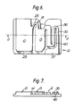
- a dispenser 1 may be formed so as to provide various conduits passageways and chambers as will be herein described.
- the passageways, conduits and chambers may be formed in any desired manner but in the preferred embodiment are formed from shaped plastic sheet material and this may be achieved for example by vacuum forming.
- One of these members for example the central panel 3 may be extended one at one edge to form a sheet area 6 which can be utilized for mounting the dispenser in use.
- a double dispensing system is provided but it will be apparent that by using one half of the construction a single dispensing system is provided.
- the dispenser contained between the panels 2 and 3 will now be described.
- the construction includes a storage chamber 10 into which a dispensable material can be positioned.
- the dispenable material will be selected so as to be appropriate to the use to which the dispenser is to be put.
- the material may be intended to be dispensed or discharged into for example a lavatory bowl and in these circumstances the material may comprise for example a disinfectant and/or an antiseptic and/or a colourant and this may be provided in the form of for example a liquid or crystals able to dissolve particularly in water or a block for example block 11 from which the material can leach.
- the block 11 has a piece of foamed plastics material 12 positioned thereover.
- the construction also provides an intermediate or dilution chamber 13 which is in communication with the storage chamber 10 in a manner such that fluid flow from the storage chamber 10 to the dilution chamber 13 is of a restricted nature.
- a conduit 14 of a relatively small aperture size is provided having openings 15 into the storage chamber 10.
- a replenishment reservoir 16 which may have a further opening 17 into the upper end in use of the storage chamber 10.
- the chamber, conduits and the like may be formed by suitable vacuum formed shapes in the members 2 and 3 which when formed of a plastics material can be joined for example as shown at enlarged corner 17 by any suitable technique such as for example solvent welding, sonic welding or otherwise as desired.
- the conduit 14 continues into the dilution chamber 13 passing through an elbow or bend 18 the uppermost point on the inner surface 19 of which is below in use the bottom 20 of the replenishment chamber 16 so that in use during a desired time of the cycle of the device as will be described further herein liquid will flow from the replenishment chamber 16 to the dilution chamber 13.
- An opening to the dilution chamber 13 is provided for example at 21 through which air and/or liquid may move at selected times in the cycle.
- the chamber 10 may be formed or outlined by a raised rib 22 on centre panel 3 into which the smaller entrances 15 and 17 are provided and the remainder of the conduit 14 may be defined by a raised portion 23 in front panel 2.
- the front panel 2 extends downwardly at 24 so that the elbow 19 is defined by a downwardly extending wall 25 in the front panel 2.
- the dilution chamber 13 is somewhat smaller in size than the storage chamber 10.
- An outlet is provided from the dilution chamber 13 and the outlet preferably includes a dispensing chamber 30 which is of smaller dimensions than the dilution chamber 13 and which is in communication with the dilution chamber 13 at two points.
- a relatively unrestricted connection is provided at an upper level at 31 for example and a smaller or restricted connection is provided at the lower end for example at 32.
- the entranceway at 21 is in communication with the passageway at 31 so that liquid but more particularly air interchange can take place into the dispensing chamber 30.
- From the dispensing chamber 30 is provided an outlet for example by means of a conduit 35 and flow controlling means are associated with the outlet.
- the flow controlling means desirably comprise a siphon having its upper point at 36 and which has a discharge end at 37. It is also desireable to provide the discharge end 37 in the form of a chamber.
- the discharge chamber 37 is therefore shaped to provide at least one outlet 38 by which the material in the dispensing chamber 30 may be despensed into for example a toilet cistern during flushing.
- the passageway 35 may be defined by a downwardly extending rib 40 on the member 2 and similar downwardly extending portions around the passageway 35.
- the rib 40 must extend to a position above the position of the downwardly extending rib 41 between the chambers 13 and 30 so that the upper end 36 of the passageway 35 can form an airlook at the required time as will be described further herein.
- the purpose of the dilution chamber 13 is to hold and mix material flowing from the storage chamber 10 in a diluted form the dilution being achieved by means of liquid in particular water drawn from outside the dispenser into the dilution chamber 13 through the aperture at 21.
- the volumn of the replenishment chamber 16 should not exceed the volumn of the dilution chamber 13 although they can be of substantially the same size but in the preferred embodiment the volumn of the replenishment chamber 16 is somewhat less than the volumn of the dilution chamber 13.
- the members 2 and 3 and also the other members herein described may be formed of a suitable plastics material such as polyvinylchloride which as stated above can be formed by vacuum moulding or could be formed if desired from injection moulding.
- the members include suitable peripheral flanges such as peripheral flange 50 on member 2 and 51 on member 3 to enable interconnections to take place.
- the member 3 also preferably includes a downwardly depending skirt 52 in particular to house the second dispensing system as will be described further herein. Adherence can be achieved as above described for example by gluing, radio frequency welding or otherwise as desired. Connections can be formed at all areas where for example downwardly extending ribs such as 40 and 41 bare on a flat surface and it is believed that this will be the most suitable arrangement in practice.
- the dispenser of the invention is placed in a situation where there is a rise and fall in water levels such as for example in situations such as hydroponic or other horticultural applications, cleaning or dispensing materials in the dairy industry, and to spa pools for example as a dispensable material is able to be extraneously supplied to the storage chamber 10.
- a substantially constant flow an apparatus is required to be introduced to induce breaks into the flow so as to enable the rise and fall required for the construction to operate.
- the dispenser of the invention is placed into a toilet cistern so that the chamber 16 is positioned below the water level at its highest position and so that the outlet 38 is placed above the water level at its lowest position.
- the siphon formed by conduit 35 will begin to operate drawing diluted material contained in the chamber 30 through the siphon and into the chamber 37 where it will be taken by the flushing water as the flushing water continues to fall. Because of the restricted nature of the orifice at 32 flow through the orifice 32 is not sufficiently quick to enable emptying of the dilution chamber 13 by the siphon before the chamber 30 emties and the siponic action will therefore cease. Thus the orifice size at 32 must be less than the minimum diameter of the conduit at 35.
- the water in the dilution chamber 13 will then be replenished by water retained in the replenishment chamber 16 which will move through the conduit 14 and some material from the storage chamber 10 will be picked up through the conduit 15.
- the water in the chamber 16 will not completely fill the dilution chamber 13 and may for example about half fill that chamber.
- water level begins to rise in the cistern water will begin to enter the conduit 35 from the outlet end pushing air in the siphon through the dispensing chamber 30 and out through the outlet 21.
- the time that the water is rising there will be also passage of the liquid leaving the dilution chamber 13 through the conduit at 32 thereby passing material into the dispensing chamber 30.
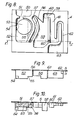
- a second dispenser cistern is provided which is substantially shown in figures 8, 9 and 10.
- a replenishment chamber 50 feeds through its bottom outlet 51 a storage chamber 52 into which a block 53 of leachable material such as chlorine is provided.
- the chlorine block 53 may rest on indentations or supports 54 and 55.
- An outlet 56 is provided from the storage chamber passing around an elbow 57 which substantially approximates the elbow at 18.
- a dilution chamber 58 is provided and an upper connection 59 and a lower restricted orifice 60 to a discharge chamber 61 are also provided. Again an outlet siphon passage is provided at 62 feeding a discharge chamber 63.
- the positioning of the elemennts in this construction is substantially as described for the first dispensing system.
- This dispensing system may be formed for example by a vacuum form sheet as before and the chambers may be closed by the plate or cover 5. Which may be adhered to the plate 4 substantially as described in the previous construction.
- An aperture 63 (shown pecked in figure 8) is provided to allow replenishment of the chamber 58 during refilling of the cistern and also to allow air ingress and egress as required. It is clear from figure 2 that by suitably shaping the chambers in both dispensing systems they can be caused to fit back to back in an effective manner to reduce the thickness of the double dispensing system.
- a dispenser in which a substantially diluted antiseptic disinfectant cleaner or the like may be place into the bowl of a toilet with the flushing water or in which material may be dispensed in other situations having a liquid such as water flow.
- a reservoir of the material to be dispensed will remain available for a substantial period of time before replacement of the dispenser is required.
- the material supplied from the or each storage chamber 2 is substantially a metered amount because of the use of a dispensing chamber 30 or 61.
- the construction also enables in one embodiment the provision to dispense two separate dispensable materials.
Landscapes
- Health & Medical Sciences (AREA)
- Public Health (AREA)
- Epidemiology (AREA)
- Life Sciences & Earth Sciences (AREA)
- Engineering & Computer Science (AREA)
- Hydrology & Water Resources (AREA)
- Water Supply & Treatment (AREA)
- Bidet-Like Cleaning Device And Other Flush Toilet Accessories (AREA)
- Accessories For Mixers (AREA)
- Devices For Dispensing Beverages (AREA)
Applications Claiming Priority (2)
| Application Number | Priority Date | Filing Date | Title |
|---|---|---|---|
| NZ21353385 | 1985-09-18 | ||
| NZ213533 | 1985-09-18 |
Publications (2)
| Publication Number | Publication Date |
|---|---|
| EP0217595A2 true EP0217595A2 (fr) | 1987-04-08 |
| EP0217595A3 EP0217595A3 (fr) | 1987-06-03 |
Family
ID=19921370
Family Applications (1)
| Application Number | Title | Priority Date | Filing Date |
|---|---|---|---|
| EP86307171A Withdrawn EP0217595A3 (fr) | 1985-09-18 | 1986-09-17 | Distributeur |
Country Status (6)
| Country | Link |
|---|---|
| US (1) | US4823410A (fr) |
| EP (1) | EP0217595A3 (fr) |
| JP (1) | JPS62117925A (fr) |
| AU (1) | AU584747B2 (fr) |
| IN (1) | IN168353B (fr) |
| ZA (1) | ZA867082B (fr) |
Cited By (1)
| Publication number | Priority date | Publication date | Assignee | Title |
|---|---|---|---|---|
| WO2008001042A1 (fr) * | 2006-06-30 | 2008-01-03 | Reckitt Benckiser Inc. | distributeur de type à cartouche |
Families Citing this family (3)
| Publication number | Priority date | Publication date | Assignee | Title |
|---|---|---|---|---|
| GB8700473D0 (en) * | 1987-01-09 | 1987-02-11 | Kiwi Pacific Pty Ltd Nicholas | Additive device for toilet flush water |
| USRE35857E (en) * | 1992-04-08 | 1998-07-21 | Hydroplan Engineering Ltd. | Irrigation systems |
| USD400642S (en) | 1997-05-27 | 1998-11-03 | The Clorox Company | Toilet tank dispenser |
Family Cites Families (10)
| Publication number | Priority date | Publication date | Assignee | Title |
|---|---|---|---|---|
| US2045473A (en) * | 1936-03-02 | 1936-06-23 | Keillor Joseph Dempster | Cleansing and deodorizing device for closet bowls |
| US4171546A (en) * | 1977-10-21 | 1979-10-23 | The Procter & Gamble Company | Passive dosing dispenser |
| US4281421A (en) * | 1979-03-12 | 1981-08-04 | The Procter & Gamble Company | Passive dosing dispenser with improved hypochlorite cake |
| US4305162A (en) * | 1980-11-10 | 1981-12-15 | The Procter & Gamble Company | Passive dosing dispenser employing captive air bubble to provide product isolation |
| EP0086857A1 (fr) * | 1982-02-23 | 1983-08-31 | American Cyanamid Company | Emballage distributeur doseur automatique de produit d'entretien soluble dans le réservoir et la cuvette |
| US4438534A (en) * | 1982-03-03 | 1984-03-27 | The Drackett Company | Passive dispenser |
| US4729880A (en) * | 1982-12-23 | 1988-03-08 | The Procter & Gamble Company | Article for maintaining more even concentrations of bleach in a passive dosing dispenser |
| EP0114428A1 (fr) * | 1982-12-23 | 1984-08-01 | THE PROCTER & GAMBLE COMPANY | Article et procédé pour maintenir plus uniformément une concentration d'un moyen javellisant dans un doseur passif |
| US4480342A (en) * | 1983-01-14 | 1984-11-06 | The Drackett Company | Passive dispenser |
| US4558471A (en) * | 1984-07-20 | 1985-12-17 | The Procter & Gamble Company | Passive dosing dispenser featuring high strength initial cleaning action |
-
1986
- 1986-09-16 US US06/907,870 patent/US4823410A/en not_active Expired - Fee Related
- 1986-09-17 EP EP86307171A patent/EP0217595A3/fr not_active Withdrawn
- 1986-09-17 ZA ZA867082A patent/ZA867082B/xx unknown
- 1986-09-18 JP JP61218249A patent/JPS62117925A/ja active Pending
- 1986-09-18 AU AU62902/86A patent/AU584747B2/en not_active Ceased
- 1986-09-19 IN IN742/MAS/86A patent/IN168353B/en unknown
Cited By (3)
| Publication number | Priority date | Publication date | Assignee | Title |
|---|---|---|---|---|
| WO2008001042A1 (fr) * | 2006-06-30 | 2008-01-03 | Reckitt Benckiser Inc. | distributeur de type à cartouche |
| AU2007263627B2 (en) * | 2006-06-30 | 2011-03-03 | Reckitt Benckiser Llc | Cartridge-type dispenser |
| US8444927B2 (en) | 2006-06-30 | 2013-05-21 | Reckitt Benckiser Llc | Cartridge-type dispenser |
Also Published As
| Publication number | Publication date |
|---|---|
| JPS62117925A (ja) | 1987-05-29 |
| AU6290286A (en) | 1987-03-19 |
| AU584747B2 (en) | 1989-06-01 |
| EP0217595A3 (fr) | 1987-06-03 |
| US4823410A (en) | 1989-04-25 |
| ZA867082B (en) | 1987-05-27 |
| IN168353B (fr) | 1991-03-16 |
Similar Documents
| Publication | Publication Date | Title |
|---|---|---|
| US5584079A (en) | Programmable dispenser | |
| EP0001671B1 (fr) | Distributeur passif pour le dosage d'additifs pour réservoir de chasse d'eau | |
| EP0004990B1 (fr) | Distributeur-doseur utilisant une bulle d'air pour obtenir un isolement | |
| US4064572A (en) | Level actuated apparatus for delivering chemicals | |
| US4251012A (en) | Passive liquid dosing dispenser | |
| US4534071A (en) | Automatic dispenser for disinfectant and bowl cleaning fluid | |
| US4186856A (en) | Self-priming passive dosing dispenser | |
| US4307474A (en) | Passive dosing dispenser exhibiting improved resistance to clogging | |
| US7073209B1 (en) | Passive sanitizing-tablet dispensing device | |
| US5429270A (en) | Process and apparatus for dispensing liquids to a remote bathroom fixture | |
| US4823410A (en) | Dispensers | |
| US4745638A (en) | Passive dispenser having delayed discharge | |
| US6341385B1 (en) | Toilet bowl fluid dispensing system | |
| US6820287B2 (en) | Down-stroke dispenser | |
| CA1274490A (fr) | Appareil debiteur | |
| US2614265A (en) | Disinfecting device | |
| EP3114286B1 (fr) | Apparail sanitaire comprenant un dispositif de distribution | |
| EP1426505A2 (fr) | Distributeur universel de liquide d'assainissement pour des résérvoirs d'eau ou similaire, en particulier des chasses d'eau de toilette | |
| US2888685A (en) | Toilet deodorizing device | |
| US20050204459A1 (en) | Dispenser for toilet cleaner solids of liquids | |
| JP3775507B2 (ja) | 水洗トイレ用薬剤供給具 | |
| JPS6192231A (ja) | 水洗便所の便器を洗浄するための適量分配器 | |
| US4821346A (en) | Toilet bowl cleaning composition dispenser | |
| EP1721049B1 (fr) | Systeme de generation de mousse | |
| JP3015390U (ja) | 水洗トイレの消毒剤放出量自動制御装置 |
Legal Events
| Date | Code | Title | Description |
|---|---|---|---|
| PUAI | Public reference made under article 153(3) epc to a published international application that has entered the european phase |
Free format text: ORIGINAL CODE: 0009012 |
|
| AK | Designated contracting states |
Kind code of ref document: A2 Designated state(s): AT BE CH DE FR GB IT LI LU NL SE |
|
| PUAL | Search report despatched |
Free format text: ORIGINAL CODE: 0009013 |
|
| AK | Designated contracting states |
Kind code of ref document: A3 Designated state(s): AT BE CH DE FR GB IT LI LU NL SE |
|
| 17P | Request for examination filed |
Effective date: 19871130 |
|
| 17Q | First examination report despatched |
Effective date: 19880923 |
|
| STAA | Information on the status of an ep patent application or granted ep patent |
Free format text: STATUS: THE APPLICATION IS DEEMED TO BE WITHDRAWN |
|
| 18D | Application deemed to be withdrawn |
Effective date: 19910403 |