EP0217681B1 - Temperatur- und druckempfindliche Vorrichtung, insbesondere zur Anwendung bei der Warnung und der Sicherung in Kühlungskreisen - Google Patents
Temperatur- und druckempfindliche Vorrichtung, insbesondere zur Anwendung bei der Warnung und der Sicherung in Kühlungskreisen Download PDFInfo
- Publication number
- EP0217681B1 EP0217681B1 EP19860401565 EP86401565A EP0217681B1 EP 0217681 B1 EP0217681 B1 EP 0217681B1 EP 19860401565 EP19860401565 EP 19860401565 EP 86401565 A EP86401565 A EP 86401565A EP 0217681 B1 EP0217681 B1 EP 0217681B1
- Authority
- EP
- European Patent Office
- Prior art keywords
- liquid
- pressure
- temperature
- diaphragm
- microswitch
- Prior art date
- Legal status (The legal status is an assumption and is not a legal conclusion. Google has not performed a legal analysis and makes no representation as to the accuracy of the status listed.)
- Expired - Lifetime
Links
- 238000001816 cooling Methods 0.000 title claims description 21
- 239000007788 liquid Substances 0.000 claims description 46
- 230000009471 action Effects 0.000 claims description 10
- 230000000694 effects Effects 0.000 claims description 10
- 230000009467 reduction Effects 0.000 claims description 4
- 238000002485 combustion reaction Methods 0.000 claims description 3
- 239000002775 capsule Substances 0.000 description 16
- 239000012528 membrane Substances 0.000 description 16
- 239000002826 coolant Substances 0.000 description 11
- 238000009835 boiling Methods 0.000 description 10
- LYCAIKOWRPUZTN-UHFFFAOYSA-N Ethylene glycol Chemical compound OCCO LYCAIKOWRPUZTN-UHFFFAOYSA-N 0.000 description 7
- XLYOFNOQVPJJNP-UHFFFAOYSA-N water Substances O XLYOFNOQVPJJNP-UHFFFAOYSA-N 0.000 description 5
- 230000006835 compression Effects 0.000 description 4
- 238000007906 compression Methods 0.000 description 4
- 239000000203 mixture Substances 0.000 description 4
- 238000010586 diagram Methods 0.000 description 3
- 239000004020 conductor Substances 0.000 description 2
- 238000002788 crimping Methods 0.000 description 2
- WGCNASOHLSPBMP-UHFFFAOYSA-N hydroxyacetaldehyde Natural products OCC=O WGCNASOHLSPBMP-UHFFFAOYSA-N 0.000 description 2
- 230000004044 response Effects 0.000 description 2
- 238000007789 sealing Methods 0.000 description 2
- 230000006978 adaptation Effects 0.000 description 1
- 230000005540 biological transmission Effects 0.000 description 1
- 238000010276 construction Methods 0.000 description 1
- 239000000110 cooling liquid Substances 0.000 description 1
- 238000006073 displacement reaction Methods 0.000 description 1
- 230000002452 interceptive effect Effects 0.000 description 1
- 230000007246 mechanism Effects 0.000 description 1
- 239000013528 metallic particle Substances 0.000 description 1
- 239000004071 soot Substances 0.000 description 1
Images

Classifications
-
- H—ELECTRICITY
- H01—ELECTRIC ELEMENTS
- H01H—ELECTRIC SWITCHES; RELAYS; SELECTORS; EMERGENCY PROTECTIVE DEVICES
- H01H37/00—Thermally-actuated switches
- H01H37/02—Details
- H01H37/32—Thermally-sensitive members
- H01H37/36—Thermally-sensitive members actuated due to expansion or contraction of a fluid with or without vaporisation
-
- H—ELECTRICITY
- H01—ELECTRIC ELEMENTS
- H01H—ELECTRIC SWITCHES; RELAYS; SELECTORS; EMERGENCY PROTECTIVE DEVICES
- H01H35/00—Switches operated by change of a physical condition
- H01H35/24—Switches operated by change of fluid pressure, by fluid pressure waves, or by change of fluid flow
Definitions
- the invention relates to a device, sensitive both to the temperature and to the pressure of a liquid and applicable in particular to warning or safety in pressurized liquid cooling circuits, in particular the circuits of sealed cooling for internal combustion engines, this device comprising two elements which are carried by the same hollow body and whose mutual approximation, caused by the reduction of the pressure and / or the increase in the temperature of the liquid, with intervention of means elastic, has the effect of closing an electrical alert or security circuit, the body comprising a first part intended to be immersed in the liquid and a second part intended to be mounted outside this liquid.
- the coolant can be water, a mixture of water and glycol, or any other suitable mixture.
- these sealed cooling circuits make it possible to increase the boiling temperature of the coolant and consequently the engine operating temperature and its efficiency.
- thermocontacts are used to warn the driver of the approach of the boiling temperature of the coolant.
- These thermocontacts are generally of the same type as those used in liquid cooling circuits which operate at ambient pressure, the thermocontact of the sealed circuit then being simply adjusted to a higher temperature due to the increase in the boiling temperature. . It follows that in the event of loss of sealing of the cooling circuit and consequently of reduction of the internal pressure of the circuit or even of cancellation of the overpressure with respect to atmospheric pressure, the boiling temperature thus lowered by coolant can be reached without the thermal switch being able to emit an alert or safety signal since it is set to a higher response pressure. This most often results in serious engine damage.
- thermocontacts capable of being adjusted to a temperature which varies as a function of pressure.
- FR-A-2,488,039 describes a thermal switch which meets the definition given in the preamble and which comprises a chamber of variable volume limited, relative to the cooling circuit, by a deformable capsule filled with a liquid and its vapor, this capsule being arranged, when it deforms against the action of an elastic means in the direction tending to increase the volume of the chamber, so as to bring about a mobile electrical contact up to a fixed electrical contact to thereby generate an alert or safety signal, the movable contact and the fixed contact being both located outside the above-mentioned chamber.
- the deformation of the capsule which is sensitive to both temperature and pressure, occurs with a constant offset between the pressures prevailing respectively between the exterior and the interior of the capsule. Consequently, whatever the external pressure, that is to say that the sealed cooling circuit is intact or has suffered more or less significant leaks, the warning temperature is automatically set to a value lower than the temperature boiling of the coolant, thanks to the compressibility of the vapor contained in the capsule, and this with a small but practically constant temperature difference.
- the object of the invention is to produce a device whose alert or safety temperature is automatically adjusted to such a value but in which the respective influences of temperature and pressure can be adjusted with more precision. It also aims to produce a device of this type which does not involve a capsule containing a liquid and its vapor, but a thermostat of the wax type, that is to say a thermostat which is already used in large series in the automotive industry (see for example GB-A-2,079,062) and in which the expansion of a wax, contained in a housing and possibly charged with metallic particles, causes a piston to come out of this housing more and more as the temperature of the wax rises.
- the invention also aims to improve the tightness of the device by eliminating any crossing of the wall by a sliding rod or the like, such as the rod 19 of FR-A-2,488,039.
- the subject of the invention is therefore a device, sensitive both to the temperature and to the pressure of a liquid and applicable in particular to warning or safety in pressurized liquid cooling circuits, in particular circuits sealed cooling systems for internal combustion engines, this device comprising two elements which are carried by the same hollow body and whose mutual approximation, caused by the decrease in pressure and / or increase in the temperature of the liquid, with intervention of elastic means, has the effect of closing an electrical alert or security circuit, the body comprising a first part intended to be immersed in the liquid and a second part intended to be mounted outside this liquid, characterized in that the first part of the body carries, on the one hand, a waterproof deformable membrane which isolates from the liquid the second part of the body and which tends to be pushed v ers this second part by the pressure of the liquid and against the action of first elastic means and, on the other hand, on the liquid side, the casing of a wax thermostat, the piston of which constitutes one of the two abovementioned elements, and tends, under the effect of the
- US-A-3,129,309 describes a switch sensitive to a gas pressure prevailing in a tank and compensated as a function of temperature, this switch comprising two caps. soot located outside the tank and connected one inside the tank, to assess the gas pressure, and the other to a sealed bulb placed inside the tank to assess the gas temperature.
- the membrane carries, on its face remote from the wax thermostat, a microswitch whose control finger is arranged so as to cooperate with the piston of the wax thermostat and thus constitutes the second of the above elements.
- the first elastic means are advantageously arranged so as to hold the microswitch against the membrane.
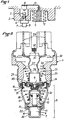
- the device comprises two elements 1 and 2 carried by the same body 3 and whose mutual approximation, caused by the reduction in pressure and / or the increase in temperature of a liquid such as the liquid from a sealed cooling circuit, has the effect of closing an electrical alert or safety circuit, the principle of which is well known and which will therefore not be described in detail.
- the elements 1 and 2 can constitute by themselves electrical contacts placed in series in the aforesaid electric circuit, it seems more advantageous to constitute the first element 1 by the control finger of a microswitch 4 and the second element 2 by a piston capable of cooperating with this control finger.
- the two elements 1 and 2 are movable relative to the body 3.
- the first element 1 is sensitive to the decrease in pressure of the liquid, under the action of first elastic means 5, while the second element 2 is sensitive to the increase in temperature of the liquid, against the action of second elastic return means 6, under the action of a wax thermostat 7.
- this thermostat with wax 7 comprises a housing 8 containing an expandable wax 9. On the edge of this housing 8 is reported by crimping a tubular guide 10 which holds in place a waterproof membrane 11 and in which can slide a piston constituting the second element 2, under the effect of the expansion of the wax 9 transmitted by the membrane 11.
- the wax thermostat 7 of Figure 1 has the inner spring 6 which tends to hold the piston 2 against the m embrane 11.
- the microswitch 4 it is carried by a movable assembly whose position is determined by a capsule 12 sensitive to the pressure of the liquid and containing a compression spring constituting the first elastic means 5.
- this compression spring could be removed and replaced by the own elasticity of the side wall of the capsule 12.
- the abovementioned mobile assembly is shown diagrammatically in FIG. 1 by a bent rod 13, guided by the body 3 so as to be able to move parallel to the axis of the piston 2, attached at one end to the bottom of the capsule 12 and carrying at its other end the microswitch 4.
- the housing 8 of the wax thermostat 7 and the pressure-sensitive capsule 12 are carried by the body 3 so as to be able to be immersed in the liquid whose temperature is monitored while the piston 2 and the microswitch 4 are kept isolated from the liquid by means of etan decent cheerfulness.
- the capsule 12 When the cooling circuit sealed in the liquid of which the housing 8 and the capsule 12 are in good condition, that is to say when this circuit is at its set pressure higher than atmospheric pressure, the capsule 12 does not intervene and the device only acts under the influence of the wax thermostat 7.
- the coolant is a mixture of water and glycol whose boiling point is 120 ° C for example, at pressure setting the sealed circuit, the wax thermostat 7 is arranged so that its piston 2 comes to actuate the finger of the microswitch 4, the position of which is then invariable, at a temperature of 116 ° C. in this example.
- the spring 5 expands the capsule 12 and lowers the rod 13 and the microswitch 4 so that the piston 2 comes to actuate its finger 1 at a temperature of 96 ° C for example, that is to say below the boiling temperature of water at this pressure.
- the microswitch 4 occupies intermediate positions which consequently give rise to intermediate tripping temperatures, always lower than the boiling temperature, practically with the same safety margin of approximately 4 ° C.
- the hollow body 3 of the device carries, in a part A intended to be immersed in the liquid, the housing 8 of the wax thermostat 7 including the piston 2 tends to approach, under the effect of the increase in the temperature of the liquid, of a waterproof deformable membrane 14 which is provided with the first 1 of the abovementioned elements 1, 2 and which isolates from the liquid the rest of the body 3.
- Part A is advantageously constituted by a separate part 15 attached to the body 3, by folding down a crimping lip 16. This part 15 is provided with openings 17 for the passage of the liquid.
- the aforementioned second return means here consist of a compression spring 18 which is interposed between a first cup 19, hand held between the membrane 14 and the part 15, and a second cup 20 held in abutment on the free end of the piston 2.
- the wax thermostat 7 is held by fitting a shoulder 21 of the housing 8 against an inner rim 22 formed at the end of the part 15, opposite the membrane 14.
- the elastic means consist of a compression spring 23 which is interposed between a shoulder 24 of the body 3 and a cup 25 inside which is housed a microswitch 4 with control finger 1.
- This spring 23 performs two functions, one for recalling the membrane 14 and the other for holding the microswitch 4 against it, with the interposition of a washer 35.
- the terminals 26 of the microswitch 4 are connected by flexible conductors 27 to connection terminals 28 rigidly fixed to the body 3 and intended for connection with the above-mentioned electric warning or security circuit, the deformation of the flexible conductors 27 allowing the microswitch 4 to follow the movements of the membrane 14 as a function of the pressure of the liquid which is admitted on its lower face (according to the orientation of FIGS. 2 and 3) thanks to the openings 17.
- the body 3 is provided with a threaded part 29 surmounted by a hexagon 30 or similar surface allowing the adaptation of a tightening key.
- the body 3 is advantageously provided, between the terminals 28, with at least one communication hole in the open air 31, protected by an air filter 32 .
- the membrane 14 is pushed upwards (FIG. 3) and it is necessary to reach a higher temperature for the piston 2 to switch this microswitch 4.
- the warning temperature is fixed each time at a value which depends on the pressure.
- finger 1 of microswitch 4 is subjected to the action of a usual internal spring (not shown) and of an additional spring 33 which prevents this finger 1 from being actuated under the exclusive effect of the maximum pressure of the coolant acting on the central part 34, independently deformable, of the membrane 14.
- This central part 34 which for example has the shape of a thermowell, is arranged to allow the finger 1 to be move relative to the body of the microswitch 4. The sealing of the device is thus ensured without crossing a wall by a sliding rod or the like.
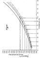
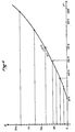
- Figures 4 and 5 illustrate the law of variation of the response temperature of the device of Figures 2 and 3 as a function of the temperature and the pressure of the liquid.
- FIG. 4 represents, as a function of the temperature, different curves of vapor pressure (absolute pressures) of the coolant, consisting of water and of different proportions of ethylene glycol, generally required by the engine manufacturers as explained above, the alarm threshold being located a few degrees below the boiling temperature.
- the coolant corresponding to the curve made of dashes at a boiling temperature of 124 ° C corresponds to an absolute vapor pressure of 1, 9 bar, i.e. a relative pressure of 0.9 bar. If you want to obtain an alarm pressure located at 4 ° C below this value, there must be an alert at 120 ° C for this relative pressure of 0.9 bar.
- a displacement curve D of the piston 2 is thus determined as a function of the temperature (FIG. 5), which then makes it possible to determine the composition of the wax 9.
- the warning temperature for a determined pressure of the liquid cooling, can be adjusted by local depression of the side wall of the housing 8, as shown at 36 in Figures 2 and 3.
Landscapes
- Physics & Mathematics (AREA)
- Thermal Sciences (AREA)
- Fluid Mechanics (AREA)
- Thermally Actuated Switches (AREA)
- Switches Operated By Changes In Physical Conditions (AREA)
- Measuring Fluid Pressure (AREA)
Claims (5)
Applications Claiming Priority (2)
| Application Number | Priority Date | Filing Date | Title |
|---|---|---|---|
| FR8511769A FR2585768B1 (fr) | 1985-08-01 | 1985-08-01 | Dispositif sensible a la fois a la temperature et a la pression, applicable notamment a l'alerte ou a la securite dans les circuits de refroidissement scelles |
| FR8511769 | 1985-08-01 |
Publications (2)
| Publication Number | Publication Date |
|---|---|
| EP0217681A1 EP0217681A1 (de) | 1987-04-08 |
| EP0217681B1 true EP0217681B1 (de) | 1990-10-10 |
Family
ID=9321858
Family Applications (1)
| Application Number | Title | Priority Date | Filing Date |
|---|---|---|---|
| EP19860401565 Expired - Lifetime EP0217681B1 (de) | 1985-08-01 | 1986-07-15 | Temperatur- und druckempfindliche Vorrichtung, insbesondere zur Anwendung bei der Warnung und der Sicherung in Kühlungskreisen |
Country Status (3)
| Country | Link |
|---|---|
| EP (1) | EP0217681B1 (de) |
| DE (1) | DE3674876D1 (de) |
| FR (1) | FR2585768B1 (de) |
Families Citing this family (1)
| Publication number | Priority date | Publication date | Assignee | Title |
|---|---|---|---|---|
| FR2618940B1 (fr) * | 1987-07-28 | 1995-06-02 | Vernet Procedes Sa | Perfectionnements aux thermocontacts a disque cloquant |
Family Cites Families (6)
| Publication number | Priority date | Publication date | Assignee | Title |
|---|---|---|---|---|
| US3129309A (en) * | 1960-04-12 | 1964-04-14 | Westinghouse Canada Ltd | Temperature-compensated pressure switches for controlling gas blast circuit interrupters |
| US3161740A (en) * | 1962-06-06 | 1964-12-15 | Gen Motors Corp | Boiling point anticipator for effecting warning signal |
| FR2449328A1 (fr) * | 1979-02-16 | 1980-09-12 | Peugeot | Thermocontact sensible a la pression |
| FR2486238A1 (fr) * | 1980-07-02 | 1982-01-08 | Calorstat Investissements | Perfectionnements aux dispositifs de contacts electriques sensibles a la temperature |
| FR2488039A1 (fr) * | 1980-07-29 | 1982-02-05 | Calorstat Investissements | Thermocontact perfectionne notamment pour circuit de refroidissement d'automobiles |
| DE8312296U1 (de) * | 1983-04-27 | 1983-12-01 | Ranco Inc., 43017 Dublin, Ohio | Temperaturabhängig schaltender Schalter |
-
1985
- 1985-08-01 FR FR8511769A patent/FR2585768B1/fr not_active Expired
-
1986
- 1986-07-15 DE DE8686401565T patent/DE3674876D1/de not_active Expired - Fee Related
- 1986-07-15 EP EP19860401565 patent/EP0217681B1/de not_active Expired - Lifetime
Also Published As
| Publication number | Publication date |
|---|---|
| FR2585768A1 (fr) | 1987-02-06 |
| EP0217681A1 (de) | 1987-04-08 |
| DE3674876D1 (de) | 1990-11-15 |
| FR2585768B1 (fr) | 1989-07-07 |
Similar Documents
| Publication | Publication Date | Title |
|---|---|---|
| CA1256961A (fr) | Pressostat compense en temperature extincteur a securite de fonctionement equipe d'un tel pressostat et procede de remplissage d'un tel pressostat | |
| WO2010029224A1 (fr) | Detecteur de surpression et de talonnage pour amortisseur ou similaire | |
| FR2492886A1 (fr) | Appareil de commande detecteur d'altitude | |
| EP2705296A1 (de) | An einen hochdruckgastank montiertes ventil | |
| EP0217681A1 (de) | Temperatur- und druckempfindliche Vorrichtung, insbesondere zur Anwendung bei der Warnung und der Sicherung in Kühlungskreisen | |
| EP0556095A1 (de) | Thermostatisches Sicherheitsventil für einen hydraulischen Kühlkreis | |
| FR2644550A1 (fr) | Ensemble combine de regulateur de pression d'huile et d'indicateur de basse pression d'huile pour un compresseur de fluide refrigerant | |
| EP0128096A1 (de) | Antrieb mit pneumatischem Druckspeicher, insbesondere für Ventile | |
| EP0226476B1 (de) | Spannungsmessschaltung für eine abgeschirmte Hochspannungseinrichtung | |
| FR2936715A1 (fr) | Dispositif d'ejection d'un fluide a etancheite renforcee | |
| EP0000680B1 (de) | Standanzeiger für eine in einem Behälter erhaltene Flüssigkeit | |
| FR2539435A3 (fr) | Dispositif a soupape de securite utilisable plus particulierement sur les chaudieres de production de vapeur pour des appareils a usage domestique | |
| FR2697582A1 (fr) | Dispositif de détection de carburant dans un réservoir à huile d'un turboréacteur. | |
| EP0302770B1 (de) | Thermokontakte mit Schnappscheibe | |
| EP1115990A1 (de) | Sicherheitsventil für einen druckbehälter , inbesondere einem tank für flüssiges propangas | |
| FR2774062A1 (fr) | Detendeur de plongee sous-marine, qualifie en eau froide | |
| FR2707424A3 (fr) | Thermostat à tige pour chauffe-eau à double action de sûreté et basse inertie thermique d'intervention. | |
| FR2521769A1 (fr) | Contacteur thermostatique sensible a la pression | |
| EP0631079A1 (de) | Bistabiles Steuerventil und seine Verwendung zum Betätigen eines Ventils oder eines Ablaseschiebers | |
| FR2722833A1 (fr) | Circuit de refroidissement de moteur a remplissage rapide | |
| FR2488039A1 (fr) | Thermocontact perfectionne notamment pour circuit de refroidissement d'automobiles | |
| GB2124030A (en) | Thermostatic switch | |
| WO1991012511A1 (fr) | Installation de controle de la compression d'un moteur a combustion interne | |
| FR2750246A1 (fr) | Procede de surveillance d'un disjoncteur haute tension a circuit hydraulique de commande | |
| FR2689235A1 (fr) | Dispositif de mesure différentielle de la pression d'un gaz confiné dans une enceinte et procédé de mise en Óoeuvre d'un tel dispositif dans un disjoncteur. |
Legal Events
| Date | Code | Title | Description |
|---|---|---|---|
| PUAI | Public reference made under article 153(3) epc to a published international application that has entered the european phase |
Free format text: ORIGINAL CODE: 0009012 |
|
| AK | Designated contracting states |
Kind code of ref document: A1 Designated state(s): DE GB IT |
|
| 17P | Request for examination filed |
Effective date: 19870930 |
|
| 17Q | First examination report despatched |
Effective date: 19900205 |
|
| GRAA | (expected) grant |
Free format text: ORIGINAL CODE: 0009210 |
|
| AK | Designated contracting states |
Kind code of ref document: B1 Designated state(s): DE GB IT |
|
| ITF | It: translation for a ep patent filed | ||
| REF | Corresponds to: |
Ref document number: 3674876 Country of ref document: DE Date of ref document: 19901115 |
|
| GBT | Gb: translation of ep patent filed (gb section 77(6)(a)/1977) | ||
| ITTA | It: last paid annual fee | ||
| PLBE | No opposition filed within time limit |
Free format text: ORIGINAL CODE: 0009261 |
|
| STAA | Information on the status of an ep patent application or granted ep patent |
Free format text: STATUS: NO OPPOSITION FILED WITHIN TIME LIMIT |
|
| 26N | No opposition filed | ||
| PGFP | Annual fee paid to national office [announced via postgrant information from national office to epo] |
Ref country code: GB Payment date: 19920618 Year of fee payment: 7 |
|
| PGFP | Annual fee paid to national office [announced via postgrant information from national office to epo] |
Ref country code: DE Payment date: 19920706 Year of fee payment: 7 |
|
| PG25 | Lapsed in a contracting state [announced via postgrant information from national office to epo] |
Ref country code: GB Effective date: 19930715 |
|
| GBPC | Gb: european patent ceased through non-payment of renewal fee |
Effective date: 19930715 |
|
| PG25 | Lapsed in a contracting state [announced via postgrant information from national office to epo] |
Ref country code: DE Effective date: 19940401 |
|
| PG25 | Lapsed in a contracting state [announced via postgrant information from national office to epo] |
Ref country code: IT Free format text: LAPSE BECAUSE OF NON-PAYMENT OF DUE FEES;WARNING: LAPSES OF ITALIAN PATENTS WITH EFFECTIVE DATE BEFORE 2007 MAY HAVE OCCURRED AT ANY TIME BEFORE 2007. THE CORRECT EFFECTIVE DATE MAY BE DIFFERENT FROM THE ONE RECORDED. Effective date: 20050715 |