EP0217738A1 - Ablassventilvorrichtung für sanitäre Einrichtung - Google Patents
Ablassventilvorrichtung für sanitäre Einrichtung Download PDFInfo
- Publication number
- EP0217738A1 EP0217738A1 EP19860810100 EP86810100A EP0217738A1 EP 0217738 A1 EP0217738 A1 EP 0217738A1 EP 19860810100 EP19860810100 EP 19860810100 EP 86810100 A EP86810100 A EP 86810100A EP 0217738 A1 EP0217738 A1 EP 0217738A1
- Authority
- EP
- European Patent Office
- Prior art keywords
- valve
- fixed member
- radial element
- evacuation device
- open position
- Prior art date
- Legal status (The legal status is an assumption and is not a legal conclusion. Google has not performed a legal analysis and makes no representation as to the accuracy of the status listed.)
- Withdrawn
Links
Images

Classifications
-
- E—FIXED CONSTRUCTIONS
- E03—WATER SUPPLY; SEWERAGE
- E03C—DOMESTIC PLUMBING INSTALLATIONS FOR FRESH WATER OR WASTE WATER; SINKS
- E03C1/00—Domestic plumbing installations for fresh water or waste water; Sinks
- E03C1/12—Plumbing installations for waste water; Basins or fountains connected thereto; Sinks
- E03C1/22—Outlet devices mounted in basins, baths, or sinks
- E03C1/23—Outlet devices mounted in basins, baths, or sinks with mechanical closure mechanisms
- E03C1/2306—Outlet devices mounted in basins, baths, or sinks with mechanical closure mechanisms the plug being operated by hand contact
-
- E—FIXED CONSTRUCTIONS
- E03—WATER SUPPLY; SEWERAGE
- E03C—DOMESTIC PLUMBING INSTALLATIONS FOR FRESH WATER OR WASTE WATER; SINKS
- E03C1/00—Domestic plumbing installations for fresh water or waste water; Sinks
- E03C1/12—Plumbing installations for waste water; Basins or fountains connected thereto; Sinks
- E03C1/22—Outlet devices mounted in basins, baths, or sinks
- E03C1/23—Outlet devices mounted in basins, baths, or sinks with mechanical closure mechanisms
Definitions
- valve discharge devices used in sanitary appliances such as baths, sinks and bidets.
- the simplest consists of a stopper which is placed by hand and which is connected to the container by a chain.
- This system is not hygienic, bacteria can attach to the chain; moreover, it is unsightly in the open position; an involuntary pull on the chain causes the unexpected flow.
- valve devices are actuated by a linkage connected to a control placed either on the sanitary appliance, close to the valve or combined with it, or even laterally next to the container. They have the drawback of complex and costly manufacturing and of difficult assembly. In addition, they tend to out of balance with use and therefore require maintenance. We have also thought of using the principle of the screw or that of helical cams whose applications are common in mechanics, for example to obtain the back and forth of a part by its support on helical bearings in rotation and vice versa.
- the present invention overcomes the above drawbacks by providing a direct control device, of a simple construction and in accordance with claim 1, and where the instantaneous extraction of the valve leaves the plug free of any obstacle.
- the plug 22 is threaded and fixed to the sanitary appliance 20 by means of a tightening nut 23 compressing a seal 24 against the part 20 of this appliance.
- the interior of the lower part of the plug 22 constitutes a fixed member, of generally annular cylindrical shape, the upper surface of which forms three identical cams 25 which can also be seen in the form developed in FIG. 7.
- Each cam 25, of which the guide surface is inclined (for example at 45 °) relative to the axis and in the direction of flow, therefore towards the inside of the bung 22, in order to avoid any retention of solid material, has a lower part 26, a cam track 27, and an upper part 28.
- the slope of this upper part 28 seen from the front is zero, or even slightly reversed.
- Three stops 29 acting on two of their faces are arranged between the cams 25 ( Figure 2).
- the upper surface of the stops 29 is inclined inwards in the same way as the cam surfaces 26, 27, 28.
- the valve 30 rests on a fixed seat 31.
- the contact is ensured by an annular seal 32.
- the vertical rod 33 of the valve is formed by the junction of three radial elements 34 of which at least part 35 is formed of a self-lubricating material and resistant to wear and the oblique lower part of which slides on the cams described above. In the position represented by FIG. 1, contact is not established between the cams 25 and the radial elements 34 and it is the head 30 of the valve which rests on its seat 31.
- the three radial elements 34 guarantee, by sliding with play in the threaded plug 22, the vertical retention of the valve in any position, while promoting the flow of water.
- the degree of opening of the valve is preset by the level of the surface 28 and by the length of the radial elements 34, so as to prevent the passage of objects such as rings, toothpaste plugs or the like.
- the angular position of the rib 36 indicates whether the valve is closed or open.
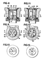
- the cams 25 are replaced by bearing surfaces 45 and stops 46 corresponding to the stops 29.
- the bearing surfaces 45 are at constant level but inclined inwards, like the cam surfaces 26, 27 , 28 of the first embodiment.
- the upper surface of the stops 46 is inclined in the same way.
- Each bearing surface 45 ends at one end with a stop 46 and at its opposite end with an interruption 52.
- the valve 47 has a rod forming three radial elements 48, a seal 49 cooperating with a seat 50, and a gripping and actuating rib 51.
- the elements 48 have parts 53 similar to the parts 35, designed to cooperate with conical bearing surfaces 45 d ' a piece 44 similar to 25.
- this second embodiment is as follows. In the position of the organs according to fig. 8, 9 and 10, the elements 48 are in the interruptions or voids 52 and the valve rests closed on its seat 50. If the rib 51 is grasped, lift the valve 47 to release the elements 48 from the voids 52 and that it is rotated in the direction of the arrows in fig. 10, these elements are brought to abut against the stops 46. Then the rib 51 is released, the parts 53 come to rest on the bearing surfaces 45 (if they had been raised above). Therefore, the valve is and remains open. We are then in the position illustrated by FIGS. 11 to 13. To close the valve, simply rotate it in the direction of the arrows in fig. 13, until the elements 48 arrive against the stops 46 and fall into the interruptions or voids 52 and we find our in the position according to FIG. 8 to 10. Thus the opening and closing are done without trial and error.
Landscapes
- Engineering & Computer Science (AREA)
- Mechanical Engineering (AREA)
- Environmental & Geological Engineering (AREA)
- Health & Medical Sciences (AREA)
- Life Sciences & Earth Sciences (AREA)
- Hydrology & Water Resources (AREA)
- Public Health (AREA)
- Water Supply & Treatment (AREA)
- Mechanically-Actuated Valves (AREA)
- Sink And Installation For Waste Water (AREA)
Applications Claiming Priority (2)
| Application Number | Priority Date | Filing Date | Title |
|---|---|---|---|
| CH255485 | 1985-06-17 | ||
| CH2554/85 | 1985-06-17 |
Publications (1)
| Publication Number | Publication Date |
|---|---|
| EP0217738A1 true EP0217738A1 (de) | 1987-04-08 |
Family
ID=4236409
Family Applications (1)
| Application Number | Title | Priority Date | Filing Date |
|---|---|---|---|
| EP19860810100 Withdrawn EP0217738A1 (de) | 1985-06-17 | 1986-02-26 | Ablassventilvorrichtung für sanitäre Einrichtung |
Country Status (4)
| Country | Link |
|---|---|
| EP (1) | EP0217738A1 (de) |
| DE (1) | DE8606855U1 (de) |
| ES (1) | ES8703174A1 (de) |
| PT (1) | PT82567A (de) |
Families Citing this family (1)
| Publication number | Priority date | Publication date | Assignee | Title |
|---|---|---|---|---|
| WO1998054416A1 (en) * | 1997-05-27 | 1998-12-03 | Senova Ab | A floor drain |
Citations (6)
| Publication number | Priority date | Publication date | Assignee | Title |
|---|---|---|---|---|
| US1613251A (en) * | 1925-07-16 | 1927-01-04 | Lewis H Stead | Plumbing fixture |
| DE2722585A1 (de) * | 1976-05-27 | 1977-12-08 | Emco Ltd | Verschluss fuer den abflusstutzen einer badewanne, eines waschbeckens o.dgl. |
| US4143432A (en) * | 1976-05-21 | 1979-03-13 | Deken Frederick J | Adjustable drain plug |
| US4320540A (en) * | 1980-07-24 | 1982-03-23 | Waltec, Inc. | Discharge drain assembly |
| FR2528090A1 (fr) * | 1982-06-03 | 1983-12-09 | Fonderie Soc Gen De | Dispositif de vidage pour un appareil sanitaire |
| DE3320124A1 (de) * | 1983-06-03 | 1984-12-13 | Hans Grohe Gmbh & Co Kg, 7622 Schiltach | Sanitaeres ablaufventil |
-
1986
- 1986-02-26 EP EP19860810100 patent/EP0217738A1/de not_active Withdrawn
- 1986-03-12 DE DE19868606855 patent/DE8606855U1/de not_active Expired
- 1986-05-12 PT PT8256786A patent/PT82567A/pt not_active Application Discontinuation
- 1986-05-22 ES ES555207A patent/ES8703174A1/es not_active Expired
Patent Citations (6)
| Publication number | Priority date | Publication date | Assignee | Title |
|---|---|---|---|---|
| US1613251A (en) * | 1925-07-16 | 1927-01-04 | Lewis H Stead | Plumbing fixture |
| US4143432A (en) * | 1976-05-21 | 1979-03-13 | Deken Frederick J | Adjustable drain plug |
| DE2722585A1 (de) * | 1976-05-27 | 1977-12-08 | Emco Ltd | Verschluss fuer den abflusstutzen einer badewanne, eines waschbeckens o.dgl. |
| US4320540A (en) * | 1980-07-24 | 1982-03-23 | Waltec, Inc. | Discharge drain assembly |
| FR2528090A1 (fr) * | 1982-06-03 | 1983-12-09 | Fonderie Soc Gen De | Dispositif de vidage pour un appareil sanitaire |
| DE3320124A1 (de) * | 1983-06-03 | 1984-12-13 | Hans Grohe Gmbh & Co Kg, 7622 Schiltach | Sanitaeres ablaufventil |
Also Published As
| Publication number | Publication date |
|---|---|
| ES555207A0 (es) | 1987-02-16 |
| ES8703174A1 (es) | 1987-02-16 |
| DE8606855U1 (de) | 1986-05-15 |
| PT82567A (fr) | 1986-06-01 |
Similar Documents
| Publication | Publication Date | Title |
|---|---|---|
| FR2936000A1 (fr) | Dispositif de chasse d'eau notamment pour cuvette de w.c. et ensemble de cuvette de w.c. et dispositif de chasse d'eau obtenu | |
| FR2704525A1 (fr) | Ensemble de verrouillage de bouchon. | |
| EP0217738A1 (de) | Ablassventilvorrichtung für sanitäre Einrichtung | |
| FR2668890A1 (fr) | Abreuvoir pour le betail. | |
| EP0124458A1 (de) | Spülvorrichtung für einen Spülkasten zu Betätigen durch einen Druckknopf | |
| FR2606296A1 (fr) | Rampe de pulverisation d'un fluide | |
| WO1997017503A1 (fr) | Dispositif a double commande de chasse de reservoir d'eau | |
| EP0209477B1 (de) | Spülvorrichtung mit schwimmender Heberglocke für Spülkasten | |
| EP0209478B1 (de) | Unantastbare Druckknopfvorrichtung zum Bedienen eines Spülmechanismus eines Spültasters | |
| CH557493A (fr) | Soupape de vidange pour canalisation d'eaux usees. | |
| WO1995017558A1 (fr) | Dispositif de chasse d'eau a guidage central pour reservoir de sanitaires | |
| EP0128847B1 (de) | Mechanismus zum Umkehren von Bewegungen und seine Anwendung für Dränagevorrichtungen für Spülbecken | |
| FR2665744A1 (fr) | Clapet pour la commande de l'ecoulement d'un liquide a partir d'un reservoir. | |
| FR2804143A1 (fr) | Dispositif de garnissage pour couvercle de reservoir de chasse d'eau et reservoir de chasse d'eau correspondant | |
| FR2494464A1 (fr) | Dispositif pour le remplissage d'un reservoir de chasse d'eau | |
| FR2682140A1 (fr) | Dispositif controlant le volume d'eau libere par une chasse d'eau. | |
| FR2699203A1 (fr) | Perfectionnements apportés aux déchargeurs de citernes pour cabinets d'aisance. | |
| FR2724291A1 (fr) | Pipette d'abreuvement pour des animaux rongeurs | |
| FR2724306A1 (fr) | Urinoir independant et solidaire des cuvettes de toilette | |
| FR2508954A1 (fr) | Dispositif de commande de bonde | |
| FR2594866A1 (fr) | Dispositif economiseur d'eau pour reservoir a deux capacites d'ecoulement | |
| FR2653797A1 (fr) | Dispositif d'actionnement controle pour clapet de chasse-d'eau. | |
| FR3166516A1 (fr) | Dispositif de vidange pour réservoir de liquide | |
| FR2842226A1 (fr) | Dispositif de fermeture automatique des robinets utilises pour le remplissage de reservoirs | |
| FR2907874A1 (fr) | Economiseur d'eau a commande a impulsion manuelle adaptable sur le bec d'un robinet |
Legal Events
| Date | Code | Title | Description |
|---|---|---|---|
| PUAI | Public reference made under article 153(3) epc to a published international application that has entered the european phase |
Free format text: ORIGINAL CODE: 0009012 |
|
| AK | Designated contracting states |
Kind code of ref document: A1 Designated state(s): AT CH DE FR GB IT LI NL SE |
|
| 17P | Request for examination filed |
Effective date: 19870706 |
|
| 17Q | First examination report despatched |
Effective date: 19880823 |
|
| STAA | Information on the status of an ep patent application or granted ep patent |
Free format text: STATUS: THE APPLICATION IS DEEMED TO BE WITHDRAWN |
|
| 18D | Application deemed to be withdrawn |
Effective date: 19891219 |
|
| RIN1 | Information on inventor provided before grant (corrected) |
Inventor name: OBERSON, ANDRE |