EP0217758A2 - Procédé et dispositif pour la détection de fissures de production en des pièces mécaniques à cause du travail de pressage - Google Patents
Procédé et dispositif pour la détection de fissures de production en des pièces mécaniques à cause du travail de pressage Download PDFInfo
- Publication number
- EP0217758A2 EP0217758A2 EP86830252A EP86830252A EP0217758A2 EP 0217758 A2 EP0217758 A2 EP 0217758A2 EP 86830252 A EP86830252 A EP 86830252A EP 86830252 A EP86830252 A EP 86830252A EP 0217758 A2 EP0217758 A2 EP 0217758A2
- Authority
- EP
- European Patent Office
- Prior art keywords
- air
- ultrasounds
- pressing
- die
- punch
- Prior art date
- Legal status (The legal status is an assumption and is not a legal conclusion. Google has not performed a legal analysis and makes no representation as to the accuracy of the status listed.)
- Granted
Links
Images

Classifications
-
- G—PHYSICS
- G01—MEASURING; TESTING
- G01N—INVESTIGATING OR ANALYSING MATERIALS BY DETERMINING THEIR CHEMICAL OR PHYSICAL PROPERTIES
- G01N29/00—Investigating or analysing materials by the use of ultrasonic, sonic or infrasonic waves; Visualisation of the interior of objects by transmitting ultrasonic or sonic waves through the object
- G01N29/22—Details, e.g. general constructional or apparatus details
- G01N29/227—Details, e.g. general constructional or apparatus details related to high pressure, tension or stress conditions
-
- G—PHYSICS
- G01—MEASURING; TESTING
- G01N—INVESTIGATING OR ANALYSING MATERIALS BY DETERMINING THEIR CHEMICAL OR PHYSICAL PROPERTIES
- G01N29/00—Investigating or analysing materials by the use of ultrasonic, sonic or infrasonic waves; Visualisation of the interior of objects by transmitting ultrasonic or sonic waves through the object
- G01N29/14—Investigating or analysing materials by the use of ultrasonic, sonic or infrasonic waves; Visualisation of the interior of objects by transmitting ultrasonic or sonic waves through the object using acoustic emission techniques
-
- G—PHYSICS
- G01—MEASURING; TESTING
- G01N—INVESTIGATING OR ANALYSING MATERIALS BY DETERMINING THEIR CHEMICAL OR PHYSICAL PROPERTIES
- G01N2291/00—Indexing codes associated with group G01N29/00
- G01N2291/04—Wave modes and trajectories
- G01N2291/048—Transmission, i.e. analysed material between transmitter and receiver
Definitions
- the present invention relates generally to the problems of detecting and indicating the presence of production cracks in mechanical parts (drawn parts) made by pressing between a punch and a die.
- the cracks which occur during the pressing operation are typically localised in the regions of the part subjected to the most intense plastic deformation (drawing).
- the cracks may in fact arise from the effects of stretching or contraction of the metal constituting the part.
- stretching or contraction usually arises when the interaction of the punch with the die becomes too tight, at least in some regions of the part, due to wear or slight relative displacement during the working cycle.
- the production cracks most usually take the form of tears or fissures which are detectable by visual examination. In other cases, however, the cracks are not immediately perceptible and their presence may be detected only after assembly of the part or, indeed, only by the user of the final product after a certain period of use.
- the object of the present invention is thus to enable the presence of production cracks in mechanical parts obtained by pressing to be detected in accordance with criteria which enable the detection operation to be carried out "in process", that is, during the pressing operation.
- the solution of the invention must enable the checking to be carried out in an easily automated manner with results having a degree of reliability such as to minimise the incidence of such cracks not only in percentage terms but also in absolute terms.
- the object defined above is achieved by virtue of a method for detecting the presence of production cracks in predetermined regions of mechanical parts made by pressing between a punch and a die, characterised in that it includes the step of detecting the presence of ultrasounds in air in the predetermined regions during pressing, this presence of ultrasounds in air being indicative of the existence of production cracks in the pressed part.
- the method of the invention includes the step of generating, during pressing, ultrasounds in air in the predetermined regions and on the side of the part being pressed which faces one of the punch and the die, and the step of detecting the presence of ultrasounds in air in the predetermined regions and on the side of the part being pressed which faces the other of the punch and the die.
- the propagation of ultrasounds in air through the mechanical part being pressed is detected - this being indicative of the presence of production cracks.
- the method of the invention includes the step of supplying pressurised air to the surface of the predetermined regions of the part being pressed during pressing.
- the present invention also provides apparatus which enables the presence of production cracks to be detected in predetermined regions of mechanical parts made by pressing, in accordance with the method described above.
- production cracks is intended to indicate all those anomalies such as tears, fissures, cracks, etc., which may occur in a part manufactured by pressing as a consequence of the deformation (drawing) to which the part, usually of metal, is subject;
- punch and die generally indicates the two bodies with complementary shapes (also termed die and matrix, etc.) which plastically deform the part in order to give the part itself the final conformation by means of an operation generally termed “pressing”;
- the term “during the pressing operation (or cycle)” or, more briefly, “during pressing” indicates those operations carried out during the pressing steps in which there is relative movement between the punch and the die (as defined above) and in the immediately subsequent steps in which the pressed part is still between the punch and the die;
- the term “ultrasounds in air” is intended to indicate generally all those vibrations or ranges of wave forces which are propagated
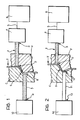
- a region of a mechanical part of metal for example, sheet metal of the FePO4 type subjected to pressing between a punch or die P and a die or matrix C is generally indicated S.
- the part T may constitute the so-called framework of the door of the motor vehicle, while the region S constitutes one of the parts of this framework.
- region S under examination is one of the regions in which the plastic deformation or drawing characteristic of the pressing operation is most marked.
- the ducts or guides l are of known type and are readily available on the market. For this purpose, reference may be made to the plastics guides or ducts tested positively for ultrasonic transmissions and known under the trade name "RINSAL".
- the duct l has a first end 2 which extends through the punch P so as to face the surface of the part T being produced.
- the guide 2 terminates at an ultrasound detector 4, the detector 4 being sensitive to the intensity of the train of ultrasonic pressure waves propagated within the guide l and generating at its output 5 an electrical signal which changes correspondingly.
- the ultrasound detector 4 operates in a range of frequencies of around 40kHz.
- the output 5 of the detector 4 is connected to a signal processing circuit 6 the structure of which will be better explained below with reference to Figure 5.
- a further duct or guide, structurally identical to the duct l, is indicated 7 in Figure l and can enable and guide the propagation of ultrasounds in air within it.
- the duct or guide 7 also has an end 8 which extends through the die C in such a position that, during the pressing operation, the end 8 is in fact applied to the surface of the part T.
- the opposite end of the duct 7, indicated 9, terminates at an ultrasound generator l0 which can release into the guide or duct 7 an ultrasonic signal within a frequency range of around 40kHz, corresponding to the maximum sensitivity range of the detector 4.
- ducts or guides l and 7 may be very short depending upon the manner in which the connection is made adjacent the part subjected to "in process” checking.
- Figure 2 shows a tubular duct, generally indicated ll, having respective ends l2 and l3.
- the end l2 of the duct ll extends through the die C in a configuration entirely similar to that of the end 8 of the duct 7 of Figure l.
- the other end l3 terminates at a pressurised air supply l4.
- the duct ll may be constituted by an ultrasound guide entirely similar to the guide 7 of Figure l.
- the function of the duct ll is different in that this duct is intended solely to convey the pressurised air generated by the source l4 towards the surface of the part T gripped between the punch P and the die C.
- the air may be at a pressure of between l and 6 atmospheres, the value considered preferable at present being about 2 to 3 atmospheres.
- the method of the invention is based on the observation that the propagation of the ultrasounds in air conveyed by the guide 7 to the guide l takes place solely in the production cracks in the region S, that is to say, only when there are tears, fissures or cracks in the region 6. In fact, the latter contain air which constitutes a propagation medium for the ultrasounds.
- the detection of the presence of production cracks in the part T may be carried out "in process", that is, during the pressing operation, the ultrasound generator l0 being activated and it being observed by means of the detector 4 whether the ultrasounds in air produced by the generator l0 are propagated not only through the guide 7 but also through the region S of the part and the guide l.
- the propagation through the region S and the guide l takes place only if there are production cracks; the picking up of ultrasounds in air by the detector 4 is thus indicative of the presence of production cracks.
- the source l4 is activated so as to direct pressurised air through the guide or duct ll towards the part T.
- the part T so to speak "stops" the guide ll and acts as a shield against the ultrasounds produced by the smaller flow of air from the end l2, which are not able to propagate through the part T since it is flawless.
- the pressurised air penetrates these cracks and enables the ultrasounds generated to be propagated both in correspondence with the end l2 and due to the interaction with the walls of these cracks.
- These ultrasounds in air are mainly in the frequency range around 40kHz and propagate in the guide l until they reach the detector 4. Again in this case, the detection of ultrasounds in air in correspondence with the region S is thus indicative of the presence of production cracks in this region.
- the embodiment illustrated in Figure l is more advantageous in terms of sensitivity of detection.
- the experiments carried out by the inventors have in fact shown that with this solution it is possible reliably to detect production cracks with an overall length of less than a centimetre and a width of less than 0.5 mm.
- the solution schematically illustrated in Figure 2 has limits with regard to the sensitivity of detection, mainly due to the distribution of frequencies of the ultrasounds around the frequency of 40kHz.
- this embodiment it is more difficult to identify production cracks with overall lengths of less than l centimetre. It can be installed more easily, however, particularly with regard to the possibility of the use of simple tubes or ducts on the transmission side (that is, on the side of the die C in the embodiment illustrated in Figure 2) for conveying pressurised air and no guides for the ultrasounds, which, as is known, attenuate the ultrasounds themselves.
- the practicality of the ducts for the pressurised air is not seriously affected by the possible infiltration into the ducts themselves of oil or powder which may be present in the industrial environment in which the pressing is carried out.
- such infiltration can seriously compromise the operating characteristics of ultrasound propagation guides.
- Figures 3 and 4 are two graphs in which the scale on the abscissa relates to the time coordinate and the scale on the ordinate relates to the changes in the signal (5';5") at the output 5 of the detector 4.
- Figure 3 the changes in the signal are illustrated in Figure 3 with reference to changes detectable during a pressing operation in which no production cracks are made.
- Figure 4 relates to changes in the signal detectable when the pressing operation causes such cracks to form.
- a square-wave synchronising signal S C is shown in chain line, its course being indicative of the prosecution of the pressing operation. More particularly, the change in the synchronising signal S C to a high logic level is indicative of the moment at which the drawing process is started, that is, the moment at which the punch P starts to act on the part T. The ascending front and the descending front of the signal S C are thus respectively indicative of the start and finish of the pressing operation proper.
- the detector 4 always picks up ultrasounds during the pressing operation, these being due essentially to the general noise of the pressing apparatus in which mechanical parts knock and slide against one another.
- FIG. 5 illustrates in block schematic form the internal structure of the processing circuit 6 to which the signal at the output 5 of the detector 4 is supplied.
- an electrical supply unit indicated l5
- the unit l5 may be used to advantage to supply the ultrasound generator l0.
- the input circuit which amplifies and rectifies (after any conversion to low frequency) the signal present at the output of the detector 4 is indicated l6.
- the output of the input circuit l6 is connected to a first threshold circuit for blocking and interrupting the propagation of signals whose amplitude is less than the predetermined threshold towards the other parts of the device 6.
- the circuit l7 is intended essentially to annul any disturbances or background noises which reach and/or are generated in the detector 4 and in the circuits associated therewith.
- a counter circuit indicated l8, counts the number of half waves or the alternations in the (rectified) signals which pass through the first threshold circuit l7.
- the counter circuit l8 has an enabling input l8a at which a signal generated by a sensor l9 mounted on the pressing device (press) is present.
- the sensor l9 is able to detect the relative movement of the punch P and the die C.
- the sensor l9 generates a signal approximately corresponding to the synchronising signal S C illustrated in Figure 3, enabling the counter l8 to operate only during the pressing operation.
- the sensor l9 therefore has the task of making the counter l8 function only when necessary.
- the sensor l9 may be formed so as to enable the counter l8 only for a selectively predetermined fraction (such as, for example, one of the time windows W1 or W2) of the interval ⁇ in which the pressing is carried out.
- the output signal of the sensor l9 is also directed to the counting input of a further counter 20 which totals the number of pressing operations carried out successfully by the press on which the detection device of the invention is mounted.
- the counting signal emitted by the counter l8 is fed to the input of a further threshold circuit 2l.
- the count value of the counter l8 is compared with a reference count defining the level of discrimination between the parts to be considered good, that is, without production cracks, and the parts wasted, that is, parts with cracks.
- the threshold level of the circuit 2l may be adjusted experimentally in dependence on the characteristics of the parts T and the pressing apparatus.
- parts for which the count of the counter l8 is less than the threshold of the comparator circuit 2l are considered good.
- the parts for which the count of the counter l8 surpasses the threshold are waste due to the presence of production cracks.
- a warning device such as an acoustic or optical warning device 22 activated by the comparator circuit 2l when the threshold is surpassed.
- the operators may thus remove the defective part from the pressing line or operate the conveying apparatus associated therewith to discharge the part.
- the alarm signal emitted by the circuit 2l may be used to control a selector device which can convey the waste parts from the line.
Landscapes
- Physics & Mathematics (AREA)
- Health & Medical Sciences (AREA)
- Life Sciences & Earth Sciences (AREA)
- Chemical & Material Sciences (AREA)
- Analytical Chemistry (AREA)
- Biochemistry (AREA)
- General Health & Medical Sciences (AREA)
- General Physics & Mathematics (AREA)
- Immunology (AREA)
- Pathology (AREA)
- Acoustics & Sound (AREA)
- Investigating Or Analyzing Materials By The Use Of Ultrasonic Waves (AREA)
Applications Claiming Priority (2)
| Application Number | Priority Date | Filing Date | Title |
|---|---|---|---|
| IT6783385 | 1985-09-30 | ||
| IT67833/85A IT1182581B (it) | 1985-09-30 | 1985-09-30 | Procedimento ed apparecchiatura per rilevare la presenza di rotture di lavorazione in pezzi meccanici ottenuti per stampaggio |
Publications (3)
| Publication Number | Publication Date |
|---|---|
| EP0217758A2 true EP0217758A2 (fr) | 1987-04-08 |
| EP0217758A3 EP0217758A3 (en) | 1987-12-09 |
| EP0217758B1 EP0217758B1 (fr) | 1990-12-27 |
Family
ID=11305641
Family Applications (1)
| Application Number | Title | Priority Date | Filing Date |
|---|---|---|---|
| EP86830252A Expired EP0217758B1 (fr) | 1985-09-30 | 1986-09-12 | Procédé et dispositif pour la détection de fissures de production en des pièces mécaniques à cause du travail de pressage |
Country Status (3)
| Country | Link |
|---|---|
| EP (1) | EP0217758B1 (fr) |
| DE (1) | DE3676615D1 (fr) |
| IT (1) | IT1182581B (fr) |
Cited By (7)
| Publication number | Priority date | Publication date | Assignee | Title |
|---|---|---|---|---|
| DE4107093A1 (de) * | 1990-03-19 | 1991-09-26 | Volkswagen Ag | Verfahren zur risspruefung eines formteils in einer pressvorrichtung |
| EP0709672A1 (fr) * | 1994-10-26 | 1996-05-01 | Siemens Aktiengesellschaft | Procédé et dispositif de contrÔle d'un ressort |
| FR2746918A1 (fr) * | 1996-03-28 | 1997-10-03 | Ngk Insulators Ltd | Procede de controle non destructif d'un isolateur en materiau polymere et dispositif pour la mise en oeuvre de ce procede |
| WO2009074220A1 (fr) * | 2007-12-12 | 2009-06-18 | Dr. Ing. H.C. F. Porsche Aktiengesellschaft | Dispositif et procédé de contrôle de qualité de pièces en tôle |
| CN105592948A (zh) * | 2013-05-20 | 2016-05-18 | 麦格纳国际公司 | 检测边缘裂纹 |
| CN106513483A (zh) * | 2016-12-30 | 2017-03-22 | 重庆高威汽车科技有限公司 | 一种可全方位检测裂缝的钣金冲压装置 |
| CN106623569A (zh) * | 2016-12-30 | 2017-05-10 | 重庆高威汽车科技有限公司 | 一种带加热功能的钣金冲压装置 |
Families Citing this family (2)
| Publication number | Priority date | Publication date | Assignee | Title |
|---|---|---|---|---|
| DE10343002A1 (de) * | 2003-09-17 | 2005-04-14 | Bayerische Motoren Werke Ag | Werkzeug zum Umformen von Blechen oder Kunststofffolien mit Vorwarnung der Rißgefahr bei hoher Materialausdünnung |
| DE10343001A1 (de) * | 2003-09-17 | 2005-04-14 | Bayerische Motoren Werke Ag | Werkzeug zum Umformen von Blechen oder Kunststofffolien mit integriertem Rißalarm |
Family Cites Families (6)
| Publication number | Priority date | Publication date | Assignee | Title |
|---|---|---|---|---|
| DE749940C (de) * | 1942-08-29 | 1945-01-10 | Verfahren zur Werkstoffpruefung mittels Ultraschallwellen | |
| BE521715A (fr) * | 1952-07-25 | |||
| GB1131075A (en) * | 1965-03-31 | 1968-10-23 | Mini Of Technology | Ultrasonic inspection apparatus and method |
| GB1290978A (fr) * | 1970-09-02 | 1972-09-27 | ||
| DE2757355A1 (de) * | 1977-12-22 | 1979-07-05 | Krautkraemer Gmbh | Ultraschallvorrichtung zur zerstoerungsfreien pruefung von bindeflaechen |
| DE3342463A1 (de) * | 1982-11-26 | 1984-05-30 | Basf Ag, 6700 Ludwigshafen | Verfahren zur ueberwachung des fortschreitens von rissen in maschinen- und bauteilen |
-
1985
- 1985-09-30 IT IT67833/85A patent/IT1182581B/it active
-
1986
- 1986-09-12 EP EP86830252A patent/EP0217758B1/fr not_active Expired
- 1986-09-12 DE DE8686830252T patent/DE3676615D1/de not_active Expired - Fee Related
Cited By (9)
| Publication number | Priority date | Publication date | Assignee | Title |
|---|---|---|---|---|
| DE4107093A1 (de) * | 1990-03-19 | 1991-09-26 | Volkswagen Ag | Verfahren zur risspruefung eines formteils in einer pressvorrichtung |
| EP0709672A1 (fr) * | 1994-10-26 | 1996-05-01 | Siemens Aktiengesellschaft | Procédé et dispositif de contrÔle d'un ressort |
| FR2746918A1 (fr) * | 1996-03-28 | 1997-10-03 | Ngk Insulators Ltd | Procede de controle non destructif d'un isolateur en materiau polymere et dispositif pour la mise en oeuvre de ce procede |
| WO2009074220A1 (fr) * | 2007-12-12 | 2009-06-18 | Dr. Ing. H.C. F. Porsche Aktiengesellschaft | Dispositif et procédé de contrôle de qualité de pièces en tôle |
| US8365598B2 (en) | 2007-12-12 | 2013-02-05 | Dr. Ing. H.C. F. Porsche Aktiengesellschaft | Device and method for quality testing sheet metal parts |
| CN105592948A (zh) * | 2013-05-20 | 2016-05-18 | 麦格纳国际公司 | 检测边缘裂纹 |
| CN105592948B (zh) * | 2013-05-20 | 2018-07-13 | 麦格纳国际公司 | 检测边缘裂纹 |
| CN106513483A (zh) * | 2016-12-30 | 2017-03-22 | 重庆高威汽车科技有限公司 | 一种可全方位检测裂缝的钣金冲压装置 |
| CN106623569A (zh) * | 2016-12-30 | 2017-05-10 | 重庆高威汽车科技有限公司 | 一种带加热功能的钣金冲压装置 |
Also Published As
| Publication number | Publication date |
|---|---|
| IT8567833A0 (it) | 1985-09-30 |
| EP0217758A3 (en) | 1987-12-09 |
| EP0217758B1 (fr) | 1990-12-27 |
| IT1182581B (it) | 1987-10-05 |
| DE3676615D1 (de) | 1991-02-07 |
Similar Documents
| Publication | Publication Date | Title |
|---|---|---|
| US4144766A (en) | Apparatus for the in-situ detection and location of flaws in welds | |
| EP0217758B1 (fr) | Procédé et dispositif pour la détection de fissures de production en des pièces mécaniques à cause du travail de pressage | |
| US4429576A (en) | Ultrasonic inspection apparatus | |
| US7984649B2 (en) | Panel inspection apparatus and inspection method | |
| CA1184648A (fr) | Controle non destructif aux ultrasons pour la denture d'un rotor de generatrice | |
| GB2034035A (en) | Ultrasonic testing of weld seams | |
| CN107350167A (zh) | 踢废装置及踢废方法 | |
| CN118090904B (zh) | 一种用于矿物输送皮带纵撕裂缝检测的接头定位方法 | |
| CN102384919B (zh) | 聚乙烯管道热熔接头的微波扫描检测方法和检测装置 | |
| KR20160039916A (ko) | 프레스 판넬의 결함 검출 장치 및 그 방법 | |
| CA2616900A1 (fr) | Procede de verification non destructive de tuyaux, pour detecter d'eventuels defauts superficiels | |
| US5275050A (en) | Process for quality control of products having parts made of elastomeric material | |
| JP4257076B2 (ja) | 管内面付着物の測定方法 | |
| CN118090924B (zh) | 一种输送皮带纵撕裂缝检测方法 | |
| CA2543261A1 (fr) | Procede et appareil de controle d'objets par ultrasons | |
| US4185921A (en) | Surface flaw detector | |
| US3208268A (en) | Detection of almost periodic occurrences | |
| US3512399A (en) | Ultrasonic inspection and fail-safe indication method and apparatus | |
| JP2727132B2 (ja) | 工具に割れ検出部を内蔵したプレス装置 | |
| GB2124379A (en) | Improvements in or relating to ultrasonic testing | |
| EP3543688A1 (fr) | Procédé d'inspection | |
| JP3843642B2 (ja) | 金属板のエッジ検出方法 | |
| CN213238408U (zh) | 一种转底炉的炉底高度检测装置 | |
| CN210894223U (zh) | 一种钢轨焊缝串列式检测装置 | |
| SU1116388A1 (ru) | Устройство дл контрол качества поверхности изделий |
Legal Events
| Date | Code | Title | Description |
|---|---|---|---|
| PUAI | Public reference made under article 153(3) epc to a published international application that has entered the european phase |
Free format text: ORIGINAL CODE: 0009012 |
|
| AK | Designated contracting states |
Kind code of ref document: A2 Designated state(s): DE FR GB SE |
|
| PUAL | Search report despatched |
Free format text: ORIGINAL CODE: 0009013 |
|
| AK | Designated contracting states |
Kind code of ref document: A3 Designated state(s): DE FR GB SE |
|
| 17P | Request for examination filed |
Effective date: 19871204 |
|
| 17Q | First examination report despatched |
Effective date: 19890714 |
|
| GRAA | (expected) grant |
Free format text: ORIGINAL CODE: 0009210 |
|
| AK | Designated contracting states |
Kind code of ref document: B1 Designated state(s): DE FR GB SE |
|
| REF | Corresponds to: |
Ref document number: 3676615 Country of ref document: DE Date of ref document: 19910207 |
|
| ET | Fr: translation filed | ||
| PLBE | No opposition filed within time limit |
Free format text: ORIGINAL CODE: 0009261 |
|
| STAA | Information on the status of an ep patent application or granted ep patent |
Free format text: STATUS: NO OPPOSITION FILED WITHIN TIME LIMIT |
|
| 26N | No opposition filed | ||
| PGFP | Annual fee paid to national office [announced via postgrant information from national office to epo] |
Ref country code: DE Payment date: 19930813 Year of fee payment: 8 |
|
| PGFP | Annual fee paid to national office [announced via postgrant information from national office to epo] |
Ref country code: GB Payment date: 19930816 Year of fee payment: 8 |
|
| PGFP | Annual fee paid to national office [announced via postgrant information from national office to epo] |
Ref country code: SE Payment date: 19930818 Year of fee payment: 8 |
|
| PGFP | Annual fee paid to national office [announced via postgrant information from national office to epo] |
Ref country code: FR Payment date: 19930930 Year of fee payment: 8 |
|
| PG25 | Lapsed in a contracting state [announced via postgrant information from national office to epo] |
Ref country code: GB Effective date: 19940912 |
|
| PG25 | Lapsed in a contracting state [announced via postgrant information from national office to epo] |
Ref country code: SE Effective date: 19940913 |
|
| EAL | Se: european patent in force in sweden |
Ref document number: 86830252.2 |
|
| GBPC | Gb: european patent ceased through non-payment of renewal fee |
Effective date: 19940912 |
|
| PG25 | Lapsed in a contracting state [announced via postgrant information from national office to epo] |
Ref country code: FR Effective date: 19950531 |
|
| PG25 | Lapsed in a contracting state [announced via postgrant information from national office to epo] |
Ref country code: DE Effective date: 19950601 |
|
| EUG | Se: european patent has lapsed |
Ref document number: 86830252.2 |
|
| REG | Reference to a national code |
Ref country code: FR Ref legal event code: ST |