EP0217759B1 - Hohlfaser-Blutoxygenatoren - Google Patents
Hohlfaser-Blutoxygenatoren Download PDFInfo
- Publication number
- EP0217759B1 EP0217759B1 EP86830261A EP86830261A EP0217759B1 EP 0217759 B1 EP0217759 B1 EP 0217759B1 EP 86830261 A EP86830261 A EP 86830261A EP 86830261 A EP86830261 A EP 86830261A EP 0217759 B1 EP0217759 B1 EP 0217759B1
- Authority
- EP
- European Patent Office
- Prior art keywords
- diffuser
- fluid
- fibres
- arms
- oxygenator
- Prior art date
- Legal status (The legal status is an assumption and is not a legal conclusion. Google has not performed a legal analysis and makes no representation as to the accuracy of the status listed.)
- Expired
Links
- 239000008280 blood Substances 0.000 title claims abstract description 25
- 210000004369 blood Anatomy 0.000 title claims abstract description 25
- 239000000835 fiber Substances 0.000 title claims abstract description 10
- 239000012530 fluid Substances 0.000 claims abstract description 21
- QVGXLLKOCUKJST-UHFFFAOYSA-N atomic oxygen Chemical compound [O] QVGXLLKOCUKJST-UHFFFAOYSA-N 0.000 claims description 19
- 229910052760 oxygen Inorganic materials 0.000 claims description 19
- 239000001301 oxygen Substances 0.000 claims description 19
- 239000007789 gas Substances 0.000 claims description 12
- 239000000853 adhesive Substances 0.000 claims description 3
- 230000001070 adhesive effect Effects 0.000 claims description 3
- 239000000203 mixture Substances 0.000 claims description 3
- CURLTUGMZLYLDI-UHFFFAOYSA-N Carbon dioxide Chemical compound O=C=O CURLTUGMZLYLDI-UHFFFAOYSA-N 0.000 description 16
- 229910002092 carbon dioxide Inorganic materials 0.000 description 8
- 239000001569 carbon dioxide Substances 0.000 description 8
- 238000006213 oxygenation reaction Methods 0.000 description 5
- 239000000463 material Substances 0.000 description 4
- 238000000034 method Methods 0.000 description 4
- 238000010586 diagram Methods 0.000 description 2
- 238000009826 distribution Methods 0.000 description 2
- 230000000694 effects Effects 0.000 description 2
- 238000003780 insertion Methods 0.000 description 2
- 230000037431 insertion Effects 0.000 description 2
- 239000007788 liquid Substances 0.000 description 2
- 210000004072 lung Anatomy 0.000 description 2
- 238000000465 moulding Methods 0.000 description 2
- 239000002245 particle Substances 0.000 description 2
- 230000002093 peripheral effect Effects 0.000 description 2
- 239000004033 plastic Substances 0.000 description 2
- 229920003023 plastic Polymers 0.000 description 2
- -1 polypropylene Polymers 0.000 description 2
- 239000004698 Polyethylene Substances 0.000 description 1
- 239000004743 Polypropylene Substances 0.000 description 1
- 239000004840 adhesive resin Substances 0.000 description 1
- 229920006223 adhesive resin Polymers 0.000 description 1
- 230000004075 alteration Effects 0.000 description 1
- 238000003287 bathing Methods 0.000 description 1
- 230000005587 bubbling Effects 0.000 description 1
- 238000007675 cardiac surgery Methods 0.000 description 1
- 230000008859 change Effects 0.000 description 1
- 238000005516 engineering process Methods 0.000 description 1
- 238000004519 manufacturing process Methods 0.000 description 1
- 239000002991 molded plastic Substances 0.000 description 1
- 230000035790 physiological processes and functions Effects 0.000 description 1
- 239000004417 polycarbonate Substances 0.000 description 1
- 229920000515 polycarbonate Polymers 0.000 description 1
- 229920000573 polyethylene Polymers 0.000 description 1
- 229920005672 polyolefin resin Polymers 0.000 description 1
- 229920001155 polypropylene Polymers 0.000 description 1
- 229920002635 polyurethane Polymers 0.000 description 1
- 239000004814 polyurethane Substances 0.000 description 1
- 239000011148 porous material Substances 0.000 description 1
- SCUZVMOVTVSBLE-UHFFFAOYSA-N prop-2-enenitrile;styrene Chemical compound C=CC#N.C=CC1=CC=CC=C1 SCUZVMOVTVSBLE-UHFFFAOYSA-N 0.000 description 1
- 230000009467 reduction Effects 0.000 description 1
- 229920005989 resin Polymers 0.000 description 1
- 239000011347 resin Substances 0.000 description 1
- 229920000638 styrene acrylonitrile Polymers 0.000 description 1
Images


Classifications
-
- A—HUMAN NECESSITIES
- A61—MEDICAL OR VETERINARY SCIENCE; HYGIENE
- A61M—DEVICES FOR INTRODUCING MEDIA INTO, OR ONTO, THE BODY; DEVICES FOR TRANSDUCING BODY MEDIA OR FOR TAKING MEDIA FROM THE BODY; DEVICES FOR PRODUCING OR ENDING SLEEP OR STUPOR
- A61M1/00—Suction or pumping devices for medical purposes; Devices for carrying-off, for treatment of, or for carrying-over, body-liquids; Drainage systems
- A61M1/14—Dialysis systems; Artificial kidneys; Blood oxygenators ; Reciprocating systems for treatment of body fluids, e.g. single needle systems for hemofiltration or pheresis
- A61M1/16—Dialysis systems; Artificial kidneys; Blood oxygenators ; Reciprocating systems for treatment of body fluids, e.g. single needle systems for hemofiltration or pheresis with membranes
- A61M1/1698—Blood oxygenators with or without heat-exchangers
-
- A—HUMAN NECESSITIES
- A61—MEDICAL OR VETERINARY SCIENCE; HYGIENE
- A61M—DEVICES FOR INTRODUCING MEDIA INTO, OR ONTO, THE BODY; DEVICES FOR TRANSDUCING BODY MEDIA OR FOR TAKING MEDIA FROM THE BODY; DEVICES FOR PRODUCING OR ENDING SLEEP OR STUPOR
- A61M1/00—Suction or pumping devices for medical purposes; Devices for carrying-off, for treatment of, or for carrying-over, body-liquids; Drainage systems
- A61M1/14—Dialysis systems; Artificial kidneys; Blood oxygenators ; Reciprocating systems for treatment of body fluids, e.g. single needle systems for hemofiltration or pheresis
- A61M1/16—Dialysis systems; Artificial kidneys; Blood oxygenators ; Reciprocating systems for treatment of body fluids, e.g. single needle systems for hemofiltration or pheresis with membranes
- A61M1/1621—Constructional aspects thereof
- A61M1/1623—Disposition or location of membranes relative to fluids
- A61M1/1627—Dialyser of the inside perfusion type, i.e. blood flow inside hollow membrane fibres or tubes
-
- B—PERFORMING OPERATIONS; TRANSPORTING
- B01—PHYSICAL OR CHEMICAL PROCESSES OR APPARATUS IN GENERAL
- B01D—SEPARATION
- B01D63/00—Apparatus in general for separation processes using semi-permeable membranes
- B01D63/02—Hollow fibre modules
- B01D63/033—Specific distribution of fibres within one potting or tube-sheet
-
- B—PERFORMING OPERATIONS; TRANSPORTING
- B01—PHYSICAL OR CHEMICAL PROCESSES OR APPARATUS IN GENERAL
- B01D—SEPARATION
- B01D2313/00—Details relating to membrane modules or apparatus
- B01D2313/10—Specific supply elements
-
- Y—GENERAL TAGGING OF NEW TECHNOLOGICAL DEVELOPMENTS; GENERAL TAGGING OF CROSS-SECTIONAL TECHNOLOGIES SPANNING OVER SEVERAL SECTIONS OF THE IPC; TECHNICAL SUBJECTS COVERED BY FORMER USPC CROSS-REFERENCE ART COLLECTIONS [XRACs] AND DIGESTS
- Y10—TECHNICAL SUBJECTS COVERED BY FORMER USPC
- Y10S—TECHNICAL SUBJECTS COVERED BY FORMER USPC CROSS-REFERENCE ART COLLECTIONS [XRACs] AND DIGESTS
- Y10S128/00—Surgery
- Y10S128/03—Heart-lung
-
- Y—GENERAL TAGGING OF NEW TECHNOLOGICAL DEVELOPMENTS; GENERAL TAGGING OF CROSS-SECTIONAL TECHNOLOGIES SPANNING OVER SEVERAL SECTIONS OF THE IPC; TECHNICAL SUBJECTS COVERED BY FORMER USPC CROSS-REFERENCE ART COLLECTIONS [XRACs] AND DIGESTS
- Y10—TECHNICAL SUBJECTS COVERED BY FORMER USPC
- Y10S—TECHNICAL SUBJECTS COVERED BY FORMER USPC CROSS-REFERENCE ART COLLECTIONS [XRACs] AND DIGESTS
- Y10S261/00—Gas and liquid contact apparatus
- Y10S261/28—Blood oxygenators
Definitions
- the present invention relates to oxygenators for blood of the type termed «hollow-fibre oxygenators» in the art, and particularly concerns improvements in these oxygenators so as to improve the gaseous exchange of oxygen and carbon dioxide in the blood.
- the blood is passed through numerous fibres (several tens of thousands) made from a polyolefin resin, for example polypropylene or polyethylene, having a diameter which can vary from 100 to 300 1 1m and extremely porous walls (from 20 to 80%) with a pore size such as to be permeable to gases but not to liquids; the gaseous exchange of the carbon dioxide in the blood flowing inside the walls and the oxygen flowing outside them occurs through these walls.
- these fibres are joined into a bundle which is sealingly inserted in a cylindrical container.
- the bundle has, however, a radial distribution of fibres which is not perfectly homogeneous: there is a greater density in the central part of the bundle and a lesser density in the peripheral zone.
- the present invention relates to a hollow-fibre oxygenator having the characteristics set forth in the pre-characterising portion of Claim 1, which is known, for instance from EP-A-0 046 583.
- the underlying problem of the invention is that of providing such a device which enables the total oxygenation of all the fibres in the bundle to be effected constantly and uniformly, is easy to realize and makes it possible to shorten the fibres suitably as a result of the increase in the oxygenation rate over the whole radius and the entire length of the fibres themselves, resulting in reductions in the treatment times, more manageable apparatus, and lower costs.
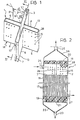
- the diffuser of the invention is indicated 1 and is constituted in the first embodiment by four diffuser elements (arms) 11, 12, 13, 14 which are disposed in a cross and each of which is formed by two substantially parallel walls; the walls 2 and 3 form the arm 11, the walls 4 and 5 form the arm 12, the walls 6 and 7 the arm 13, the walls 8 and 9 the arm 14.
- the adjacent walls of two consecutive arms (3, 4; 5, 6; 7, 8; 9, 2) form, in pairs, dihedrons with substantially parallel edges.
- a hole 10 for the immission of an oxygen-carrying gas is formed in the area of connection of two walls of any one arm, for example the arm 13.
- a plurality of apertures 1 of dimensions such as to promote the passage of the oxygen therethrough is formed in each of the eight walls 2-9 of the diffuser.
- FIG. 2 shows the principle structure of hollow-fibre oxygenators well known in the art, in median longitudinal section. The structure is illustrated in outline so as to show the insertion therein of the diffuser of the present invention.
- a generally cylindrical container houses a bundle 17 of hollow fibres of semi-permeable material with the dimensions given in the introduction to the present specification. Fibres having these characteristics are available commercially as is well known to experts in the art.
- Two zones of fixing of the fibres are indicated 18 and 19, the fixing being achieved by the introduction of an adhesive resin (generally polyurethane) between the fibres and its subsequent setting.
- Fibres of the bundle 17 pass through the zones 18 and 19 and face the respective surfaces 20, 21 presenting their hollow circular sections thereto.
- a collector for a first fluid - in this embodiment blood - coming from a nozzle 23 is indicated 22; the blood will enter the bundle of fibres 17 through their ends which open at the surface 21.
- a second collector is indicated 24, is arranged to receive the blood leaving the ends of the bundle of fibres 17 which open at the surface 20, the blood flowing out of the oxygenator through a nozzle 25.
- Oxygen is introduced through a nozzle 26 and diffuses between the fibres of the bundle 17 so as to replace the carbon dioxide in the blood during its passage between the fibres in counter-current to the blood which flows within the fibres, this exchange being possible because of the semi-permeable nature of the fibres themselves.
- the mixture of the remaining oxygen and the carbon dioxide removed finally leaves through a second nozzle 27.
- the diffuser 1 of Figure 1 is obviously shown in median section.
- the central zone 28 is the empty zone between the arms and corresponds to the area of connection between the walls 8 and 9 ( Figure 1) of the arm 14.
- the upper part 29 ( Figure 2) of the diffuser is inserted in the zone 18 of fixing of the fibres and is thus also fixed in the bonding resin. It does not reach the end surface 20 where the fibres open but remains embedded within the adhesive itself.
- the venous blood enters the nozzle 23, fills the collector 22, enters the bundle 17 of hollow fibres through their ends which are open at the surface 21, and then passes through them to their opposite ends facing the surface 20.
- a current of oxygen introduced by the nozzle 26 passes through the hole 10 of the diffuser 1 between the walls 6 and 7 of the arm 13, then diffuses into the arms 11, 12 and 14 through the apertures 15 present in the walls of the diffuser, and penetrates between the fibres of the bundle 17 to bathe them so completely as to be almost homogeneous.
- the gas pressure will not drop to such a level at any point in the bundle as to compromise its further advance, in that the path of the oxygen flow will always be much less than the radius of the bundle 2.
- the maximum path of the gas can be calculated from simple considerations of elementary geometry.
- the diffuser 1 ( Figure 1) is made from any plastics material which can be moulded into the desired form and perforated.
- it could be a polycarbonate or styrene - acrylonitrile or the like.
- the method of manufacture may consist, for example, of moulding two halves (wall 6, arm 12 and wall 3; wall 7, arm 14 and wall 2) which are mirror images because of the hole 10 which must be between the two facing halves. Methods of this type fall within the normal practice of moulded plastics technology.
- the fixing of the diffuser 1 within the bundle of fibres 17 ( Figure 2) is carried out simultaneously with the fixing of the fibres, for example, by the introduction of the adhesive into the bundle in the fluid state, followed by centrifuging and setting. These are also methods which are well known to the expert in the art.
- the insertion of the diffuser 1 into the bundle 17 does not cause disorder in the geometry of the fibres.
- the thickness of the arms is extremely small, in effect no greater than 2.5 mm, which is sufficient for the passage of the gas without a drop in pressure but far from creating alterations in the geometry of the bundle and preferential paths for the gas.
- the absence of changes in the geometry of the ordering of the fibres means that they come together at the end of the diffuser without twisting or stretching, and the absence of preferential paths for the gas achieves the specific function of the diffuser 1: to carry the oxygen without a pressure drop to all the fibres so that the bathing of the fibres in the last part of the gas path is practically homogeneous throughout the bundle.
- a second embodiment of the invention provides for the supply of the oxygen to a central position of the oxygenator.
- the diffuser takes on the form shown schematically and indicated 30 in Figure 3, in which the arms 31, 32, 33, 34 have an additional duct 35 which is parallel to them and to the edges of the dihedral components of the diffuser, and is located centrally relative to their spatial distribution.
- Figure 4 in which the general diagram of the oxygenator of Figure 2 is repeated in median longitudinal section, the location of the diffuser 30 of Figure 3 can be seen in a median section taken along the line 4-4.
- Figure 4 also shows the oxygen supply duct 35, the arms 32 and 34 of which only one wall is of course shown, and the empty zone 36 between the arms corresponding to the area of connection between the two walls of the arms 31 ( Figure 3).
- the oxygen enters through the nozzle 37 ( Figure 4) and the duct 35, flows into the central channel 36 of the diffuser 30 in the cross-shaped spaces between the arms 31, 32, 33, 34 ( Figure 3) of the diffuser itself, and passes through the apertures 38 in its walls between the fibres in which the blood to be oxygenated flows.
- the diffuser 30 is also made from plastics material and may be constructed by well-known moulding techniques.
- the duct 35 could be made in one piece with one half of the diffuser, for example the half including the arm 33.
- the diffuser both in the embodiment of Figure 1 and in that of Figure 3, may have a different number of arms from four as long as this number is equal to or greater than two.
- Figures 5, 6 and 7 illustrate, by way of example, three-armed, six-armed, and eight- armed diffusers, respectively, in accordance with the first embodiment. If the number of arms is increased, the homogeneity of the oxygenation of the fibres is increased.
- the walls have a plurality of apertures; the apertures could also be made in the areas of connection of the walls or only in these areas, causing the gas to pass through the peripheral zone of the bundle of fibres, which could be sufficient, particularly if there were a very high number of arms.
Landscapes
- Health & Medical Sciences (AREA)
- Urology & Nephrology (AREA)
- Heart & Thoracic Surgery (AREA)
- Emergency Medicine (AREA)
- Hematology (AREA)
- General Health & Medical Sciences (AREA)
- Anesthesiology (AREA)
- Biomedical Technology (AREA)
- Vascular Medicine (AREA)
- Life Sciences & Earth Sciences (AREA)
- Animal Behavior & Ethology (AREA)
- Engineering & Computer Science (AREA)
- Public Health (AREA)
- Veterinary Medicine (AREA)
- Chemical & Material Sciences (AREA)
- Chemical Kinetics & Catalysis (AREA)
- External Artificial Organs (AREA)
- Artificial Filaments (AREA)
Claims (8)
Priority Applications (1)
| Application Number | Priority Date | Filing Date | Title |
|---|---|---|---|
| AT86830261T ATE43969T1 (de) | 1985-09-24 | 1986-09-24 | Hohlfaser-blutoxygenatoren. |
Applications Claiming Priority (2)
| Application Number | Priority Date | Filing Date | Title |
|---|---|---|---|
| IT1740785 | 1985-09-24 | ||
| IT17407/85A IT1218450B (it) | 1985-09-24 | 1985-09-24 | Perfezionamenti agli ossigenatori per il sangue, a fibre cave |
Publications (2)
| Publication Number | Publication Date |
|---|---|
| EP0217759A1 EP0217759A1 (de) | 1987-04-08 |
| EP0217759B1 true EP0217759B1 (de) | 1989-06-14 |
Family
ID=11150227
Family Applications (1)
| Application Number | Title | Priority Date | Filing Date |
|---|---|---|---|
| EP86830261A Expired EP0217759B1 (de) | 1985-09-24 | 1986-09-24 | Hohlfaser-Blutoxygenatoren |
Country Status (5)
| Country | Link |
|---|---|
| US (1) | US4749551A (de) |
| EP (1) | EP0217759B1 (de) |
| AT (1) | ATE43969T1 (de) |
| DE (1) | DE3663884D1 (de) |
| IT (1) | IT1218450B (de) |
Cited By (1)
| Publication number | Priority date | Publication date | Assignee | Title |
|---|---|---|---|---|
| USRE36774E (en) | 1989-10-01 | 2000-07-11 | Baxter Healthcare Corporation | Cylindrical blood heater/oxygenator |
Families Citing this family (35)
| Publication number | Priority date | Publication date | Assignee | Title |
|---|---|---|---|---|
| US4980060A (en) * | 1987-07-13 | 1990-12-25 | Asahi Kasei Kogyo Kabushiki Kaisha | Hollow fiber membranes with fusion-bonded end portions |
| EP0394221B1 (de) * | 1987-07-28 | 1993-10-27 | Minntech Corporation | Blutoxygenerator vom äusseren perfusionstyp |
| AU611244B2 (en) * | 1987-12-25 | 1991-06-06 | Terumo Kabushiki Kaisha | Medical instrument |
| DE68922908T2 (de) * | 1989-01-13 | 1995-11-02 | Minntech Corp., Minneapolis, Minn. | Keilform für eine sauerstoffvorrichtung. |
| US5316724A (en) * | 1989-03-31 | 1994-05-31 | Baxter International Inc. | Multiple blood path membrane oxygenator |
| EP0465506B1 (de) * | 1989-03-31 | 1994-12-07 | Baxter International Inc. | Membranoxygenator |
| HUT64867A (en) * | 1989-10-01 | 1994-03-28 | Minntech Corp | Cylindrical water heater/oxydizer |
| US5578267A (en) * | 1992-05-11 | 1996-11-26 | Minntech Corporation | Cylindrical blood heater/oxygenator |
| IT1271104B (it) * | 1994-11-25 | 1997-05-26 | Dideco Spa | Ossigenatore di sangue con uno strato di capillari in membrana microporosa. |
| NL1004489C2 (nl) * | 1996-11-11 | 1998-05-14 | X Flow Bv | Filtratiemembraanmodule. |
| NL1008376C2 (nl) | 1998-02-20 | 1999-08-24 | X Flow Bv | Filtratiemembraanmodule. |
| US8828226B2 (en) | 2003-03-01 | 2014-09-09 | The Trustees Of Boston University | System for assessing the efficacy of stored red blood cells using microvascular networks |
| US8545754B2 (en) | 2009-04-23 | 2013-10-01 | Medtronic, Inc. | Radial design oxygenator with heat exchanger |
| US20120129149A1 (en) * | 2009-07-31 | 2012-05-24 | Federspiel William J | Removal of oxygen from biological fluids |
| US12089589B2 (en) | 2009-10-12 | 2024-09-17 | Hemanext Inc. | Irradiation of red blood cells and anaerobic storage |
| US11284616B2 (en) | 2010-05-05 | 2022-03-29 | Hemanext Inc. | Irradiation of red blood cells and anaerobic storage |
| US9199016B2 (en) | 2009-10-12 | 2015-12-01 | New Health Sciences, Inc. | System for extended storage of red blood cells and methods of use |
| CA2781866C (en) | 2009-10-12 | 2019-12-03 | New Health Sciences, Inc. | Blood storage bag system and depletion devices with oxygen and carbon dioxide depletion capabilities |
| WO2011046963A1 (en) | 2009-10-12 | 2011-04-21 | New Health Sciences, Inc. | Oxygen depletion devices and methods for removing oxygen from red blood cells |
| JP5930483B2 (ja) | 2010-08-25 | 2016-06-08 | ニュー・ヘルス・サイエンシーズ・インコーポレイテッドNew Health Sciences, Inc. | 保存中の赤血球の品質及び生存を高める方法 |
| ES2793484T3 (es) | 2010-11-05 | 2020-11-16 | Hemanext Inc | Irradiación de glóbulos rojos y almacenamiento anaeróbico |
| US9067004B2 (en) | 2011-03-28 | 2015-06-30 | New Health Sciences, Inc. | Method and system for removing oxygen and carbon dioxide during red cell blood processing using an inert carrier gas and manifold assembly |
| ES2923571T3 (es) | 2011-08-10 | 2022-09-28 | Hemanext Inc | Dispositivo integrado de filtrado de leucocitos, oxígeno y/o CO2 y separación de plasma |
| US9561315B1 (en) * | 2013-02-19 | 2017-02-07 | Jay Vincelli | Miniaturized cardiopulmonary bypass circuit for a mouse model |
| US9877476B2 (en) | 2013-02-28 | 2018-01-30 | New Health Sciences, Inc. | Gas depletion and gas addition devices for blood treatment |
| WO2015153370A2 (en) | 2014-03-29 | 2015-10-08 | Labib Mohamed E | Blood processing cartridges and systems, and methods for extracorporeal blood therapies |
| MX2017011595A (es) | 2015-03-10 | 2018-06-15 | New Health Sciences Inc | Kits, dispositivos descartables para reducir el oxígeno y métodos para usarlos. |
| AU2016253005B2 (en) | 2015-04-23 | 2020-07-09 | Hemanext Inc. | Anaerobic blood storage containers |
| BR122021024421B1 (pt) | 2015-05-18 | 2022-05-03 | Hemanext Inc | Usos de um produto de sangue total armazenado reduzido de oxigênio com plaquetas |
| US10426884B2 (en) | 2015-06-26 | 2019-10-01 | Novaflux Inc. | Cartridges and systems for outside-in flow in membrane-based therapies |
| EP3352888B8 (de) | 2015-09-24 | 2022-01-12 | Princeton Trade and Technology Inc. | Kartuschen für hohlfasermembranbasierte therapien |
| WO2017205590A2 (en) | 2016-05-27 | 2017-11-30 | New Health Sciences, Inc. | Anaerobic blood storage and pathogen inactivation method |
| EP3731892B1 (de) | 2018-03-02 | 2022-08-24 | Spectrum Medical Ltd. | Oxygenierungssystem |
| US12268802B2 (en) | 2019-04-09 | 2025-04-08 | The Children's Hospital Of Philadelphia | Oxygenator for use with extracorporeal support of premature fetus |
| GB2583532B (en) | 2019-05-03 | 2023-04-05 | Spectrum Medical Ltd | Control system |
Family Cites Families (8)
| Publication number | Priority date | Publication date | Assignee | Title |
|---|---|---|---|---|
| GB1220924A (en) * | 1967-05-13 | 1971-01-27 | Bp Chem Int Ltd | Reaction vessel for contacting liquids and gas |
| JPS5238000B1 (de) * | 1967-04-01 | 1977-09-26 | ||
| US3769162A (en) * | 1971-08-26 | 1973-10-30 | R Brumfield | Blood oxygenator and thermoregulator apparatus |
| US4048072A (en) * | 1975-10-23 | 1977-09-13 | Schramm, Inc. | Air diffusers |
| US4240907A (en) * | 1976-07-23 | 1980-12-23 | Bentley Laboratories, Inc. | Dialyzer and method of dialysis |
| FR2374933A1 (fr) * | 1976-12-24 | 1978-07-21 | Rhone Poulenc Ind | Appareil a fibres creuses, utilisable notamment comme rein artificiel, et procede pour sa fabrication |
| US4365978A (en) * | 1980-03-25 | 1982-12-28 | Shell Oil Company | Storage of liquid hydrocarbons in salt dome caverns |
| JPS5739854A (en) * | 1980-08-25 | 1982-03-05 | Terumo Corp | Hollow fiber type artificial lung building in heat exchanger |
-
1985
- 1985-09-24 IT IT17407/85A patent/IT1218450B/it active
-
1986
- 1986-09-22 US US06/910,411 patent/US4749551A/en not_active Expired - Fee Related
- 1986-09-24 EP EP86830261A patent/EP0217759B1/de not_active Expired
- 1986-09-24 AT AT86830261T patent/ATE43969T1/de not_active IP Right Cessation
- 1986-09-24 DE DE8686830261T patent/DE3663884D1/de not_active Expired
Cited By (1)
| Publication number | Priority date | Publication date | Assignee | Title |
|---|---|---|---|---|
| USRE36774E (en) | 1989-10-01 | 2000-07-11 | Baxter Healthcare Corporation | Cylindrical blood heater/oxygenator |
Also Published As
| Publication number | Publication date |
|---|---|
| DE3663884D1 (en) | 1989-07-20 |
| ATE43969T1 (de) | 1989-06-15 |
| US4749551A (en) | 1988-06-07 |
| IT8517407A0 (it) | 1985-09-24 |
| EP0217759A1 (de) | 1987-04-08 |
| IT1218450B (it) | 1990-04-19 |
Similar Documents
| Publication | Publication Date | Title |
|---|---|---|
| US4749551A (en) | Hollow-fiber oxygenators for blood | |
| US5395525A (en) | Apparatus for exchanging substances | |
| JP7393327B2 (ja) | 呼吸補助のためのデュアルチャンバガス交換器とその使用方法 | |
| US4902476A (en) | Heat exchanger and blood oxygenator apparatus | |
| US5236665A (en) | Hollow fiber treatment apparatus and membrane oxygenator | |
| US6454999B1 (en) | Integrated blood pump and oxygenator system having extended blood flow path | |
| US5823987A (en) | Compact membrane-type blood oxygenator with concentric heat exchanger | |
| US6723284B1 (en) | Membrane apparatus with enhanced mass transfer, heat transfer and pumping capabilities via active mixing | |
| EP0876170B1 (de) | Blutoxygenator mit wärmeaustauscher | |
| AU763508B2 (en) | Membrane apparatus with enhanced mass transfer, heat transfer and pumping capabilities via active mixing | |
| US6106776A (en) | Membrane apparatus with enhanced mass transfer via active mixing | |
| EP0003495A1 (de) | Vorrichtung für die Diffusion von Substanzen zwischen zwei durch eine halbdurchlässige Membran voneinander getrennten Fluiden | |
| US4556489A (en) | Membrane oxygenator | |
| US4297318A (en) | Blood oxygenator | |
| EP0114732A2 (de) | Blutoxygenator | |
| US4237013A (en) | Hollow fiber permeability apparatus | |
| US4082670A (en) | Hollow fiber permeability apparatus | |
| AU675496B2 (en) | Hollow fiber blood oxygenator | |
| US5922202A (en) | Inlet manifold for blood oxygenator apparatus | |
| JPH04193178A (ja) | 中空糸膜型人工肺モジュール | |
| US5858233A (en) | Transition manifold for blood oxygenator apparatus | |
| CA2081206A1 (en) | Hollow fiber fluid treatment apparatus and membrane oxygenator | |
| JPH0439862B2 (de) | ||
| EP0157941B1 (de) | Blutoxygenator mit einer Hohlfasermembran | |
| JPS6311972Y2 (de) |
Legal Events
| Date | Code | Title | Description |
|---|---|---|---|
| PUAI | Public reference made under article 153(3) epc to a published international application that has entered the european phase |
Free format text: ORIGINAL CODE: 0009012 |
|
| AK | Designated contracting states |
Kind code of ref document: A1 Designated state(s): AT BE CH DE FR GB IT LI LU NL SE |
|
| 17P | Request for examination filed |
Effective date: 19870320 |
|
| 17Q | First examination report despatched |
Effective date: 19880621 |
|
| GRAA | (expected) grant |
Free format text: ORIGINAL CODE: 0009210 |
|
| AK | Designated contracting states |
Kind code of ref document: B1 Designated state(s): AT BE CH DE FR GB IT LI LU NL SE |
|
| REF | Corresponds to: |
Ref document number: 43969 Country of ref document: AT Date of ref document: 19890615 Kind code of ref document: T |
|
| ITF | It: translation for a ep patent filed | ||
| REF | Corresponds to: |
Ref document number: 3663884 Country of ref document: DE Date of ref document: 19890720 |
|
| PGFP | Annual fee paid to national office [announced via postgrant information from national office to epo] |
Ref country code: AT Payment date: 19890804 Year of fee payment: 4 |
|
| PGFP | Annual fee paid to national office [announced via postgrant information from national office to epo] |
Ref country code: SE Payment date: 19890808 Year of fee payment: 4 |
|
| PGFP | Annual fee paid to national office [announced via postgrant information from national office to epo] |
Ref country code: CH Payment date: 19890811 Year of fee payment: 4 |
|
| PGFP | Annual fee paid to national office [announced via postgrant information from national office to epo] |
Ref country code: BE Payment date: 19890818 Year of fee payment: 4 |
|
| PGFP | Annual fee paid to national office [announced via postgrant information from national office to epo] |
Ref country code: LU Payment date: 19890824 Year of fee payment: 4 |
|
| PG25 | Lapsed in a contracting state [announced via postgrant information from national office to epo] |
Ref country code: LU Free format text: LAPSE BECAUSE OF NON-PAYMENT OF DUE FEES Effective date: 19890930 |
|
| PGFP | Annual fee paid to national office [announced via postgrant information from national office to epo] |
Ref country code: NL Payment date: 19890930 Year of fee payment: 4 |
|
| ET | Fr: translation filed | ||
| PLBE | No opposition filed within time limit |
Free format text: ORIGINAL CODE: 0009261 |
|
| STAA | Information on the status of an ep patent application or granted ep patent |
Free format text: STATUS: NO OPPOSITION FILED WITHIN TIME LIMIT |
|
| 26N | No opposition filed | ||
| PG25 | Lapsed in a contracting state [announced via postgrant information from national office to epo] |
Ref country code: AT Effective date: 19900924 |
|
| PG25 | Lapsed in a contracting state [announced via postgrant information from national office to epo] |
Ref country code: SE Effective date: 19900925 |
|
| PGFP | Annual fee paid to national office [announced via postgrant information from national office to epo] |
Ref country code: FR Payment date: 19900928 Year of fee payment: 5 |
|
| PG25 | Lapsed in a contracting state [announced via postgrant information from national office to epo] |
Ref country code: LI Effective date: 19900930 Ref country code: CH Effective date: 19900930 Ref country code: BE Effective date: 19900930 |
|
| BERE | Be: lapsed |
Owner name: SORIN BIOMEDICA S.P.A. Effective date: 19900930 |
|
| PG25 | Lapsed in a contracting state [announced via postgrant information from national office to epo] |
Ref country code: NL Effective date: 19910401 |
|
| NLV4 | Nl: lapsed or anulled due to non-payment of the annual fee | ||
| REG | Reference to a national code |
Ref country code: CH Ref legal event code: PL |
|
| PG25 | Lapsed in a contracting state [announced via postgrant information from national office to epo] |
Ref country code: FR Effective date: 19920529 |
|
| REG | Reference to a national code |
Ref country code: FR Ref legal event code: ST |
|
| ITTA | It: last paid annual fee | ||
| EUG | Se: european patent has lapsed |
Ref document number: 86830261.3 Effective date: 19910527 |
|
| ITPR | It: changes in ownership of a european patent |
Owner name: CONFERIMENTO;SORIN BIOMEDICA CARDIO S.P.A. |
|
| REG | Reference to a national code |
Ref country code: GB Ref legal event code: 732E |
|
| REG | Reference to a national code |
Ref country code: GB Ref legal event code: IF02 |
|
| PGFP | Annual fee paid to national office [announced via postgrant information from national office to epo] |
Ref country code: GB Payment date: 20020815 Year of fee payment: 17 |
|
| PGFP | Annual fee paid to national office [announced via postgrant information from national office to epo] |
Ref country code: DE Payment date: 20020822 Year of fee payment: 17 |
|
| PG25 | Lapsed in a contracting state [announced via postgrant information from national office to epo] |
Ref country code: GB Free format text: LAPSE BECAUSE OF NON-PAYMENT OF DUE FEES Effective date: 20030924 |
|
| PG25 | Lapsed in a contracting state [announced via postgrant information from national office to epo] |
Ref country code: DE Free format text: LAPSE BECAUSE OF NON-PAYMENT OF DUE FEES Effective date: 20040401 |
|
| GBPC | Gb: european patent ceased through non-payment of renewal fee |
Effective date: 20030924 |
|
| PG25 | Lapsed in a contracting state [announced via postgrant information from national office to epo] |
Ref country code: IT Free format text: LAPSE BECAUSE OF NON-PAYMENT OF DUE FEES;WARNING: LAPSES OF ITALIAN PATENTS WITH EFFECTIVE DATE BEFORE 2007 MAY HAVE OCCURRED AT ANY TIME BEFORE 2007. THE CORRECT EFFECTIVE DATE MAY BE DIFFERENT FROM THE ONE RECORDED. Effective date: 20050924 |