EP0217773A1 - Mähvorrichtung - Google Patents
Mähvorrichtung Download PDFInfo
- Publication number
- EP0217773A1 EP0217773A1 EP86850320A EP86850320A EP0217773A1 EP 0217773 A1 EP0217773 A1 EP 0217773A1 EP 86850320 A EP86850320 A EP 86850320A EP 86850320 A EP86850320 A EP 86850320A EP 0217773 A1 EP0217773 A1 EP 0217773A1
- Authority
- EP
- European Patent Office
- Prior art keywords
- cutting
- cutting attachment
- attachment
- mower
- mower according
- Prior art date
- Legal status (The legal status is an assumption and is not a legal conclusion. Google has not performed a legal analysis and makes no representation as to the accuracy of the status listed.)
- Granted
Links
- 230000033001 locomotion Effects 0.000 claims abstract description 12
- 238000006073 displacement reaction Methods 0.000 claims abstract 4
- 230000000063 preceeding effect Effects 0.000 claims 2
- 230000005540 biological transmission Effects 0.000 claims 1
- 229910000831 Steel Inorganic materials 0.000 description 1
- 230000000994 depressogenic effect Effects 0.000 description 1
- 239000004033 plastic Substances 0.000 description 1
- 229920003023 plastic Polymers 0.000 description 1
- 239000010959 steel Substances 0.000 description 1
Images


Classifications
-
- A—HUMAN NECESSITIES
- A01—AGRICULTURE; FORESTRY; ANIMAL HUSBANDRY; HUNTING; TRAPPING; FISHING
- A01D—HARVESTING; MOWING
- A01D34/00—Mowers; Mowing apparatus of harvesters
- A01D34/01—Mowers; Mowing apparatus of harvesters characterised by features relating to the type of cutting apparatus
- A01D34/412—Mowers; Mowing apparatus of harvesters characterised by features relating to the type of cutting apparatus having rotating cutters
- A01D34/63—Mowers; Mowing apparatus of harvesters characterised by features relating to the type of cutting apparatus having rotating cutters having cutters rotating about a vertical axis
- A01D34/64—Mowers; Mowing apparatus of harvesters characterised by features relating to the type of cutting apparatus having rotating cutters having cutters rotating about a vertical axis mounted on a vehicle, e.g. a tractor, or drawn by an animal or a vehicle
- A01D2034/645—Lifting means for the cutter of the lawnmower mounted at the front of the vehicle for inspection and maintenance
-
- A—HUMAN NECESSITIES
- A01—AGRICULTURE; FORESTRY; ANIMAL HUSBANDRY; HUNTING; TRAPPING; FISHING
- A01D—HARVESTING; MOWING
- A01D2101/00—Lawn-mowers
Definitions
- This invention relates to a ride-on mower comprising a chassis supporting a driving unit intended to propell the wheels of the mower as well as a cutting attachment the cutting attachment being movably fastened to the chassis and by means of an operating device can be brought from a lower cutting position to an upper non cutting position.
- Mowers of the above type are previously known, the operating device usually being a bar which is moved between two different positions, one position corresponding to a tilted up position of the cutting attachment and the other corresponding to a cutting position.
- the driving of the cutting attachment there is a separate bar. In order to adjust the cutting height for this type of machine another bar is used which is fastened to the cutting attachment.
- a further advantage of a device according to the invention is that the bar for adjusting the cutting height and the engagement and disengagement of the cutting attachment are intergrated in the same unit which makes it very easy to operate the machine.
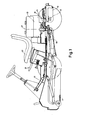
- Fig.1 is a schematic vertical section of a device according to the invention.
- Fig. 2 is a vertical section of the support of the cutting attachment and
- Fig. 3 is a section of the operating device.
- the mower comprises a front chassis section 10 supporting a cutting attachment 11 a seat 12 and a driving unit 13 and a rear chassis section 14 supporting a gear box 15 and a rear shaft 16.
- the front and the rear section are pivotally connected to each other and can be turned about a common vertical axis 17.
- the rear section is so designed that it can swing about a horisontal axis 18.
- the bar acts on the cutting attachment 11 by means of a link arm mechanism described below so that it can be positioned in different cutting heights as well as be moved from a cutting to a non-cutting position.
- the bar 19 can be turned about a dowel 20 and comprises two hooks 21 and 22 respectively which can be brought into engagement with teeth 23 and 24 respectively on a plate 25 fixed to the chassis.
- the hook 21 is placed at one end of a rocker arm 26 which turns about a dowel 27 which is fixed to the bar 19.
- the other end of the rocker arm is at a point 28 turnably connected to a rod 29 which is under the influence of a spring 30.
- the spring in turn pushes the hook 21 towards the plate 25.
- the spring is clamped between a bracket 31 on the bar 19 and a knob 32 screwed to the rod.
- the knob 32 the hook 21 can be acted on so that it disengages from the tooth 23.
- the hook 22 is a bent outer part of a plate 33 which continues into a slide 35 which is provided with several recesses 34, the slide being movable in the direction of the bar by means of a knob 36.
- the slide 35 can be locked in certain positions since a tongue 37 on the bar 19 engages one of the resseses 34.
- the knob 36 the hook 22 can be positioned so that it engages a suitable tooth 24.
- the bar which is placed at one side of the chassis is by means of a draw bar 38 connected to a three armed follower 39 which is connected to a shaft 40 which is turnably fastened to the chassis.
- this shaft supports another follower not shown intended to act on the type of link arm mechanism which will be described with reference to the figures.
- the shaft 40 also supports a mainly U-shaped yoke 41 comprising two parallel pipes 42 placed one on each side of the cutter attachment. These pipes are turnably fastened to the shaft 40.
- the pipes have a horisontal inner part and a vertical outer part and are via a pipe 43 connected to each other, the pipe 43 serving as a bearing for several rollers 44 which are intended to rest on the ground during cutting.
- the pipes 42 each have an ear 45 to which an angled link arm 46 is turnably fastened.
- One end of the link arm 46 supports a draw bar 47 the other end of which is connected to a first arm 48 of the three arm follower 39.
- the other end of the link arm 46 is turnably fastened to a lever 49 extending between the vertical part of the pipe 42 and a second arm 50 of the follower 39.
- the end of the link arm 50 which is in touch with the pipe 42 is shaped as a fork 51 and intended to slide on the pipe whereas its second end has a slot 52 in which a dowel 53 of the second arm 50 slides.
- the third arm 54 of the follower is via a drawbar 55 connected to a tension roller 56 (Fig. 1) in order to act on a belt, not shown in detail, running between the driving unit and the cutting attachment.
- the yoke 41 has at its front part a fastening means 57 by means of which a guard 58 preferably of plastics is fastened to the yoke.
- the guard is mainly U-shaped and covers the front side of the cutting attachment as well as its sides.
- the upper part of the guard is placed closely outside a steelplate 59 on the chassis and has a flange 60 which in a lower position engages a flange 61 on the steel plate 59.
- At the lower part of the guard there is at its front end an opening 62 which means that small objects do not hinder the movement of the mower.
- a pipe 63 which is fixed to the guard.
- This pipe is bend and turnably fastened to the pipe 43 by means of the fastening means 57 which means that the guard follows the movement of the rollers on the ground during cutting.
- the fastening means 57 also supports a turning stop 64 keeping the guard parallel to ground by cooperation with the stay 65 extending between the vertical parts of the pipe 42.
- the cutting attachment has several pulleys 66 each driving a knife in the cutter attachment and the chassis has a corresponding number of braking rubber blocks 67. These blocks are placed so that they engage the pulleys when the cutting attachment is swung to its inactive upper position that is the dash dottet position shown in Fig. 2. These blocks also are a spring support of the cutting attachment in its upper position by means of which rattling and noice is avoided when the mower is driven.
- the device operates in the following way.
- the bar 19 In its disconnected position the bar 19 is mainly vertical and the hook 21 engages the tooth 23 of the plate 25.
- the knob 36 is depressed which means that the slide 35 disengages from tongue 37 so that it can be moved in the direction of the bar.
- the hook 22 is also moved in the length direction of the bar so that the hook 22 when moving the bar forwards downwards in Fig. 2 engages one of the teeth 24 of the plate 25 thereby preventing the bar 19 from being moved further forwards.
- the hook 21 For moving the cutting attachment to cutting position the hook 21 is moved out of engagement with the tooth 23 by acting on the knob 32.
- the preset cutting height is maintained by means of the rollers 44 any ridges or recesses of the lawn causing a corresponding increase or decrease of the cutting height depending on that the rear part of the lever 49 is kept at a certain distance from the ground whereas the front part of the lever is subject to the changes of the ground level.
Landscapes
- Life Sciences & Earth Sciences (AREA)
- Environmental Sciences (AREA)
- Harvester Elements (AREA)
- Measurement Of Radiation (AREA)
- Transplanting Machines (AREA)
- Investigating Or Analysing Biological Materials (AREA)
- Photoreceptors In Electrophotography (AREA)
- Acyclic And Carbocyclic Compounds In Medicinal Compositions (AREA)
- Polysaccharides And Polysaccharide Derivatives (AREA)
Priority Applications (1)
| Application Number | Priority Date | Filing Date | Title |
|---|---|---|---|
| AT86850320T ATE57594T1 (de) | 1985-09-27 | 1986-09-19 | Maehvorrichtung. |
Applications Claiming Priority (2)
| Application Number | Priority Date | Filing Date | Title |
|---|---|---|---|
| SE8504493A SE454039B (sv) | 1985-09-27 | 1985-09-27 | Akbar gresklippare |
| SE8504493 | 1985-09-27 |
Publications (2)
| Publication Number | Publication Date |
|---|---|
| EP0217773A1 true EP0217773A1 (de) | 1987-04-08 |
| EP0217773B1 EP0217773B1 (de) | 1990-10-24 |
Family
ID=20361552
Family Applications (1)
| Application Number | Title | Priority Date | Filing Date |
|---|---|---|---|
| EP86850320A Expired - Lifetime EP0217773B1 (de) | 1985-09-27 | 1986-09-19 | Mähvorrichtung |
Country Status (11)
| Country | Link |
|---|---|
| US (1) | US4934130A (de) |
| EP (1) | EP0217773B1 (de) |
| JP (1) | JPH0669327B2 (de) |
| AT (1) | ATE57594T1 (de) |
| AU (1) | AU590897B2 (de) |
| CA (1) | CA1289751C (de) |
| DE (1) | DE3675137D1 (de) |
| DK (1) | DK160662C (de) |
| FI (1) | FI82585C (de) |
| NZ (1) | NZ217591A (de) |
| SE (1) | SE454039B (de) |
Cited By (1)
| Publication number | Priority date | Publication date | Assignee | Title |
|---|---|---|---|---|
| EP0951816A1 (de) | 1998-04-24 | 1999-10-27 | Roberine BV | Grundstückspflegefahrzeug mit einem Arbeitsgerät |
Families Citing this family (12)
| Publication number | Priority date | Publication date | Assignee | Title |
|---|---|---|---|---|
| SE454127B (sv) * | 1985-08-08 | 1988-04-11 | Husqvarna Ab | Akbar gresklippare |
| US5138825A (en) * | 1990-12-11 | 1992-08-18 | Noma Outdoor Products, Inc. | Riding mower having a pedal operated height adjustment mechanism, air assisted discharge, and improved hydrostatic shift linkage |
| DE4208897C2 (de) * | 1992-03-19 | 1995-02-23 | Voith Gmbh J M | Auftragswerk zum Beschichten von Bahnen aus Papier oder Karton |
| IL113913A (en) * | 1995-05-30 | 2000-02-29 | Friendly Machines Ltd | Navigation method and system |
| JP3192065B2 (ja) * | 1995-08-31 | 2001-07-23 | 株式会社クボタ | フロントマウント型乗用芝刈り機 |
| AUPO674397A0 (en) * | 1997-05-12 | 1997-06-05 | Rover Mowers Limited | Improvements relating to mowers |
| SE512223C2 (sv) | 1998-06-26 | 2000-02-14 | Electrolux Ab | Anordning vid en åkgräsklippare för åstadkommande av ett serviceläge |
| DE102004053002A1 (de) * | 2004-11-03 | 2006-05-11 | Amazonen-Werke H. Dreyer Gmbh & Co. Kg | Selbstfahrendes Mähgerät |
| JP5213624B2 (ja) * | 2008-03-27 | 2013-06-19 | 中国電力株式会社 | 除草機 |
| EP3531818B1 (de) * | 2017-04-04 | 2022-09-14 | Husqvarna AB | Rasenpflegeaufsitzfahrzeug mit schneiddeckhöhenverstellsystem |
| EP3780933B1 (de) * | 2018-09-14 | 2023-11-08 | Husqvarna Ab | Multipositionssverriegelungsmechanismus für ein sitzfahrzeug zur rasenpflege |
| US12426543B2 (en) | 2020-11-11 | 2025-09-30 | Techtronic Cordless Gp | Lawn mowers, detachable mower decks, and methods associated therewith |
Citations (11)
| Publication number | Priority date | Publication date | Assignee | Title |
|---|---|---|---|---|
| US3283486A (en) * | 1964-05-01 | 1966-11-08 | Int Harvester Co | Implement supporting and lift linkage |
| US3461654A (en) * | 1967-03-15 | 1969-08-19 | M T & D Co The | Mechanism for raising and lowering cutter unit and for concurrently controlling operation of the cutter unit |
| US3654749A (en) * | 1970-10-05 | 1972-04-11 | Sperry Rand Corp | Mower mounting linkage |
| US3672137A (en) * | 1970-10-26 | 1972-06-27 | Int Harvester Co | Mower support and lift linkage |
| FR2145322A5 (de) * | 1971-07-07 | 1973-02-16 | Sperry Rand Corp | |
| US3839919A (en) * | 1971-04-08 | 1974-10-08 | Ariens Co | Riding mower |
| FR2374835A1 (fr) * | 1976-12-27 | 1978-07-21 | Massey Ferguson Inc | Dispositif de support d'outil pour tracteur |
| DE2840691A1 (de) * | 1978-09-19 | 1980-04-03 | Wilfried Bruns | Schlepper mit sichelmaeher |
| US4442660A (en) * | 1982-08-30 | 1984-04-17 | Deere & Company | High lift mechanism for rear end of front mounted mower |
| EP0144214A2 (de) * | 1983-11-30 | 1985-06-12 | Honda Giken Kogyo Kabushiki Kaisha | Mähvorrichtung mit Schnitt-Höhen-Anzeige |
| EP0155437A1 (de) * | 1983-12-20 | 1985-09-25 | SIAG S.p.A. | Von einem sitzenden Fahrer gelenkter Rasenmäher mit rotierenden Messern |
Family Cites Families (12)
| Publication number | Priority date | Publication date | Assignee | Title |
|---|---|---|---|---|
| US3245209A (en) * | 1964-11-20 | 1966-04-12 | Int Harvester Co | Rotary mower with means providing selective suction for its blades |
| US3796028A (en) * | 1972-12-04 | 1974-03-12 | Fmc Corp | Implement lift hitch |
| US3874150A (en) * | 1973-06-25 | 1975-04-01 | Fmc Corp | Implement leveling system |
| US4084395A (en) * | 1974-11-01 | 1978-04-18 | Nannen William G | Working vehicle |
| US4320616A (en) * | 1980-12-18 | 1982-03-23 | J. I. Case Company | Lawn mower suspension |
| AU542239B2 (en) * | 1980-12-24 | 1985-02-14 | Reinhold, T.W. | Ride-on lawn mower |
| JPS57115810U (de) * | 1981-01-13 | 1982-07-17 | ||
| JPS58194620U (ja) * | 1982-06-22 | 1983-12-24 | 株式会社クボタ | 草刈用作業車 |
| US4563019A (en) * | 1983-12-22 | 1986-01-07 | Deere & Company | Latch assembly for holding a front mounted implement in raised position |
| US4551967A (en) * | 1985-03-04 | 1985-11-12 | Murcko Joseph S | Combination lawnmower and edger |
| SE454127B (sv) * | 1985-08-08 | 1988-04-11 | Husqvarna Ab | Akbar gresklippare |
| US4663923A (en) * | 1985-11-05 | 1987-05-12 | Ferris Industries, Inc. | Self-propelled mower |
-
1985
- 1985-09-27 SE SE8504493A patent/SE454039B/sv not_active IP Right Cessation
-
1986
- 1986-09-15 DK DK441186A patent/DK160662C/da not_active IP Right Cessation
- 1986-09-15 AU AU62667/86A patent/AU590897B2/en not_active Ceased
- 1986-09-16 NZ NZ217591A patent/NZ217591A/xx unknown
- 1986-09-19 EP EP86850320A patent/EP0217773B1/de not_active Expired - Lifetime
- 1986-09-19 AT AT86850320T patent/ATE57594T1/de not_active IP Right Cessation
- 1986-09-19 DE DE8686850320T patent/DE3675137D1/de not_active Expired - Fee Related
- 1986-09-25 FI FI863879A patent/FI82585C/fi not_active IP Right Cessation
- 1986-09-26 CA CA000519134A patent/CA1289751C/en not_active Expired - Fee Related
- 1986-09-26 JP JP61226303A patent/JPH0669327B2/ja not_active Expired - Lifetime
-
1988
- 1988-09-28 US US07/310,604 patent/US4934130A/en not_active Expired - Fee Related
Patent Citations (11)
| Publication number | Priority date | Publication date | Assignee | Title |
|---|---|---|---|---|
| US3283486A (en) * | 1964-05-01 | 1966-11-08 | Int Harvester Co | Implement supporting and lift linkage |
| US3461654A (en) * | 1967-03-15 | 1969-08-19 | M T & D Co The | Mechanism for raising and lowering cutter unit and for concurrently controlling operation of the cutter unit |
| US3654749A (en) * | 1970-10-05 | 1972-04-11 | Sperry Rand Corp | Mower mounting linkage |
| US3672137A (en) * | 1970-10-26 | 1972-06-27 | Int Harvester Co | Mower support and lift linkage |
| US3839919A (en) * | 1971-04-08 | 1974-10-08 | Ariens Co | Riding mower |
| FR2145322A5 (de) * | 1971-07-07 | 1973-02-16 | Sperry Rand Corp | |
| FR2374835A1 (fr) * | 1976-12-27 | 1978-07-21 | Massey Ferguson Inc | Dispositif de support d'outil pour tracteur |
| DE2840691A1 (de) * | 1978-09-19 | 1980-04-03 | Wilfried Bruns | Schlepper mit sichelmaeher |
| US4442660A (en) * | 1982-08-30 | 1984-04-17 | Deere & Company | High lift mechanism for rear end of front mounted mower |
| EP0144214A2 (de) * | 1983-11-30 | 1985-06-12 | Honda Giken Kogyo Kabushiki Kaisha | Mähvorrichtung mit Schnitt-Höhen-Anzeige |
| EP0155437A1 (de) * | 1983-12-20 | 1985-09-25 | SIAG S.p.A. | Von einem sitzenden Fahrer gelenkter Rasenmäher mit rotierenden Messern |
Cited By (2)
| Publication number | Priority date | Publication date | Assignee | Title |
|---|---|---|---|---|
| EP0951816A1 (de) | 1998-04-24 | 1999-10-27 | Roberine BV | Grundstückspflegefahrzeug mit einem Arbeitsgerät |
| US6631608B1 (en) | 1998-04-24 | 2003-10-14 | Roberine Bv | Extendable tool attachment mechanism for a lawn care vehicle |
Also Published As
| Publication number | Publication date |
|---|---|
| DE3675137D1 (de) | 1990-11-29 |
| DK441186D0 (da) | 1986-09-15 |
| CA1289751C (en) | 1991-10-01 |
| US4934130A (en) | 1990-06-19 |
| SE454039B (sv) | 1988-03-28 |
| DK441186A (da) | 1987-03-28 |
| FI863879A0 (fi) | 1986-09-25 |
| DK160662C (da) | 1991-09-16 |
| ATE57594T1 (de) | 1990-11-15 |
| JPH0669327B2 (ja) | 1994-09-07 |
| FI863879L (fi) | 1987-03-28 |
| EP0217773B1 (de) | 1990-10-24 |
| SE8504493D0 (sv) | 1985-09-27 |
| FI82585C (fi) | 1991-04-10 |
| SE8504493L (sv) | 1987-03-28 |
| FI82585B (fi) | 1990-12-31 |
| AU6266786A (en) | 1987-04-02 |
| NZ217591A (en) | 1989-01-27 |
| JPS6274210A (ja) | 1987-04-06 |
| AU590897B2 (en) | 1989-11-23 |
| DK160662B (da) | 1991-04-08 |
Similar Documents
| Publication | Publication Date | Title |
|---|---|---|
| EP0217773A1 (de) | Mähvorrichtung | |
| US4551967A (en) | Combination lawnmower and edger | |
| US5138825A (en) | Riding mower having a pedal operated height adjustment mechanism, air assisted discharge, and improved hydrostatic shift linkage | |
| CA1274398A (en) | Mower | |
| US3422553A (en) | Snow blade attachment | |
| US4441735A (en) | Steering gear assembly for a lawn and garden tractor | |
| US3628315A (en) | Mower safety device | |
| EP0155437A1 (de) | Von einem sitzenden Fahrer gelenkter Rasenmäher mit rotierenden Messern | |
| EP0966876B1 (de) | Selbstfahrender mäher | |
| US4760687A (en) | Mower deck height and clutch control | |
| US3839919A (en) | Riding mower | |
| US2947132A (en) | Wheel adjustment and driving in a power mower or the like | |
| US3263406A (en) | Front mounting for rotary type mower | |
| EP0478020B1 (de) | Rasenmäher mit in verschiedene Schnitthöhen verstellbare Stützroller und Hinterräder | |
| US4984417A (en) | Edger with belt braking device | |
| AU647678B2 (en) | Edger | |
| CA1137764A (en) | Safety control for riding lawn mower | |
| US11007963B2 (en) | Work vehicle having ROPS | |
| JPS5841811Y2 (ja) | コンバイン | |
| JPH09107775A (ja) | コンバイン | |
| JPS6134980Y2 (de) | ||
| JPH0947136A (ja) | 芝刈作業機の安全機構 | |
| JPH0514734Y2 (de) | ||
| JP3014546B2 (ja) | 芝刈機の刈高調整装置 | |
| JPH083247Y2 (ja) | 刈取収穫機の刈取クラッチ操作装置 |
Legal Events
| Date | Code | Title | Description |
|---|---|---|---|
| PUAI | Public reference made under article 153(3) epc to a published international application that has entered the european phase |
Free format text: ORIGINAL CODE: 0009012 |
|
| AK | Designated contracting states |
Kind code of ref document: A1 Designated state(s): AT DE FR GB IT SE |
|
| 17P | Request for examination filed |
Effective date: 19870925 |
|
| 17Q | First examination report despatched |
Effective date: 19890720 |
|
| GRAA | (expected) grant |
Free format text: ORIGINAL CODE: 0009210 |
|
| AK | Designated contracting states |
Kind code of ref document: B1 Designated state(s): AT DE FR GB IT SE |
|
| PG25 | Lapsed in a contracting state [announced via postgrant information from national office to epo] |
Ref country code: SE Effective date: 19901024 |
|
| REF | Corresponds to: |
Ref document number: 57594 Country of ref document: AT Date of ref document: 19901115 Kind code of ref document: T |
|
| REF | Corresponds to: |
Ref document number: 3675137 Country of ref document: DE Date of ref document: 19901129 |
|
| ITF | It: translation for a ep patent filed | ||
| ET | Fr: translation filed | ||
| PLBE | No opposition filed within time limit |
Free format text: ORIGINAL CODE: 0009261 |
|
| STAA | Information on the status of an ep patent application or granted ep patent |
Free format text: STATUS: NO OPPOSITION FILED WITHIN TIME LIMIT |
|
| ITTA | It: last paid annual fee | ||
| 26N | No opposition filed | ||
| PGFP | Annual fee paid to national office [announced via postgrant information from national office to epo] |
Ref country code: FR Payment date: 19990909 Year of fee payment: 14 |
|
| PGFP | Annual fee paid to national office [announced via postgrant information from national office to epo] |
Ref country code: AT Payment date: 19990913 Year of fee payment: 14 |
|
| PGFP | Annual fee paid to national office [announced via postgrant information from national office to epo] |
Ref country code: GB Payment date: 19990915 Year of fee payment: 14 |
|
| PGFP | Annual fee paid to national office [announced via postgrant information from national office to epo] |
Ref country code: DE Payment date: 19990927 Year of fee payment: 14 |
|
| PG25 | Lapsed in a contracting state [announced via postgrant information from national office to epo] |
Ref country code: GB Free format text: LAPSE BECAUSE OF NON-PAYMENT OF DUE FEES Effective date: 20000919 Ref country code: AT Free format text: LAPSE BECAUSE OF NON-PAYMENT OF DUE FEES Effective date: 20000919 |
|
| GBPC | Gb: european patent ceased through non-payment of renewal fee |
Effective date: 20000919 |
|
| PG25 | Lapsed in a contracting state [announced via postgrant information from national office to epo] |
Ref country code: FR Free format text: LAPSE BECAUSE OF NON-PAYMENT OF DUE FEES Effective date: 20010531 |
|
| PG25 | Lapsed in a contracting state [announced via postgrant information from national office to epo] |
Ref country code: DE Free format text: LAPSE BECAUSE OF NON-PAYMENT OF DUE FEES Effective date: 20010601 |
|
| REG | Reference to a national code |
Ref country code: FR Ref legal event code: ST |
|
| PG25 | Lapsed in a contracting state [announced via postgrant information from national office to epo] |
Ref country code: IT Free format text: LAPSE BECAUSE OF NON-PAYMENT OF DUE FEES;WARNING: LAPSES OF ITALIAN PATENTS WITH EFFECTIVE DATE BEFORE 2007 MAY HAVE OCCURRED AT ANY TIME BEFORE 2007. THE CORRECT EFFECTIVE DATE MAY BE DIFFERENT FROM THE ONE RECORDED. Effective date: 20050919 |