EP0217833B1 - Procede de controle de l'etancheite de receptacles ainsi qu installation de controle de l'etancheite pour sa mise en oeuvre - Google Patents
Procede de controle de l'etancheite de receptacles ainsi qu installation de controle de l'etancheite pour sa mise en oeuvre Download PDFInfo
- Publication number
- EP0217833B1 EP0217833B1 EP86901769A EP86901769A EP0217833B1 EP 0217833 B1 EP0217833 B1 EP 0217833B1 EP 86901769 A EP86901769 A EP 86901769A EP 86901769 A EP86901769 A EP 86901769A EP 0217833 B1 EP0217833 B1 EP 0217833B1
- Authority
- EP
- European Patent Office
- Prior art keywords
- container
- temperature
- time
- measured
- pressure value
- Prior art date
- Legal status (The legal status is an assumption and is not a legal conclusion. Google has not performed a legal analysis and makes no representation as to the accuracy of the status listed.)
- Expired - Lifetime
Links
- 238000000034 method Methods 0.000 title claims abstract description 39
- 238000007789 sealing Methods 0.000 title abstract 4
- 238000009434 installation Methods 0.000 title 1
- 238000005259 measurement Methods 0.000 claims abstract description 38
- 238000012360 testing method Methods 0.000 claims description 79
- 238000012937 correction Methods 0.000 claims description 31
- 238000009529 body temperature measurement Methods 0.000 claims description 23
- 230000005855 radiation Effects 0.000 claims description 18
- 230000035945 sensitivity Effects 0.000 claims description 8
- 238000012935 Averaging Methods 0.000 claims description 7
- 230000001960 triggered effect Effects 0.000 claims description 6
- 238000004364 calculation method Methods 0.000 claims description 2
- 238000002474 experimental method Methods 0.000 claims 1
- 239000011796 hollow space material Substances 0.000 claims 1
- 230000006870 function Effects 0.000 description 27
- 238000004088 simulation Methods 0.000 description 19
- 239000003570 air Substances 0.000 description 11
- 238000009530 blood pressure measurement Methods 0.000 description 9
- 238000004519 manufacturing process Methods 0.000 description 6
- 238000010586 diagram Methods 0.000 description 4
- 238000005516 engineering process Methods 0.000 description 4
- 239000000463 material Substances 0.000 description 4
- 230000003247 decreasing effect Effects 0.000 description 2
- 238000009826 distribution Methods 0.000 description 2
- 238000007373 indentation Methods 0.000 description 2
- 238000005070 sampling Methods 0.000 description 2
- 239000012080 ambient air Substances 0.000 description 1
- 230000005540 biological transmission Effects 0.000 description 1
- 230000015572 biosynthetic process Effects 0.000 description 1
- 230000036760 body temperature Effects 0.000 description 1
- 238000010276 construction Methods 0.000 description 1
- 239000012611 container material Substances 0.000 description 1
- 238000010924 continuous production Methods 0.000 description 1
- 230000001419 dependent effect Effects 0.000 description 1
- 238000013461 design Methods 0.000 description 1
- 238000011156 evaluation Methods 0.000 description 1
- 230000005284 excitation Effects 0.000 description 1
- 238000013213 extrapolation Methods 0.000 description 1
- 230000010354 integration Effects 0.000 description 1
- 238000000691 measurement method Methods 0.000 description 1
- 238000012544 monitoring process Methods 0.000 description 1
- 238000009659 non-destructive testing Methods 0.000 description 1
- 238000012545 processing Methods 0.000 description 1
- 238000003908 quality control method Methods 0.000 description 1
- 230000009131 signaling function Effects 0.000 description 1
- 238000004381 surface treatment Methods 0.000 description 1
- 230000002123 temporal effect Effects 0.000 description 1
- 238000012546 transfer Methods 0.000 description 1
- 239000002699 waste material Substances 0.000 description 1
Images



Classifications
-
- G—PHYSICS
- G01—MEASURING; TESTING
- G01M—TESTING STATIC OR DYNAMIC BALANCE OF MACHINES OR STRUCTURES; TESTING OF STRUCTURES OR APPARATUS, NOT OTHERWISE PROVIDED FOR
- G01M3/00—Investigating fluid-tightness of structures
- G01M3/002—Investigating fluid-tightness of structures by using thermal means
-
- G—PHYSICS
- G01—MEASURING; TESTING
- G01M—TESTING STATIC OR DYNAMIC BALANCE OF MACHINES OR STRUCTURES; TESTING OF STRUCTURES OR APPARATUS, NOT OTHERWISE PROVIDED FOR
- G01M3/00—Investigating fluid-tightness of structures
- G01M3/02—Investigating fluid-tightness of structures by using fluid or vacuum
- G01M3/26—Investigating fluid-tightness of structures by using fluid or vacuum by measuring rate of loss or gain of fluid, e.g. by pressure-responsive devices, by flow detectors
- G01M3/32—Investigating fluid-tightness of structures by using fluid or vacuum by measuring rate of loss or gain of fluid, e.g. by pressure-responsive devices, by flow detectors for containers, e.g. radiators
- G01M3/3236—Investigating fluid-tightness of structures by using fluid or vacuum by measuring rate of loss or gain of fluid, e.g. by pressure-responsive devices, by flow detectors for containers, e.g. radiators by monitoring the interior space of the containers
Definitions
- the present invention relates to a method for checking the density of containers, in which a container is pressurized or evacuated and a pressure quantity is measured, as a leakage measurement indication, and a limit pressure quantity for the decision as to whether a container is rated as leaky or leaky , specifies and further shifted in time from the measurement of the pressure size, a size that is significant for the then prevailing container temperature is measured and a size derived therefrom is used as a correction of the measured pressure size.
- a quantity referred to below as the "pressure quantity” can be a pressure difference, an absolute pressure or a quantity derived from such, such as mechanical deformation, etc.
- the invention relates to a density test device for containers with a test station, in which a pressure quantity that is significant for a container leakage is measured, and with a measuring device for a quantity that is significant for the container temperature, the measured pressure quantity, taking into account the quantity that is significant for the container temperature, with a Limit pressure size is compared for a decision whether a container is leaky or leaky.
- Containers are now manufactured at great speed. This applies particularly to welded cans.
- the increasing production speed on the one hand and the use of increasingly thin-walled material on the other hand require high precision in the manufacturing process so that a high density of the containers is guaranteed.
- a high density is also required within a filling line, i.e. from the point of view of the can processor, so that food does not spoil, environmentally unfriendly or very valuable materials do not leak out of the containers.
- Both the manufacturers and the processors of such containers rely on well-functioning, reliable quality control. Smallest leaks or leaks must be able to be detected. This high requirement for density testing can already be met today.
- the density can be checked in different ways.
- the container is either pressurized or pressurized by air or another gas. If there is a leak, air or gas then flows into or out of the environment, as a result of which the internal pressure of the container changes.
- the internal pressure of the container is observed, i.e. the internal pressure difference in the container is registered within a predetermined period of time and compared with a change in the limit pressure that occurs in a container that has the largest still tolerable leak. If the measured change in internal pressure is greater than the predetermined limit pressure difference, the container is registered as a reject. A change in the internal pressure of the container is thus observed as the pressure variable.
- the container to be tested is enclosed in an autoclave. The air that flows out of the container to be tested flows into the autoclave and increases the pressure there, which in turn is registered. A change in the pressure in the container environment is thus registered here as the pressure variable.
- the containers are checked for density either after they have been manufactured or after they have been filled. In both cases, depending on the previous manufacturing process, they have undefined temperatures. This temperature does not only vary from. Plant to plant, but also within a plant in the same place. The reasons for the temperature scatter can be the processing of different containers or a variable production speed, a variable ambient temperature at different locations or a different container material. It is also conceivable that, due to a fault in the production line, the latter has to be stopped and then started again in such a way that the containers to be checked are produced at different temperatures at the same point on the production line. At the time of the density check of the containers, the container temperature does not always have to be the same. Even if the ambient temperature is kept constant within relatively narrow tolerances, the container temperature is not always the same, because the latter does not yet need to be thermally balanced with the surroundings at the density test point.
- the can is rated as a waste at an increased temperature, although this is not the case: the increased leakage rate is due to the temperature-related increased internal pressure.
- JP-A-58 216 926 also suggests the simultaneous measurement of pressure and temperature, which entails the above-mentioned disadvantages with regard to the construction effort.
- JP-A-59 206 737 and US-A-3 065 324, DE-A-2 829 154 and US ⁇ A ⁇ 3 579 775 describe special temperature measuring arrangements and methods.
- the present invention aims to provide a method or a density testing device of the above-mentioned type in which the disadvantages mentioned are eliminated, i.e. the test station is only occupied as long as this is necessary for the leakage significant pressure measurement and at the same time no additional measurement sensors are to be provided at the test station.
- the temperature measurement is thus carried out before or after the density test.
- the measured temperature cannot be used directly for pressure quantity correction purposes, but only after the temperature in the period of the density test has been inferred by temporal forward or backward extrapolation, which requires prior knowledge or identification of the thermal behavior of the container. Only after concluding the temperature during the density test can the latter again be applied in a corrective manner to one or the other of the pressure variables.
- thermal time behavior of the container be determined, therefrom determines the temperature of the container in the period of the pressure measurement according to the wording of claim 3.
- the temperature dependency of the limit pressure variable or the measured pressure variable is taken into account either after the container temperature is present in the time period of the pressure variable measurement according to the wording of claim 4, or that this dependency is stored as a function of the independent variable "temperature" and with the specific container temperature the function is included in the measurement of the pressure size, according to the wording of claim 5.
- the thermal time behavior of the container is measured from at least one container temperature and predetermined determination of the thermal container time constant - the latter mathematically, taking into account the time constant of the container and / or filling medium parameters, or experimentally Wording of claim 7 - determined.
- thermal time behavior of the containers particularly in the case of a variable container type, can be changed by identifying the thermal time behavior of the container from time-shifted measurements of container temperatures, taking into account the measurement time interval according to the wording of claim 8.
- the temperature measurement becomes less susceptible to noise by carrying out it by averaging several measurements over the measurement time.
- the container temperature is carried out by measuring the thermal radiation from the container cavity before measuring the pressure size and before closing the container, as a measurement of the integral thermal energy state of the container . It has been shown that the container cavity acts like a black body and the temperature radiation from this cavity is already the representative, i.e. mean temperature. This measurement takes into account locally different inside and outside surfaces, materials, etc.
- the last-mentioned procedure is extraordinarily simple, in particular in the case of a relative movement of the container and the temperature measuring arrangement, in which case the change in the detected radiation when the container opening enters the sensitivity range of the arrangement is used as a criterion for when the arrangement measures representative.
- the change in the detected radiation when the container opening enters the sensitivity range of the arrangement is used as a criterion for when the arrangement measures representative.
- use is made of the fact that the detected thermal radiation is significantly different, depending on whether the detector of the arrangement detects the radiation if there is no container cavity opposite, or if this is the case.
- This change is used directly to determine when the detector output signal is representative of the container temperature, i.e. when this output signal is to be processed further.
- the measuring device is now connected to an input of a correction unit at the output of the density test device, at the output of which a signal appears as a function of the signal at the input, the output of the correction unit preferably being connected to an input of a comparison unit, with a second input, to which a further signal is supplied to the latter, which corresponds to the measured pressure value representative of the container leakage.
- the correction unit comprises a computing unit.
- an output of the measuring device is routed to an input of a time function unit, that a switching element is provided which indicates that the density test is being carried out, the switching element then triggering the reading of the output signal of the time function unit, and the output signal of the time function unit, corresponding to the container temperature when the switching element is triggered, is led to the input of the correction unit.
- a temperature function that corresponds to the thermal behavior of the container is thus started with the temperature measurement and the prevailing time function value is read out when the density test is carried out.
- the time function unit comprises an arithmetic unit with an input device for inputting container and / or filling medium parameters, and that it calculates and preferably the thermal time constant of the container. at least when the switching element is triggered from the signal at the input of the time function unit as the initial value of the time constant, the value of a time function is calculated and output at the time of triggering.
- the measuring device outputs a measured value at at least two times and the time function unit identifies the thermal time behavior of the container, in particular its time constant, from the measured values and the time difference of their occurrence; the time function unit then simulates this behavior with at least one temperature measured value as a base value.
- the switching element then switches an output of the time function unit to the correction unit, with a signal value representative of the container temperature during the density test in the test station.
- the measuring device take several measurements, as sampled, at immediately successive times, and that it is followed by a time average unit whose output signal is further processed as a temperature measurement value signal in the sense mentioned, according to claim 19.
- the temperature measuring arrangement comprises a plurality of sensors, the outputs of which are fed to an average value unit, the output signal of which is in turn processed.
- a temperature measurement representative of the container is carried out in a very simple manner in accordance with claim 21, in that the measuring device comprises a radiation sensor which is arranged relative to the container in such a way that its opening lies in its sensitivity range and it is , With relative movement of the container and sensor, a position detector is preferably provided, which then forwards the sensor output as a temperature-representative signal when the container opening is in the sensitivity range of the sensor. With little additional effort, this is further achieved according to claim 22 in that the position detector comprises the sensor itself, which is followed by a threshold value unit, which then passes the sensor output on when the output signal of the sensor reaches its threshold value.
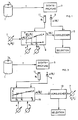
- FIG. 1 A first variant of the proposed method or the corresponding device is shown in FIG. 1 using a block diagram.
- a container 1 to be tested for density is subjected to a test pressure with regard to its surroundings Po.
- the container is then fed to a density test station 3 of a known type over an indefinite period of time T.
- the result of the density test at the time is a pressure variable p at temperature 8 measured with a sensor arrangement 5, in the time period of the density test, ie at time t.
- the pressure variable p which is measured in the density test, is, for example, the internal container pressure still prevailing after the time T has elapsed, both based on the ambient pressure, or if the container 1 is introduced into an autoclave during the density test, p is, for example, the then pressure in the autoclave.
- the technique used to carry out the density test, ie which pressure variable p is observed, is immaterial in the context of the present invention. It is essential that the pressure test p (6 1 ) is available directly or indirectly as a result of the density test.
- the measured pressure variable p (6 1 ) as a measure of the leakage must now be compared with a corresponding, predetermined pressure variable PG , i.e. it must be determined whether the measured pressure variable is larger or smaller than said limit value in order to decide whether the container can be described as tight or leaking.
- the limit pressure variable p G based on a temperature 8 2 at which the limit pressure variable PG has been specified, deviates.
- the density test temperature ⁇ 1 measured with a temperature sensor 11 is also fed to the correction unit 9.
- the latter basically works as a function generator and takes into account the linear approximation, at least in the first approximation Dependence between pressure p and temperature 8, with constant volume.
- the temperature ⁇ 1 in the time period t of the density test is again measured, and the measured pressure p is measured on a correction unit 15, taking into account the linear dependence between pressure and temperature at constant volume at least in the first approximation ; measured at the temperature ⁇ 1 , corrected to the previously known temperature 0 2 at which the limit pressure variable p G was specified on the specification unit 7.
- the correction units 9 and 15 can be implemented very simply, for example, in an analog design.
- FIG. 3 shows a simple circuit for realizing the correction unit 9.
- a signal corresponding to temperature 8 during the density test is fed to a first amplifier 15, with gain 1, from which the difference between this signal and a predetermined signal corresponding to temperature 6 2 is formed.
- the latter corresponds to the temperature at which the limit pressure variable p G was specified.
- the input of a further amplifier 17 is fed with the output signal corresponding to this temperature difference ⁇ 2 ⁇ 1 , the gain of which is set in accordance with the characteristic slope a.
- a possible structure of the correction unit 15 is shown in FIG. 4 analogously to FIG.
- a difference signal corresponding to the difference in temperature 8, in the density test and in temperature 8 2 , at which the limit pressure variable P G is predetermined, is formed on a first amplifier 19.
- it has a gain of 1 and a value corresponding to the temperature 8 2 is input to it.
- the output signal corresponding to this temperature difference ( ⁇ 2 ⁇ 1 ) is fed to a further amplifier circuit 21, the gain of which corresponds to the characteristic slope a.
- the "offset" signal of the amplifier circuit 21 is correspondingly signaled by the output of the pressure sensor 5 from FIG the measured pressure variable p (8 1 ).
- FIG. 5 shows a method that differs from the method shown in principle with reference to FIGS. 1 and 2.
- the temperature ⁇ 1 is measured at the moment t, the density test or in a time period before or after the density test, which is irrelevant with regard to the rapidity of thermal changes in the container.
- the aim should often be to separate the temperature measurement and the density test from time to place. If this is done, the temperature measurement on the container does not give the temperature that prevails during the density test of the container. Taking into account the time period between the temperature measurement and the density test, the temperature of the container at the beginning or at the end of this period must be used to infer the container temperature at the end or at the beginning of this time period, ie during the density test.
- the procedure adopted for this is shown in FIG. 5.
- the container 1 is again subjected to a test pressure quantity Po.
- the container temperature ⁇ B (t 2 ) is measured at a time t 2 using a temperature measuring device 31, based on the starting temperature ⁇ a .
- the thermal behavior of the container is identified or calculated at an identification unit 33, ie in particular its thermal time constant L TH .
- input variables I are to be entered in the identification unit 33 in a manner to be described. If the thermal behavior is given by the thermal time constant ⁇ TH , this variable is entered into a simulation unit 35 together with the measured container temperature ⁇ B (t 2 ).
- the simulation unit 35 forms the electrical simulation of the thermal container behavior, ie the function:
- the time of the temperature measurement t 2 is before the time t, the density test.
- the simulation can be accomplished by realizing a function falling exponentially with the thermal time constant ⁇ TH , which is excited with the initial value corresponding to ⁇ B (t 2 ) or ⁇ B ) (t 2 ) ⁇ u .
- the temperature value ⁇ B (t 1 ) corresponding to the container temperature during the density test at time t is determined by sampling or querying the output signal of the simulation unit 35 at the time of the density test t. This is implemented by the scanning unit 37, which, triggered by a sensor 39 that detects the density test taking place, then queries the output of the simulation unit 35. A signal correspondingly appears at the output of the scanning unit 37:
- the container temperature ⁇ B (t 1 ) is thus determined from a previous temperature measurement at time t 2 during the subsequent density test.
- This signal which corresponds to the temperature, is used in analogy to the explanations for FIG. 1 or FIG. 2, shown in FIG. 5 in analogy to FIG. 1, for the correction unit 9, at the output of which the correction unit corresponding to the temperature difference of the container temperature ⁇ B (t 1 ) with density test and the temperature (82), with the limit pressure variable specification corrected limit pressure variable P G ( ⁇ B (t 1 )) appears.
- This value is in turn fed to the comparison unit 13, together with the measured pressure variable p ( ⁇ B (t 1 )) relevant for the density test, the result of the comparison leads to a selection as to whether the tested container meets the density requirements or not.
- the quantities defining the thermal time constant TTH must be known, ie heat transfer coefficient a ', specific heat cp, dimension L of the container.
- These parameters of the container 1 and possibly its filling medium, which determine the time constant are input into the identification unit 33 a , which is now designed as a computing unit - inputs I of FIG. 5 - which determine the thermal time constant TTH therefrom. As shown in FIG. 5, this is in turn fed to the simulation unit 35.
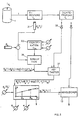
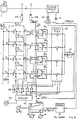
- FIG. 8 shows in a simple, analogous manner how a "one line" identification and simulation can be carried out for each container to be tested. It should be taken into account that the thermal time constants ⁇ TH differ only to a limited extent from container to container or even from container type to container type.
- two measurements are carried out here during the temperature measurement, be it with one and the same detector by successive scanning or by two staggered sensors attached along a movement path of a container 1 to be tested.
- the container 1 does not pass a first temperature sensor arrangement 31a on its path of travel after it has been subjected to the test pressure P o .
- the output signal of this measuring arrangement 31 a is applied to an identification and simulation unit 33, 35.
- the latter comprises a plurality of channels 1 to 4 etc. between inputs E, and outputs A 1 , E2 and A 2 etc.
- the output of the arrangement 31 a is at the point in time at which the container 1 is measured on the inputs E of the identification - and simulation unit 33, 35 connected.
- a switch Sa schematically represents that the output of the measuring arrangement 31 a is switched to said inputs E at time t a .
- the channels each have a function generator. As shown, the latter are extremely simple and each include, among other things, a network with high-pass characteristics, for example, RC elements, as shown. Each of the channels or the function generators assigned to them are permanently tuned to staggered time constants T ,, T2 etc.
- the container 1 Upon application of the output signal of the arrangement 31a to all channels corresponding to decreasing exponential functions with the channel-specific time constant T and the initial value corresponding to the output signal of the arrangement appear to the channel outputs A function curves 31 a at the time t a.
- the container 1 runs past a second temperature measuring arrangement 31 b , the output signal of which, as shown schematically by the switch S b , then to a number of comparators 35 1 , 35 2 , etc. is switched on, with each of the comparators 35 being connected to the output signal of one of the channels at a second input.
- Each of the comparators 35 thus compares a signal corresponding to the container temperature at the time t b with a channel output signal at the same time. If, as mentioned, the time constants of the channels T are successively staggered, for example Tl ⁇ T2 ⁇ T3 ⁇ T4 etc., the channel output signals have accordingly dropped to different extents. Thus, the comparison will indicate the comparators which channel output value the output of the temperature measuring assembly 31 b most closely corresponds. When checking all the comparator outputs, a pair of comparators will be found whose output signals are at different polarities. In the example shown, this is the case between the comparators 35 2 and 35 3 in that their output signal is indicated by * in the comparator characteristics shown.
- the interrogation of the comparator output signals takes place by means of a multiplexer unit 37. Clocked by a clock generator 39, the multiplexer unit 37 sequentially switches one comparator output after the other to a monostable unit 41. If a polarity change between two sequentially connected comparator outputs is detected, this results in the output of the multiplexer unit 37 a signal edge through which the monostable unit 41 is triggered and emits an output pulse.
- the clock pulses of the generator 39 are applied to a counter unit 43, which counts the pulses and thus identifies which of the comparator outputs is switched through by the multiplexer unit 37. If the aforementioned pulse appears at the output of the monostable unit 41, the counter 43 is (not shown) stopped.
- the channels are each assigned a count on counter 43.
- the outputs of the identification and simulation unit 33, 35, A are connected to the associated comparators 35 via changeover switches S u .
- the correction unit 9 is corrected at 8 2 predetermined limit pressure variable p G according to FIG. 1 to the relevant container temperature value t, the corrected limit pressure variable P G ( ⁇ B (t 3 ) ), as already described, together with the measured, pressure-relevant pressure variable p ( ⁇ B (t 3 )) from sensor 5, is fed to the comparison unit 13.
- the thermal behavior of the container is identified and simulated.
- the identification can also be carried out by measuring the container temperature at two times in accordance with t a and t b , and the identification can be carried out by relating the measured temperature values, such as by forming the quotient, from which the time constant results. If the time constant TTH is given, then the simulation is carried out by emulating an exponential function with an excitation corresponding to the measured values and the decay behavior corresponding to the time constant found.
- the simulated time function is queried at the point in time relevant for the density test in order to determine the container temperature during the density exercise.
- the pressure quantities are not measured directly, but indirectly by measuring physical quantities that depend on the pressure in a known manner, the corrections can also be made to the actually measured quantities, taking into account their dependence on the pressure or the temperature.
- the latter are carried out over predetermined time periods and the average temperature over these time periods is further processed as a relevant measured value.
- This can be done in known way by integrating the temperature output signals of the corresponding arrangements over a predetermined integration time, such as by an analog integrator or by relatively high-frequency sampling of the temperature output signals and subsequent digital averaging over a predetermined number of sampled signal values.
- Another problem with the temperature measurement is that it is difficult to carry out a measurement that is relevant for the temperature state of the containers, taking into account that the container temperature does not have to be the same at different container locations. This is taken into account by the fact that several temperature sensors simultaneously scan the temperature of a container and the mean value of the temperature values of all sensors is determined as the relevant container temperature value. The effort to be done for this, in particular by providing several temperature sensors, is relatively large. It must be taken into account that in most applications, the containers to be tested are not stationary with respect to a reference system with the measuring arrangements, but rather pass by at a relatively high speed on a path along which the temperature sensors are to be arranged during continuous production. A preferred arrangement of a temperature sensor, such as a pyroelectric detector, is shown in FIG.
- Containers 61 that are not yet closed run along a movement path X at the speed v.
- a pyroelectric detector 63 is fixed in the area of the container movement path X in such a way that the container openings 65 run past it. It has now been found that the thermal radiation in the interior of the container 61 is representative of the mean value of the temperature distribution along the entire container. The temperature is thus measured when a respective container 61 with its opening 65 lies in the range of the sensitivity characteristic of the pyroelectric detector 63. When this is the case can be detected by a separate position detector.
- the output signal of the detector 63 is first switched to a comparator unit 65, which is given a threshold value k o , the latter being selected such that the output signal of the detector 63 only exceeds it when an opening 65 enters its sensitivity characteristic.
- a switch S 63 is closed, for example via a monostable unit 67 or via a bistable, which is reset when the threshold value k o is fallen below again, which then switches on the output signal of the detector 63 as representative of the respective container temperature, to the devices shown in FIGS. 1 to 8 and connected downstream of the temperature measuring arrangements.
- this principle can be used, such as in the determination of relevant averaged body temperatures, as shown schematically in FIG. 10.
- a temperature relevant to its temperature state or its thermal energy content is to be measured on a body 70, with the temperature distribution in the body 70 being three-dimensionally unbalanced in the general case, an indentation 72 is worked into the body and the heat radiation S TH from that, a black one Indentation 72, which acts like a body, is measured with a detector 74, such as with a pyroelectric detector which is attached in the immediate region of the recess 72. This often eliminates the need for a very complex internal measurement of the temperature on such bodies.
Landscapes
- Physics & Mathematics (AREA)
- General Physics & Mathematics (AREA)
- Examining Or Testing Airtightness (AREA)
- Investigating Or Analyzing Materials Using Thermal Means (AREA)
- Small-Scale Networks (AREA)
- Supplying Of Containers To The Packaging Station (AREA)
- Measuring Fluid Pressure (AREA)
- Cookers (AREA)
- Measuring Temperature Or Quantity Of Heat (AREA)
Claims (22)
Priority Applications (2)
| Application Number | Priority Date | Filing Date | Title |
|---|---|---|---|
| EP89110862A EP0337510B1 (fr) | 1985-04-12 | 1986-04-09 | Procédé et dispositif de mesure de la chaleur d'un récipient ouvert ainsi qu'utilisation du procédé respectivement du dispositif pour des corps de boîtes ouvertes |
| AT86901769T ATE55012T1 (de) | 1985-04-12 | 1986-04-09 | Verfahren zur dichtepruefung von behaeltnissen sowie dichtepruefeinrichtung hierzu. |
Applications Claiming Priority (2)
| Application Number | Priority Date | Filing Date | Title |
|---|---|---|---|
| CH157785 | 1985-04-12 | ||
| CH1577/85 | 1985-04-12 |
Related Child Applications (1)
| Application Number | Title | Priority Date | Filing Date |
|---|---|---|---|
| EP89110862.3 Division-Into | 1989-06-15 |
Publications (2)
| Publication Number | Publication Date |
|---|---|
| EP0217833A1 EP0217833A1 (fr) | 1987-04-15 |
| EP0217833B1 true EP0217833B1 (fr) | 1990-07-25 |
Family
ID=4213666
Family Applications (1)
| Application Number | Title | Priority Date | Filing Date |
|---|---|---|---|
| EP86901769A Expired - Lifetime EP0217833B1 (fr) | 1985-04-12 | 1986-04-09 | Procede de controle de l'etancheite de receptacles ainsi qu installation de controle de l'etancheite pour sa mise en oeuvre |
Country Status (8)
| Country | Link |
|---|---|
| US (2) | US4896530A (fr) |
| EP (1) | EP0217833B1 (fr) |
| AT (1) | ATE118091T1 (fr) |
| CA (2) | CA1288972C (fr) |
| DE (2) | DE3672938D1 (fr) |
| ES (2) | ES8705972A1 (fr) |
| PT (1) | PT82369B (fr) |
| WO (1) | WO1986006166A2 (fr) |
Cited By (1)
| Publication number | Priority date | Publication date | Assignee | Title |
|---|---|---|---|---|
| DE102004039210B4 (de) * | 2004-08-12 | 2007-04-05 | Rudolf Wild Gmbh & Co. Kg | Verfahren zur Bewertung der Produkthaltbarkeit in einem Packmittel |
Families Citing this family (23)
| Publication number | Priority date | Publication date | Assignee | Title |
|---|---|---|---|---|
| GB8707231D0 (en) * | 1987-03-26 | 1987-04-29 | Analytical Instr Ltd | Temperature compensation in pressure leak detection |
| US5065350A (en) * | 1990-03-14 | 1991-11-12 | William L. Sweet | Method and apparatus for leak testing |
| US6662634B2 (en) * | 1994-06-15 | 2003-12-16 | Martin Lehmann | Method for testing containers, use of the method, and a testing device |
| ES2088350B1 (es) * | 1993-08-12 | 1999-01-01 | Rafibra S L | Procedimiento para el control de estanquidad en depositos |
| US5541520A (en) * | 1994-10-31 | 1996-07-30 | International Business Machines Corporation | Filtering for electronic module test |
| US5847264A (en) * | 1997-03-31 | 1998-12-08 | Roper Holdings, Inc. | Leak tester with flexible equation capabilities |
| DE19834332B4 (de) * | 1998-07-30 | 2005-06-02 | Robert Bosch Gmbh | Verfahren zur Prüfung der Funktionsfähigkeit eines Behältnisses |
| US6308556B1 (en) | 1999-12-17 | 2001-10-30 | Atc, Inc. | Method and apparatus of nondestructive testing a sealed product for leaks |
| US6584828B2 (en) | 1999-12-17 | 2003-07-01 | Atc, Inc. | Method and apparatus of nondestructive testing a sealed product for leaks |
| FR2803034A1 (fr) * | 1999-12-28 | 2001-06-29 | Gerard Fontan | Procede de verification de l'etancheite d'une caverne |
| US6412334B1 (en) * | 2000-02-07 | 2002-07-02 | Steris Inc. | Leak detector for endoscopes |
| US6408682B2 (en) | 2000-02-07 | 2002-06-25 | Steris Inc. | Leak detection method for endoscopes |
| GB0021435D0 (en) * | 2000-08-31 | 2000-10-18 | Safe Group The Ltd | A method of testing the pressure integrity of a rank |
| US7024919B2 (en) * | 2001-11-27 | 2006-04-11 | Aim Tech Co., Ltd. | Pressure measuring method and device |
| JP2005211757A (ja) * | 2004-01-28 | 2005-08-11 | National Institutes Of Natural Sciences | 水素同位体の分離方法、及び水素同位体の分離装置 |
| US20090139911A1 (en) * | 2007-11-30 | 2009-06-04 | Nova Chemicals Inc. | Method of detecting defective containers |
| DE102009040397A1 (de) * | 2009-09-07 | 2011-03-17 | Siemens Aktiengesellschaft | Diagnosesystem für ein Ventil |
| KR101512298B1 (ko) * | 2013-08-07 | 2015-04-15 | 강성일 | 누출 검사가 용이한 포장용 밀폐용기 및 이를 이용한 누출 검사방법과 검사장치 |
| JP2019158755A (ja) * | 2018-03-15 | 2019-09-19 | サーモス株式会社 | 液体容器及び管理システム |
| CN109855811A (zh) * | 2019-03-14 | 2019-06-07 | 中信戴卡股份有限公司 | 一种漏孔漏率检测装置及方法 |
| US11567479B2 (en) | 2020-11-16 | 2023-01-31 | Stellar Idea Labs | Early warning system for food safety violation and method thereof |
| CN117795303A (zh) * | 2021-08-18 | 2024-03-29 | 三菱电机株式会社 | 气密试验装置和气密试验方法 |
| CN119245933B (zh) * | 2024-09-27 | 2025-09-30 | 上海市特种设备监督检验技术研究院 | 一种基于热成像技术的气体泄漏检测方法、装置及设备 |
Family Cites Families (23)
| Publication number | Priority date | Publication date | Assignee | Title |
|---|---|---|---|---|
| DE137277C (fr) * | ||||
| US3056106A (en) * | 1958-07-14 | 1962-09-25 | Gamewell Co | Infrared detectors |
| US3065324A (en) * | 1960-09-19 | 1962-11-20 | Lindberg Eng Co | Control system for billet heaters |
| DE1573264A1 (de) * | 1965-06-14 | 1970-09-17 | Mahlo Heinz Dr Ing | Verfahren zur beruehrungslosen Temperaturmessung von teilweise durchlaessigem,flaechenhaftem Gut und Vorrichtung zur Durchfuehrung des Verfahrens |
| US3708680A (en) * | 1968-06-04 | 1973-01-02 | Automatic Sprinkler Corp | Container inspection apparatus with plural detectors and rotating projection system |
| US3579775A (en) * | 1969-04-03 | 1971-05-25 | Gen Electric | Tool surface temperature measuring apparatus |
| US3742191A (en) * | 1969-07-15 | 1973-06-26 | Irtronics Inc | Infrared temperature sensor and control for use with heated, moving bodies |
| US3653263A (en) * | 1969-07-15 | 1972-04-04 | Irtronics Inc | Infrared temperature sensor and control for use with heated, moving bodies |
| US3596519A (en) * | 1970-01-21 | 1971-08-03 | Molecular Research Inc | Hot spot detector system |
| US3800586A (en) * | 1972-04-24 | 1974-04-02 | Uson Corp | Leak testing apparatus |
| US3968368A (en) * | 1975-03-10 | 1976-07-06 | Owens-Illinois, Inc. | Inspection apparatus and method for hot glass containers |
| US3987664A (en) * | 1975-12-16 | 1976-10-26 | Applied Fluidics, Inc. | Dry-testing system for detecting leaks in containers |
| DE2829154A1 (de) * | 1978-07-03 | 1980-01-17 | Bbc Brown Boveri & Cie | Einrichtung zur temperaturmessung an insbesondere elektrischen maschinen, bauelementen o.dgl. |
| DE3023211A1 (de) * | 1979-06-28 | 1981-01-22 | Ti Fords Ltd | Verfahren und vorrichtung zur ermittlung einer waesserigen fluessigkeit in flaschen und behaeltern |
| US4272985A (en) * | 1979-12-03 | 1981-06-16 | Uson Corporation | Method of and apparatus for compensating for temperature in leak testing |
| DE3106981C2 (de) * | 1981-02-25 | 1984-07-19 | J.W. Froehlich Maschinenfabrik GmbH, 7022 Leinfelden-Echterdingen | Vorrichtung zum Prüfen von Bauteilen auf Dichtheit |
| DE3219409C2 (de) * | 1982-05-19 | 1984-10-11 | Schweizerische Aluminium Ag, Chippis | Verfahren zur Bestimmung der Oxidationsgeschwindigkeit an der Oberfläche einer Metallschmelze |
| JPS59206737A (ja) * | 1983-05-11 | 1984-11-22 | Cosmo Keiki:Kk | 温度補償機能を有する漏洩検査装置 |
| US4551627A (en) * | 1983-08-01 | 1985-11-05 | Kirin Beer Kabushiki Kaisha | Methods and apparatus for detecting residual liquid in containers |
| US4640627A (en) * | 1983-08-26 | 1987-02-03 | The Perkin-Elmer Corporation | Apparatus for monitoring a plasma torch |
| US4532795A (en) * | 1984-04-23 | 1985-08-06 | Semyon Brayman | Method of temperature compensating leak rate testing |
| US4625545A (en) * | 1985-04-05 | 1986-12-02 | Testrite, Inc. | Method and apparatus for detecting leaks |
| US4788427A (en) * | 1986-09-04 | 1988-11-29 | Leroy Pierre L | Fertilization detection |
-
1986
- 1986-04-09 DE DE8686901769T patent/DE3672938D1/de not_active Expired - Lifetime
- 1986-04-09 AT AT89110862T patent/ATE118091T1/de not_active IP Right Cessation
- 1986-04-09 DE DE3650224T patent/DE3650224D1/de not_active Expired - Fee Related
- 1986-04-09 US US07/006,554 patent/US4896530A/en not_active Expired - Fee Related
- 1986-04-09 EP EP86901769A patent/EP0217833B1/fr not_active Expired - Lifetime
- 1986-04-09 WO PCT/CH1986/000043 patent/WO1986006166A2/fr not_active Ceased
- 1986-04-11 PT PT82369A patent/PT82369B/pt not_active IP Right Cessation
- 1986-04-11 ES ES553929A patent/ES8705972A1/es not_active Expired
- 1986-04-14 CA CA000506565A patent/CA1288972C/fr not_active Expired - Lifetime
-
1987
- 1987-03-02 ES ES557433A patent/ES8802630A1/es not_active Expired
-
1989
- 1989-04-21 US US07/341,485 patent/US4989990A/en not_active Expired - Fee Related
-
1990
- 1990-12-10 CA CA000615952A patent/CA1300396C/fr not_active Expired - Lifetime
Cited By (2)
| Publication number | Priority date | Publication date | Assignee | Title |
|---|---|---|---|---|
| DE102004039210B4 (de) * | 2004-08-12 | 2007-04-05 | Rudolf Wild Gmbh & Co. Kg | Verfahren zur Bewertung der Produkthaltbarkeit in einem Packmittel |
| DE102004039210C5 (de) * | 2004-08-12 | 2012-11-15 | Rudolf Wild Gmbh & Co. Kg | Verfahren zur Bewertung der Produkthaltbarkeit in einem Packmittel |
Also Published As
| Publication number | Publication date |
|---|---|
| ES8802630A1 (es) | 1988-10-16 |
| ES557433A0 (es) | 1988-10-16 |
| US4896530A (en) | 1990-01-30 |
| EP0217833A1 (fr) | 1987-04-15 |
| PT82369B (pt) | 1992-07-31 |
| US4989990A (en) | 1991-02-05 |
| ATE118091T1 (de) | 1995-02-15 |
| ES8705972A1 (es) | 1987-06-01 |
| DE3672938D1 (de) | 1990-08-30 |
| CA1288972C (fr) | 1991-09-17 |
| WO1986006166A3 (fr) | 1986-11-20 |
| WO1986006166A2 (fr) | 1986-10-23 |
| ES553929A0 (es) | 1987-06-01 |
| DE3650224D1 (de) | 1995-03-16 |
| PT82369A (en) | 1986-05-01 |
| CA1300396C (fr) | 1992-05-12 |
Similar Documents
| Publication | Publication Date | Title |
|---|---|---|
| EP0217833B1 (fr) | Procede de controle de l'etancheite de receptacles ainsi qu installation de controle de l'etancheite pour sa mise en oeuvre | |
| DE69127144T2 (de) | Volumentest einer Plastikflasche in einer Produktionslinie | |
| EP0619015B1 (fr) | Procede pour le controle d'un recipient, dispositif de controle, utilisation | |
| EP3198251B1 (fr) | Dispositif et procédé d'étalonnage une chambre à membrane pour la détection de fuite | |
| EP3394588B1 (fr) | Mesure approximative de fuite d'un échantillon incompressible dans une chambre à film | |
| DE19546182A1 (de) | Verfahren und Vorrichtung zur verbesserten Fluß- und Druck-Messung und -Steuerung | |
| EP0029091A2 (fr) | Dispositif de surveillance électrique du niveau d'un liquide dans un récipient | |
| DE102013007631A1 (de) | Verfahren und Vorrichtung zur Bestimmung einer Kerntemperatur eines Körpers | |
| DE102017204102A1 (de) | Verfahren zum Prüfen eines Behälters auf Dichtheit | |
| EP0786654A2 (fr) | Système d'essai d'étanchéité pour des récipients fermés | |
| DE10018493C1 (de) | Vorrichtung zur dynamischen Kalibrierung piezoelektrischer Druckaufnehmer | |
| DE19513199A1 (de) | Verfahren und Vorrichtung zur Dichtigkeitsprüfung von Gehäusen | |
| DE112004002001T5 (de) | Kalibrierung und Validierung für einen Leckdetektor | |
| DE69304739T2 (de) | Gerät zum Nachweis von Teilchen | |
| DE3133421A1 (de) | Einrichtung zum elektrischen ueberwachen des niveaus einer in einem behaelter enthaltenen fluessigkeit | |
| DD206176A3 (de) | Verfahren und schaltungsanordnung zur temperaturmessung | |
| DE19805236C2 (de) | Verfahren und Vorrichtung zur Ermittlung des Volumens eines keramischen Probenkörpers | |
| DE2835162A1 (de) | Verfahren zur ueberpruefung des gasdruckes in einem kernbrennstab | |
| DE3219499A1 (de) | Verfahren zum pneumatischen messen des volumens eines hohlraumes oder der volumina von mehreren hohlraeumen an einem werkstueck, insbesondere der brennraumvolumina eines zylinderkopfes | |
| DE4308324C1 (de) | Verfahren zur kontinuierlichen Inspektion von Kunststoffflaschen | |
| DE4412762C2 (de) | Verfahren und Einrichtung zur Prüfung der Wasserdichtigkeit von Uhrengehäusen | |
| DE3106981C2 (de) | Vorrichtung zum Prüfen von Bauteilen auf Dichtheit | |
| DE102004036133B4 (de) | Verfahren und Vorrichtungen zur Ermittlung mindestens eines Volumens | |
| DE4315336A1 (de) | Verfahren und Einrichtung zur Messung und Korrektur von Prozeßvariablen | |
| EP2177889A1 (fr) | Procédé et dispositif pour un contrôle d'étanchéité |
Legal Events
| Date | Code | Title | Description |
|---|---|---|---|
| PUAI | Public reference made under article 153(3) epc to a published international application that has entered the european phase |
Free format text: ORIGINAL CODE: 0009012 |
|
| 17P | Request for examination filed |
Effective date: 19861121 |
|
| AK | Designated contracting states |
Kind code of ref document: A1 Designated state(s): AT BE CH DE FR GB IT LI LU NL SE |
|
| 17Q | First examination report despatched |
Effective date: 19880329 |
|
| ITF | It: translation for a ep patent filed | ||
| GRAA | (expected) grant |
Free format text: ORIGINAL CODE: 0009210 |
|
| AK | Designated contracting states |
Kind code of ref document: B1 Designated state(s): AT BE CH DE FR GB IT LI LU NL SE |
|
| REF | Corresponds to: |
Ref document number: 55012 Country of ref document: AT Date of ref document: 19900815 Kind code of ref document: T |
|
| XX | Miscellaneous (additional remarks) |
Free format text: TEILANMELDUNG 89110862.3 EINGEREICHT AM 09/04/86. |
|
| GBT | Gb: translation of ep patent filed (gb section 77(6)(a)/1977) | ||
| REF | Corresponds to: |
Ref document number: 3672938 Country of ref document: DE Date of ref document: 19900830 |
|
| ET | Fr: translation filed | ||
| PLBE | No opposition filed within time limit |
Free format text: ORIGINAL CODE: 0009261 |
|
| STAA | Information on the status of an ep patent application or granted ep patent |
Free format text: STATUS: NO OPPOSITION FILED WITHIN TIME LIMIT |
|
| 26N | No opposition filed | ||
| ITTA | It: last paid annual fee | ||
| PGFP | Annual fee paid to national office [announced via postgrant information from national office to epo] |
Ref country code: SE Payment date: 19940308 Year of fee payment: 9 |
|
| PGFP | Annual fee paid to national office [announced via postgrant information from national office to epo] |
Ref country code: BE Payment date: 19940309 Year of fee payment: 9 |
|
| PGFP | Annual fee paid to national office [announced via postgrant information from national office to epo] |
Ref country code: DE Payment date: 19940317 Year of fee payment: 9 |
|
| PGFP | Annual fee paid to national office [announced via postgrant information from national office to epo] |
Ref country code: GB Payment date: 19940330 Year of fee payment: 9 |
|
| PGFP | Annual fee paid to national office [announced via postgrant information from national office to epo] |
Ref country code: LU Payment date: 19940331 Year of fee payment: 9 |
|
| PGFP | Annual fee paid to national office [announced via postgrant information from national office to epo] |
Ref country code: AT Payment date: 19940426 Year of fee payment: 9 |
|
| PGFP | Annual fee paid to national office [announced via postgrant information from national office to epo] |
Ref country code: FR Payment date: 19940427 Year of fee payment: 9 |
|
| PGFP | Annual fee paid to national office [announced via postgrant information from national office to epo] |
Ref country code: NL Payment date: 19940430 Year of fee payment: 9 |
|
| EPTA | Lu: last paid annual fee | ||
| PGFP | Annual fee paid to national office [announced via postgrant information from national office to epo] |
Ref country code: CH Payment date: 19940624 Year of fee payment: 9 |
|
| EAL | Se: european patent in force in sweden |
Ref document number: 86901769.9 |
|
| PG25 | Lapsed in a contracting state [announced via postgrant information from national office to epo] |
Ref country code: LU Free format text: LAPSE BECAUSE OF NON-PAYMENT OF DUE FEES Effective date: 19950409 Ref country code: GB Effective date: 19950409 Ref country code: AT Effective date: 19950409 |
|
| PG25 | Lapsed in a contracting state [announced via postgrant information from national office to epo] |
Ref country code: SE Effective date: 19950410 |
|
| PG25 | Lapsed in a contracting state [announced via postgrant information from national office to epo] |
Ref country code: LI Effective date: 19950430 Ref country code: CH Effective date: 19950430 Ref country code: BE Effective date: 19950430 |
|
| BERE | Be: lapsed |
Owner name: LEHMANN MARTIN Effective date: 19950430 |
|
| PG25 | Lapsed in a contracting state [announced via postgrant information from national office to epo] |
Ref country code: NL Effective date: 19951101 |
|
| GBPC | Gb: european patent ceased through non-payment of renewal fee |
Effective date: 19950409 |
|
| REG | Reference to a national code |
Ref country code: CH Ref legal event code: PL |
|
| PG25 | Lapsed in a contracting state [announced via postgrant information from national office to epo] |
Ref country code: FR Effective date: 19951229 |
|
| NLV4 | Nl: lapsed or anulled due to non-payment of the annual fee |
Effective date: 19951101 |
|
| PG25 | Lapsed in a contracting state [announced via postgrant information from national office to epo] |
Ref country code: DE Effective date: 19960103 |
|
| EUG | Se: european patent has lapsed |
Ref document number: 86901769.9 |
|
| REG | Reference to a national code |
Ref country code: FR Ref legal event code: ST |
|
| PG25 | Lapsed in a contracting state [announced via postgrant information from national office to epo] |
Ref country code: IT Free format text: LAPSE BECAUSE OF NON-PAYMENT OF DUE FEES;WARNING: LAPSES OF ITALIAN PATENTS WITH EFFECTIVE DATE BEFORE 2007 MAY HAVE OCCURRED AT ANY TIME BEFORE 2007. THE CORRECT EFFECTIVE DATE MAY BE DIFFERENT FROM THE ONE RECORDED. Effective date: 20050409 |