EP0217868B1 - Ensemble d'interconnexion electrique - Google Patents
Ensemble d'interconnexion electrique Download PDFInfo
- Publication number
- EP0217868B1 EP0217868B1 EP86902228A EP86902228A EP0217868B1 EP 0217868 B1 EP0217868 B1 EP 0217868B1 EP 86902228 A EP86902228 A EP 86902228A EP 86902228 A EP86902228 A EP 86902228A EP 0217868 B1 EP0217868 B1 EP 0217868B1
- Authority
- EP
- European Patent Office
- Prior art keywords
- recesses
- electrical
- conductor
- cover means
- interconnection assembly
- Prior art date
- Legal status (The legal status is an assumption and is not a legal conclusion. Google has not performed a legal analysis and makes no representation as to the accuracy of the status listed.)
- Expired
Links
- 239000004020 conductor Substances 0.000 claims abstract description 58
- 238000000926 separation method Methods 0.000 abstract description 4
- 239000004743 Polypropylene Substances 0.000 description 4
- 230000000712 assembly Effects 0.000 description 4
- 238000000429 assembly Methods 0.000 description 4
- 239000011521 glass Substances 0.000 description 4
- -1 polypropylene Polymers 0.000 description 4
- 229920001155 polypropylene Polymers 0.000 description 4
- PXHVJJICTQNCMI-UHFFFAOYSA-N Nickel Chemical compound [Ni] PXHVJJICTQNCMI-UHFFFAOYSA-N 0.000 description 2
- 239000000463 material Substances 0.000 description 2
- 239000004033 plastic Substances 0.000 description 2
- 229910001369 Brass Inorganic materials 0.000 description 1
- QPLDLSVMHZLSFG-UHFFFAOYSA-N Copper oxide Chemical compound [Cu]=O QPLDLSVMHZLSFG-UHFFFAOYSA-N 0.000 description 1
- 239000005751 Copper oxide Substances 0.000 description 1
- DMFGNRRURHSENX-UHFFFAOYSA-N beryllium copper Chemical compound [Be].[Cu] DMFGNRRURHSENX-UHFFFAOYSA-N 0.000 description 1
- 239000010951 brass Substances 0.000 description 1
- 238000010276 construction Methods 0.000 description 1
- 229910000431 copper oxide Inorganic materials 0.000 description 1
- 230000000694 effects Effects 0.000 description 1
- PCHJSUWPFVWCPO-UHFFFAOYSA-N gold Chemical compound [Au] PCHJSUWPFVWCPO-UHFFFAOYSA-N 0.000 description 1
- 229910052737 gold Inorganic materials 0.000 description 1
- 239000010931 gold Substances 0.000 description 1
- 239000011810 insulating material Substances 0.000 description 1
- 238000009413 insulation Methods 0.000 description 1
- 238000004519 manufacturing process Methods 0.000 description 1
- 229910052759 nickel Inorganic materials 0.000 description 1
- 238000004806 packaging method and process Methods 0.000 description 1
- 201000009032 substance abuse Diseases 0.000 description 1
Images



Classifications
-
- H—ELECTRICITY
- H01—ELECTRIC ELEMENTS
- H01R—ELECTRICALLY-CONDUCTIVE CONNECTIONS; STRUCTURAL ASSOCIATIONS OF A PLURALITY OF MUTUALLY-INSULATED ELECTRICAL CONNECTING ELEMENTS; COUPLING DEVICES; CURRENT COLLECTORS
- H01R13/00—Details of coupling devices of the kinds covered by groups H01R12/70 or H01R24/00 - H01R33/00
- H01R13/73—Means for mounting coupling parts to apparatus or structures, e.g. to a wall
Definitions
- This invention relates to electrical interconnection, and more particularly relates to a high voltage interconnection assembly especially suitable for applying large operating voltages to traveling-wave tubes and similar electrical utilization devices.
- Traveling-wave tubes generally operate at high voltage levels, such as five kilovolts and greater, and it is necessary to connect such tubes to a high voltage source of power, often in field environments.
- a problem encountered with many conventional interconnect assemblies used for connecting a high voltage power supply to a traveling-wave tube is the fact that leads frequently are broken during packaging or field assembly. When the leads are broken in a field environment, it is virtually impossible to repair them without returning the interconnect assembly to the factory.
- an object of the invention to provide an electrical interconnection assembly for connecting a traveling-wave tube to a high voltage power supply in a convenient and low cost manner.
- An electrical interconnection assembly includes an electrically insulating housing member having an outer surface and an inner surface and adapted for mounting on an electrical utilization device.
- Recesses in the outer surface receive a plurality of first electrical conductors from a power supply and are provided with a plurality of first connectors for electrically engaging respective first electrical conductors.
- Recesses in the inner surface receive a plurality of second electrical conductors from the electrical utilization device and are provided with a plurality of second connectors for electrically engaging respective second electrical conductors.
- Each second connector is electrically connected to a respective first connector.
- First and second electrically insulating covers are adapted to be releasably secured to the housing member to cover respective portions of the outer and inner housing member surfaces including the recesses therein.
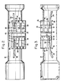
- Fig. 1 illustrates a traveling-wave tube 10 provided with an electrical interconnection assembly 12 according to the invention.
- a plurality of first inner electrical conductors 24 are designed to deliver relatively low voltages to a terminal block 26 at one end of the traveling-wave tube 10. These voltages typically maybe about 5 000 volts, 7 000 volts, and 9 000 volts, for example.
- a plurality of second inner electrical conductors 28 are connected to a terminal block 30 at the opposite end of the traveling-wave tube 10. The conductors 28 are designed to deliver a higher voltage, for example, 11 000 volts, to the tube 10.
- the interconnection assembly 12 comprises a housing member 32 of an inverted substantially U-shaped cross-section and sized to extend over the outer envelope of the magnetic focusing arrangement 14 of the traveling-wave tube 10.
- Housing member 32 may be of a plastic material such as glass-filled polypropylene. As a specific example for illustrative purposes, the material for the housing member 32 may be approximately 10 % glass and approximately 90 % polypropylene.
- Integrally formed with the housing member 32 on an upper surface thereof is a conductor mounting platform 34.
- the interior surface of the housing member 32 is integrally provided with a conductor mounting cavity 35 (Fig. 3).
- the mounting platform 34 is provided with a first plurality (three are shown) of neighboring conductor-receiving recesses 36 designed to receive relatively low voltage outer conductors 48 (Fig. 2).
- the mounting platform 34 is provided with a second plurality (four are shown) of neighboring conductor-receiving recesses 38 to receive higher voltage outer conductors 49 (Fig. 2).
- the mounting cavity 35 on the inner surface of the housing member 32 is similarly provided with three recesses 40 substantially aligned with the recesses 36 and designed to receive the conductors 24.
- another portion of inner surface of the housing member 32 is provided with an enlarged recessed area 41 for receiving the conductors 28.
- individual recesses could be formed, if desired, to receive each of the conductors 28.
- Separating adjacent recesses 36 on the outer surface of the housing member 32 are a pair of parallel longitudinally extending ridges 42 having a longitudinally extending groove 43 therebetween and designed to prevent electrical arcing or corona discharge between the recesses 36.
- Disposed between adjacent recesses 38 are longitudinally extending ridges 44 likewise designed to prevent corona discharge or arcing.
- a tranversely extending groove 45 is provided between the areas designed to receive these sets of conductors.
- Longitudinally extending ridges 46 are provided on the inner surface of the housing member 32 to preclude arcing between the inner conductors 24 in the respective recesses 40, while transversely extending ridge 47 is provided to preclude arcing between the inner conductors 28 and 24.
- each conductor 24, 28, 48 and 49 comprises an inner electrical wire 50 surrounded by an outer insulating layer or "sheath" 52.
- the end portions of the conductors 24, 28, 48 and 49 are stripped, i.e., the insulating layer 52 is removed to expose the wire 50.
- an electrically conductive terminal connector 54 having a pin- receiving hole 55 at one end may be crimped onto or otherwise secured to the exposed end of the wire 50.
- the terminal connector 54 may be of gold-plated, heat-treated beryllium-copper, for example, although some nickel may be included to prevent copper oxide from migrating from the connector 54 through the gold.
- Each of the recesses 36 and 38 have elevated head portions 56 at their inner ends for receiving the terminal connectors 54, and have sections of greater depth throughout the remainder of their length to receive the insulated portions 52 of the conductors 48 and 49.
- Each of the recesses 36 and 38 further define near their outer ends a pair of transversely disposed protruding bar portions 60.
- the protruding bar portions 60 are designed to engage the insulating portion 52 of conductor 48 or 49 and minimize any tendency for inadvertent pulling of a conductor 48 or 49 out of its associated recess or inadvertent separation of the terminal connectors 54 from the wires 50.
- the various recesses 40 and the enlarged recessed area 41 on the inner surface of the housing member 32 are similarly provided with elevated head potions 61 and 62, respectively, to receive terminal connectors 54 mounted on stripped ends of the electrical conductors 24 and 28 as described above with respect to conductors 48 and 49.
- Conductive pins 66 and 68 protrude from the head portions 56 of each of the recesses 36 and 38, respectively, while similar conductive pins 70 and 72 protude from the respective head portions 61 and 62 of the recesses 40 and 41, respectively.
- the pins 66, 68, 70 and 72 may be gold-plated brass, for example.
- conductive pins 66 and 70 may be integral with each other (as shown in Fig. 9) and extend through an aperture in the housing 32.
- conductive pins 68 and 72 may be integrally formed with one another. In any event, the pins 68 and 72 are electrically connected together, while the pins 66 and 70 are likewise electrically interconnected. All of the pins 66, 68, 70 and 72 are designed to snuggly but removably fit in the holes 55 in the terminal connectors 54.
- An electrical interconnection assembly includes an outer cover 80 (Fig. 1) and inner cover 82 (Fig. 7), both of a flexible insulating material such as plastic.
- the covers 80 and 82 may be of a glass-filled polypropylene consisting of approximately 20 % glass and approximately 80 % polypropylene.
- the inner cover 82 has a bent cross-section substantially conforming to the curvature of the inner surface of the housing member 32.
- the cover 82 is integrally formed with a pair of longitudinally projecting tabs 84 on each of its opposite ends.
- the tabs 84 are adapted to be engaged by abutments 86 integrally formed on the inner surface of the housing member 32
- the cover 82 can be bent slightly about its longitudinal axis and snap-fit into engaging relationship between the tabs 84 and the abutments 86.
- the inner cover 82 can be removed from this engaging relationship simply by prying it to move the tabs 84 out of engagement with the abutments 86.
- the cover 82 is shaped to contact the ends of the pins 70 and 72.
- the outer cover 80 is substantially arcuately shaped, as shown in Figs. 4 and 5, and defines on its inner surface three longitudinal recesses 88 (Fig. 8) which conform to and are disposed in registration with the recesses 36 in the mounting platform 34 when the cover 80 is snap-fit into position.
- longitudinal ridges 90 are integrally provided on the inner surface of the cover 80 and are adapted to fit in the respective grooves 43 in the platform 34.
- another region of the inner surface of the cover 80 is provided with four recesses 92 capable of being disposed in registration with the recesses 38 in the platform 34.
- Each of the recesses 92 are separated by ridges 94 which are aligned with the respective ridges 44 between the recesses 38 when the cover 80 is in place.
- the recesses 88 each define near their outer ends a pair of transversely disposed protruding bar portions 95 which are staggered along the length of the recesses 88 and 36 with respect to the bar portions 60 and cooperate therewith to grip the conductors 48 therebetween (Fig. 9).
- the outer ends of the recesses 92 are provided with a pair of staggered transverse protruding bar portions 96 which cooperate with the opposing bar portions 60 to grip the conductors 49 therebetween.
- the cover 80 is also provided with a transversely extending ridge 98 which is capable of fitting into transverse groove 45 in the platform 34.
- the ridge 98 aids in preventing arcing between the high and low voltage outer conductors residing in the recesses 92 and 88, respectively.
- the cover 80 further defines a pair of longitudinally extending grooves 102 near the respective transverse extremities of its inner surface.
- the grooves 102 are capable of engaging outwardly extending projections 104 on the mounting platform 34. In this way, the cover 80 can be snap-fit into position over the platform 34 and removed therefrom by merely prying one of its edges from the engaging projections 104.
- conductors 24 and 28 from the traveling-wave tube 10 are electrically connected to the pins 70 and 72 by press-fitting the pins 66 and 68 into the connector holes 55.
- Individual conductors 48 and 49 from the power supply are similarly connected to the pins 66 and 68, respectively.
- the respective covers 82 and 80 can be snap-fit into place on the inner and outer surfaces of the housing member 32. As this occurs, the bar portions 95 and 96 on the outer cover 80 will cooperate with the bar portions 60 to hold the outer conductors 48 and 49 in place.
- an electrical interconnection assembly is designed to handle abuses that may be encountered in field operations and enables simple and reliable field replacement of the conductors 48 and 49. It is also designed to withstand relatively high and low service temperatures, as for example, from about -55° C to about +100°C. Furthermore, the assembly is highly reliable at normal service temperatures of about 70°C.
Landscapes
- Connector Housings Or Holding Contact Members (AREA)
- Coupling Device And Connection With Printed Circuit (AREA)
Abstract
Claims (7)
Applications Claiming Priority (2)
| Application Number | Priority Date | Filing Date | Title |
|---|---|---|---|
| US06/721,098 US4676578A (en) | 1985-04-08 | 1985-04-08 | Electrical interconnection assembly |
| US721098 | 1985-04-08 |
Publications (2)
| Publication Number | Publication Date |
|---|---|
| EP0217868A1 EP0217868A1 (fr) | 1987-04-15 |
| EP0217868B1 true EP0217868B1 (fr) | 1989-05-31 |
Family
ID=24896528
Family Applications (1)
| Application Number | Title | Priority Date | Filing Date |
|---|---|---|---|
| EP86902228A Expired EP0217868B1 (fr) | 1985-04-08 | 1986-03-24 | Ensemble d'interconnexion electrique |
Country Status (7)
| Country | Link |
|---|---|
| US (1) | US4676578A (fr) |
| EP (1) | EP0217868B1 (fr) |
| JP (1) | JPS62502083A (fr) |
| DE (1) | DE3663762D1 (fr) |
| IL (1) | IL78170A0 (fr) |
| NO (1) | NO169263C (fr) |
| WO (1) | WO1986006217A1 (fr) |
Families Citing this family (2)
| Publication number | Priority date | Publication date | Assignee | Title |
|---|---|---|---|---|
| JP6697627B1 (ja) * | 2019-11-28 | 2020-05-20 | 那須 正和 | 折巻植栽ユニット |
| JP6679131B1 (ja) * | 2019-11-28 | 2020-04-15 | 那須 正和 | 折巻収納ユニット |
Citations (4)
| Publication number | Priority date | Publication date | Assignee | Title |
|---|---|---|---|---|
| US3016512A (en) * | 1959-09-22 | 1962-01-09 | Bell Telephone Labor Inc | Connector assembly |
| US3753216A (en) * | 1971-10-14 | 1973-08-14 | Amp Inc | High voltage terminal strip |
| US4284316A (en) * | 1979-10-11 | 1981-08-18 | Cgee Alsthom | Terminal block |
| US4449777A (en) * | 1982-03-01 | 1984-05-22 | Minnesota Mining And Manufacturing Company | Drop wire connector |
Family Cites Families (2)
| Publication number | Priority date | Publication date | Assignee | Title |
|---|---|---|---|---|
| DE8009293U1 (de) * | 1980-04-03 | 1981-09-17 | Robert Bosch Gmbh, 7000 Stuttgart | Steckverbindung für Zündverteiler von Brennkraftmaschinen |
| US4410224A (en) * | 1981-08-24 | 1983-10-18 | Ico Rally Corporation | Interconnection device for multiple conductor cables |
-
1985
- 1985-04-08 US US06/721,098 patent/US4676578A/en not_active Expired - Lifetime
-
1986
- 1986-03-17 IL IL78170A patent/IL78170A0/xx not_active IP Right Cessation
- 1986-03-24 DE DE8686902228T patent/DE3663762D1/de not_active Expired
- 1986-03-24 JP JP61501786A patent/JPS62502083A/ja active Granted
- 1986-03-24 WO PCT/US1986/000590 patent/WO1986006217A1/fr not_active Ceased
- 1986-03-24 EP EP86902228A patent/EP0217868B1/fr not_active Expired
- 1986-11-19 NO NO864621A patent/NO169263C/no unknown
Patent Citations (4)
| Publication number | Priority date | Publication date | Assignee | Title |
|---|---|---|---|---|
| US3016512A (en) * | 1959-09-22 | 1962-01-09 | Bell Telephone Labor Inc | Connector assembly |
| US3753216A (en) * | 1971-10-14 | 1973-08-14 | Amp Inc | High voltage terminal strip |
| US4284316A (en) * | 1979-10-11 | 1981-08-18 | Cgee Alsthom | Terminal block |
| US4449777A (en) * | 1982-03-01 | 1984-05-22 | Minnesota Mining And Manufacturing Company | Drop wire connector |
Also Published As
| Publication number | Publication date |
|---|---|
| NO169263C (no) | 1992-05-27 |
| US4676578A (en) | 1987-06-30 |
| JPS62502083A (ja) | 1987-08-13 |
| JPH0254628B2 (fr) | 1990-11-22 |
| NO864621L (no) | 1986-11-19 |
| WO1986006217A1 (fr) | 1986-10-23 |
| EP0217868A1 (fr) | 1987-04-15 |
| IL78170A0 (en) | 1986-07-31 |
| NO169263B (no) | 1992-02-17 |
| DE3663762D1 (en) | 1989-07-06 |
Similar Documents
| Publication | Publication Date | Title |
|---|---|---|
| CN112219322B (zh) | 高电流插接连接器及其装配方法 | |
| US3850496A (en) | Connector block for hermetic motor compressor | |
| US3189863A (en) | Connector | |
| US6045374A (en) | Electrical wiring system | |
| US4390225A (en) | Fuse block assembly | |
| PL175151B1 (pl) | Zacisk szeregowy | |
| EP0386742A1 (fr) | Connecteur électrique avec contacts de culot de grandeur différente ayant des moyens pour éviter une connexion erronée | |
| JPH0227673A (ja) | モジュラジャック接続ブロック | |
| US3275765A (en) | Electrical connecting and switch device | |
| US3266007A (en) | High voltage terminal block | |
| EP0000434B1 (fr) | Bloc de connexion pour relier des fils avec deux parties applicables l'une sur l'autre et des barrettes de contact fendues | |
| US5545060A (en) | Clamping terminal unit | |
| US5013265A (en) | Connector for mating blade-shaped members | |
| US6053750A (en) | Plug bridge for an electric appliance plug | |
| HK1004785B (en) | Connector assembly | |
| US3860319A (en) | Boxless electrical component | |
| US3226669A (en) | Wire conductors in electrical connection fields | |
| EP0217868B1 (fr) | Ensemble d'interconnexion electrique | |
| JPS6297273A (ja) | 電気コネクタ | |
| US7534151B1 (en) | Electrical connection terminal | |
| US4458970A (en) | Electrical contact and connector using such contacts | |
| US4555588A (en) | Heat transfer device for electrical connector in insulating housing of high voltage splice or terminator | |
| EP0929127A1 (fr) | Ensemble de connexion | |
| US3391262A (en) | Multipurpose electrical connector for use with ac and/or dc receptacles | |
| US3300751A (en) | Multiple electrical connector |
Legal Events
| Date | Code | Title | Description |
|---|---|---|---|
| PUAI | Public reference made under article 153(3) epc to a published international application that has entered the european phase |
Free format text: ORIGINAL CODE: 0009012 |
|
| 17P | Request for examination filed |
Effective date: 19861031 |
|
| AK | Designated contracting states |
Kind code of ref document: A1 Designated state(s): DE FR GB IT NL |
|
| 17Q | First examination report despatched |
Effective date: 19880803 |
|
| GRAA | (expected) grant |
Free format text: ORIGINAL CODE: 0009210 |
|
| AK | Designated contracting states |
Kind code of ref document: B1 Designated state(s): DE FR GB IT NL |
|
| REF | Corresponds to: |
Ref document number: 3663762 Country of ref document: DE Date of ref document: 19890706 |
|
| ITF | It: translation for a ep patent filed | ||
| ET | Fr: translation filed | ||
| PLBE | No opposition filed within time limit |
Free format text: ORIGINAL CODE: 0009261 |
|
| STAA | Information on the status of an ep patent application or granted ep patent |
Free format text: STATUS: NO OPPOSITION FILED WITHIN TIME LIMIT |
|
| 26N | No opposition filed | ||
| ITTA | It: last paid annual fee | ||
| PGFP | Annual fee paid to national office [announced via postgrant information from national office to epo] |
Ref country code: NL Payment date: 19940331 Year of fee payment: 9 |
|
| PG25 | Lapsed in a contracting state [announced via postgrant information from national office to epo] |
Ref country code: NL Effective date: 19951001 |
|
| NLV4 | Nl: lapsed or anulled due to non-payment of the annual fee |
Effective date: 19951001 |
|
| REG | Reference to a national code |
Ref country code: GB Ref legal event code: 732E |
|
| REG | Reference to a national code |
Ref country code: GB Ref legal event code: IF02 |
|
| PGFP | Annual fee paid to national office [announced via postgrant information from national office to epo] |
Ref country code: FR Payment date: 20050211 Year of fee payment: 20 |
|
| PGFP | Annual fee paid to national office [announced via postgrant information from national office to epo] |
Ref country code: GB Payment date: 20050214 Year of fee payment: 20 |
|
| PGFP | Annual fee paid to national office [announced via postgrant information from national office to epo] |
Ref country code: DE Payment date: 20050216 Year of fee payment: 20 |
|
| PGFP | Annual fee paid to national office [announced via postgrant information from national office to epo] |
Ref country code: IT Payment date: 20050222 Year of fee payment: 20 |
|
| PG25 | Lapsed in a contracting state [announced via postgrant information from national office to epo] |
Ref country code: GB Free format text: LAPSE BECAUSE OF EXPIRATION OF PROTECTION Effective date: 20060323 |
|
| REG | Reference to a national code |
Ref country code: GB Ref legal event code: PE20 |