EP0217964A1 - Appareil medical a pompe - Google Patents
Appareil medical a pompe Download PDFInfo
- Publication number
- EP0217964A1 EP0217964A1 EP86902475A EP86902475A EP0217964A1 EP 0217964 A1 EP0217964 A1 EP 0217964A1 EP 86902475 A EP86902475 A EP 86902475A EP 86902475 A EP86902475 A EP 86902475A EP 0217964 A1 EP0217964 A1 EP 0217964A1
- Authority
- EP
- European Patent Office
- Prior art keywords
- artery
- signal
- time
- reconstructed
- blood flow
- Prior art date
- Legal status (The legal status is an assumption and is not a legal conclusion. Google has not performed a legal analysis and makes no representation as to the accuracy of the status listed.)
- Withdrawn
Links
- 210000001367 artery Anatomy 0.000 claims abstract description 51
- 230000017531 blood circulation Effects 0.000 claims abstract description 39
- 239000008280 blood Substances 0.000 claims abstract description 15
- 210000004369 blood Anatomy 0.000 claims abstract description 15
- 230000033001 locomotion Effects 0.000 claims description 18
- 230000010349 pulsation Effects 0.000 abstract 1
- 239000007788 liquid Substances 0.000 description 16
- 230000008859 change Effects 0.000 description 6
- 238000002347 injection Methods 0.000 description 6
- 239000007924 injection Substances 0.000 description 6
- 230000002159 abnormal effect Effects 0.000 description 5
- 238000007599 discharging Methods 0.000 description 5
- 238000006073 displacement reaction Methods 0.000 description 5
- 230000004044 response Effects 0.000 description 5
- 238000011144 upstream manufacturing Methods 0.000 description 4
- 210000004204 blood vessel Anatomy 0.000 description 3
- 230000003247 decreasing effect Effects 0.000 description 3
- 239000012530 fluid Substances 0.000 description 3
- 239000003921 oil Substances 0.000 description 3
- 230000000630 rising effect Effects 0.000 description 3
- 230000001360 synchronised effect Effects 0.000 description 3
- 241001465754 Metazoa Species 0.000 description 2
- 230000006835 compression Effects 0.000 description 2
- 238000007906 compression Methods 0.000 description 2
- 230000003111 delayed effect Effects 0.000 description 2
- 230000000694 effects Effects 0.000 description 2
- 230000010247 heart contraction Effects 0.000 description 2
- 230000001717 pathogenic effect Effects 0.000 description 2
- 230000002093 peripheral effect Effects 0.000 description 2
- 238000004393 prognosis Methods 0.000 description 2
- 229920002379 silicone rubber Polymers 0.000 description 2
- 230000002269 spontaneous effect Effects 0.000 description 2
- 206010003210 Arteriosclerosis Diseases 0.000 description 1
- XUIMIQQOPSSXEZ-UHFFFAOYSA-N Silicon Chemical compound [Si] XUIMIQQOPSSXEZ-UHFFFAOYSA-N 0.000 description 1
- FAPWRFPIFSIZLT-UHFFFAOYSA-M Sodium chloride Chemical compound [Na+].[Cl-] FAPWRFPIFSIZLT-UHFFFAOYSA-M 0.000 description 1
- 239000004809 Teflon Substances 0.000 description 1
- 229920006362 Teflon® Polymers 0.000 description 1
- 239000006096 absorbing agent Substances 0.000 description 1
- NIXOWILDQLNWCW-UHFFFAOYSA-N acrylic acid group Chemical group C(C=C)(=O)O NIXOWILDQLNWCW-UHFFFAOYSA-N 0.000 description 1
- 230000004913 activation Effects 0.000 description 1
- 230000001154 acute effect Effects 0.000 description 1
- 210000000702 aorta abdominal Anatomy 0.000 description 1
- 208000011775 arteriosclerosis disease Diseases 0.000 description 1
- 239000002473 artificial blood Substances 0.000 description 1
- 230000023555 blood coagulation Effects 0.000 description 1
- 239000003130 blood coagulation factor inhibitor Substances 0.000 description 1
- 230000000747 cardiac effect Effects 0.000 description 1
- 238000004891 communication Methods 0.000 description 1
- 239000000470 constituent Substances 0.000 description 1
- 230000008602 contraction Effects 0.000 description 1
- 230000009849 deactivation Effects 0.000 description 1
- 230000001934 delay Effects 0.000 description 1
- 230000001419 dependent effect Effects 0.000 description 1
- 238000011161 development Methods 0.000 description 1
- 201000010099 disease Diseases 0.000 description 1
- 208000037265 diseases, disorders, signs and symptoms Diseases 0.000 description 1
- 239000003814 drug Substances 0.000 description 1
- 229940079593 drug Drugs 0.000 description 1
- 238000005516 engineering process Methods 0.000 description 1
- 230000005284 excitation Effects 0.000 description 1
- 210000003414 extremity Anatomy 0.000 description 1
- 230000006870 function Effects 0.000 description 1
- 210000003692 ilium Anatomy 0.000 description 1
- 230000006872 improvement Effects 0.000 description 1
- 238000005259 measurement Methods 0.000 description 1
- 230000007246 mechanism Effects 0.000 description 1
- 239000012528 membrane Substances 0.000 description 1
- 230000004060 metabolic process Effects 0.000 description 1
- 238000000034 method Methods 0.000 description 1
- 238000012544 monitoring process Methods 0.000 description 1
- 210000003205 muscle Anatomy 0.000 description 1
- -1 polytetrafluoroethylene Polymers 0.000 description 1
- 229920001343 polytetrafluoroethylene Polymers 0.000 description 1
- 239000004810 polytetrafluoroethylene Substances 0.000 description 1
- 230000003449 preventive effect Effects 0.000 description 1
- 230000002040 relaxant effect Effects 0.000 description 1
- 239000011347 resin Substances 0.000 description 1
- 229920005989 resin Polymers 0.000 description 1
- 229910052710 silicon Inorganic materials 0.000 description 1
- 239000010703 silicon Substances 0.000 description 1
- 239000011780 sodium chloride Substances 0.000 description 1
- 239000007787 solid Substances 0.000 description 1
- 238000001356 surgical procedure Methods 0.000 description 1
- 238000012360 testing method Methods 0.000 description 1
- 230000001225 therapeutic effect Effects 0.000 description 1
- 210000000689 upper leg Anatomy 0.000 description 1
- 210000003462 vein Anatomy 0.000 description 1
- 230000002861 ventricular Effects 0.000 description 1
- XLYOFNOQVPJJNP-UHFFFAOYSA-N water Substances O XLYOFNOQVPJJNP-UHFFFAOYSA-N 0.000 description 1
Images








Classifications
-
- A—HUMAN NECESSITIES
- A61—MEDICAL OR VETERINARY SCIENCE; HYGIENE
- A61M—DEVICES FOR INTRODUCING MEDIA INTO, OR ONTO, THE BODY; DEVICES FOR TRANSDUCING BODY MEDIA OR FOR TAKING MEDIA FROM THE BODY; DEVICES FOR PRODUCING OR ENDING SLEEP OR STUPOR
- A61M1/00—Suction or pumping devices for medical purposes; Devices for carrying-off, for treatment of, or for carrying-over, body-liquids; Drainage systems
- A61M1/36—Other treatment of blood in a by-pass of the natural circulatory system, e.g. temperature adaptation, irradiation ; Extra-corporeal blood circuits
-
- A—HUMAN NECESSITIES
- A61—MEDICAL OR VETERINARY SCIENCE; HYGIENE
- A61M—DEVICES FOR INTRODUCING MEDIA INTO, OR ONTO, THE BODY; DEVICES FOR TRANSDUCING BODY MEDIA OR FOR TAKING MEDIA FROM THE BODY; DEVICES FOR PRODUCING OR ENDING SLEEP OR STUPOR
- A61M60/00—Blood pumps; Devices for mechanical circulatory actuation; Balloon pumps for circulatory assistance
- A61M60/10—Location thereof with respect to the patient's body
- A61M60/122—Implantable pumps or pumping devices, i.e. the blood being pumped inside the patient's body
- A61M60/126—Implantable pumps or pumping devices, i.e. the blood being pumped inside the patient's body implantable via, into, inside, in line, branching on, or around a blood vessel
-
- A—HUMAN NECESSITIES
- A61—MEDICAL OR VETERINARY SCIENCE; HYGIENE
- A61M—DEVICES FOR INTRODUCING MEDIA INTO, OR ONTO, THE BODY; DEVICES FOR TRANSDUCING BODY MEDIA OR FOR TAKING MEDIA FROM THE BODY; DEVICES FOR PRODUCING OR ENDING SLEEP OR STUPOR
- A61M60/00—Blood pumps; Devices for mechanical circulatory actuation; Balloon pumps for circulatory assistance
- A61M60/20—Type thereof
- A61M60/247—Positive displacement blood pumps
- A61M60/253—Positive displacement blood pumps including a displacement member directly acting on the blood
- A61M60/268—Positive displacement blood pumps including a displacement member directly acting on the blood the displacement member being flexible, e.g. membranes, diaphragms or bladders
- A61M60/274—Positive displacement blood pumps including a displacement member directly acting on the blood the displacement member being flexible, e.g. membranes, diaphragms or bladders the inlet and outlet being the same, e.g. para-aortic counter-pulsation blood pumps
-
- A—HUMAN NECESSITIES
- A61—MEDICAL OR VETERINARY SCIENCE; HYGIENE
- A61M—DEVICES FOR INTRODUCING MEDIA INTO, OR ONTO, THE BODY; DEVICES FOR TRANSDUCING BODY MEDIA OR FOR TAKING MEDIA FROM THE BODY; DEVICES FOR PRODUCING OR ENDING SLEEP OR STUPOR
- A61M60/00—Blood pumps; Devices for mechanical circulatory actuation; Balloon pumps for circulatory assistance
- A61M60/30—Medical purposes thereof other than the enhancement of the cardiac output
- A61M60/35—Medical purposes thereof other than the enhancement of the cardiac output for specific surgeries, e.g. for Fontan procedure
-
- A—HUMAN NECESSITIES
- A61—MEDICAL OR VETERINARY SCIENCE; HYGIENE
- A61M—DEVICES FOR INTRODUCING MEDIA INTO, OR ONTO, THE BODY; DEVICES FOR TRANSDUCING BODY MEDIA OR FOR TAKING MEDIA FROM THE BODY; DEVICES FOR PRODUCING OR ENDING SLEEP OR STUPOR
- A61M60/00—Blood pumps; Devices for mechanical circulatory actuation; Balloon pumps for circulatory assistance
- A61M60/40—Details relating to driving
- A61M60/424—Details relating to driving for positive displacement blood pumps
- A61M60/427—Details relating to driving for positive displacement blood pumps the force acting on the blood contacting member being hydraulic or pneumatic
- A61M60/43—Details relating to driving for positive displacement blood pumps the force acting on the blood contacting member being hydraulic or pneumatic using vacuum at the blood pump, e.g. to accelerate filling
-
- A—HUMAN NECESSITIES
- A61—MEDICAL OR VETERINARY SCIENCE; HYGIENE
- A61M—DEVICES FOR INTRODUCING MEDIA INTO, OR ONTO, THE BODY; DEVICES FOR TRANSDUCING BODY MEDIA OR FOR TAKING MEDIA FROM THE BODY; DEVICES FOR PRODUCING OR ENDING SLEEP OR STUPOR
- A61M60/00—Blood pumps; Devices for mechanical circulatory actuation; Balloon pumps for circulatory assistance
- A61M60/40—Details relating to driving
- A61M60/424—Details relating to driving for positive displacement blood pumps
- A61M60/427—Details relating to driving for positive displacement blood pumps the force acting on the blood contacting member being hydraulic or pneumatic
- A61M60/435—Details relating to driving for positive displacement blood pumps the force acting on the blood contacting member being hydraulic or pneumatic with diastole or systole switching by valve means located between the blood pump and the hydraulic or pneumatic energy source
-
- A—HUMAN NECESSITIES
- A61—MEDICAL OR VETERINARY SCIENCE; HYGIENE
- A61M—DEVICES FOR INTRODUCING MEDIA INTO, OR ONTO, THE BODY; DEVICES FOR TRANSDUCING BODY MEDIA OR FOR TAKING MEDIA FROM THE BODY; DEVICES FOR PRODUCING OR ENDING SLEEP OR STUPOR
- A61M60/00—Blood pumps; Devices for mechanical circulatory actuation; Balloon pumps for circulatory assistance
- A61M60/50—Details relating to control
- A61M60/508—Electronic control means, e.g. for feedback regulation
- A61M60/515—Regulation using real-time patient data
-
- A—HUMAN NECESSITIES
- A61—MEDICAL OR VETERINARY SCIENCE; HYGIENE
- A61M—DEVICES FOR INTRODUCING MEDIA INTO, OR ONTO, THE BODY; DEVICES FOR TRANSDUCING BODY MEDIA OR FOR TAKING MEDIA FROM THE BODY; DEVICES FOR PRODUCING OR ENDING SLEEP OR STUPOR
- A61M60/00—Blood pumps; Devices for mechanical circulatory actuation; Balloon pumps for circulatory assistance
- A61M60/50—Details relating to control
- A61M60/508—Electronic control means, e.g. for feedback regulation
- A61M60/515—Regulation using real-time patient data
- A61M60/523—Regulation using real-time patient data using blood flow data, e.g. from blood flow transducers
-
- A—HUMAN NECESSITIES
- A61—MEDICAL OR VETERINARY SCIENCE; HYGIENE
- A61M—DEVICES FOR INTRODUCING MEDIA INTO, OR ONTO, THE BODY; DEVICES FOR TRANSDUCING BODY MEDIA OR FOR TAKING MEDIA FROM THE BODY; DEVICES FOR PRODUCING OR ENDING SLEEP OR STUPOR
- A61M60/00—Blood pumps; Devices for mechanical circulatory actuation; Balloon pumps for circulatory assistance
- A61M60/50—Details relating to control
- A61M60/508—Electronic control means, e.g. for feedback regulation
- A61M60/538—Regulation using real-time blood pump operational parameter data, e.g. motor current
- A61M60/546—Regulation using real-time blood pump operational parameter data, e.g. motor current of blood flow, e.g. by adapting rotor speed
-
- A—HUMAN NECESSITIES
- A61—MEDICAL OR VETERINARY SCIENCE; HYGIENE
- A61M—DEVICES FOR INTRODUCING MEDIA INTO, OR ONTO, THE BODY; DEVICES FOR TRANSDUCING BODY MEDIA OR FOR TAKING MEDIA FROM THE BODY; DEVICES FOR PRODUCING OR ENDING SLEEP OR STUPOR
- A61M60/00—Blood pumps; Devices for mechanical circulatory actuation; Balloon pumps for circulatory assistance
- A61M60/50—Details relating to control
- A61M60/585—User interfaces
-
- A—HUMAN NECESSITIES
- A61—MEDICAL OR VETERINARY SCIENCE; HYGIENE
- A61M—DEVICES FOR INTRODUCING MEDIA INTO, OR ONTO, THE BODY; DEVICES FOR TRANSDUCING BODY MEDIA OR FOR TAKING MEDIA FROM THE BODY; DEVICES FOR PRODUCING OR ENDING SLEEP OR STUPOR
- A61M2205/00—General characteristics of the apparatus
- A61M2205/33—Controlling, regulating or measuring
-
- A—HUMAN NECESSITIES
- A61—MEDICAL OR VETERINARY SCIENCE; HYGIENE
- A61M—DEVICES FOR INTRODUCING MEDIA INTO, OR ONTO, THE BODY; DEVICES FOR TRANSDUCING BODY MEDIA OR FOR TAKING MEDIA FROM THE BODY; DEVICES FOR PRODUCING OR ENDING SLEEP OR STUPOR
- A61M2205/00—General characteristics of the apparatus
- A61M2205/33—Controlling, regulating or measuring
- A61M2205/3303—Using a biosensor
-
- A—HUMAN NECESSITIES
- A61—MEDICAL OR VETERINARY SCIENCE; HYGIENE
- A61M—DEVICES FOR INTRODUCING MEDIA INTO, OR ONTO, THE BODY; DEVICES FOR TRANSDUCING BODY MEDIA OR FOR TAKING MEDIA FROM THE BODY; DEVICES FOR PRODUCING OR ENDING SLEEP OR STUPOR
- A61M2230/00—Measuring parameters of the user
- A61M2230/04—Heartbeat characteristics, e.g. ECG, blood pressure modulation
-
- A—HUMAN NECESSITIES
- A61—MEDICAL OR VETERINARY SCIENCE; HYGIENE
- A61M—DEVICES FOR INTRODUCING MEDIA INTO, OR ONTO, THE BODY; DEVICES FOR TRANSDUCING BODY MEDIA OR FOR TAKING MEDIA FROM THE BODY; DEVICES FOR PRODUCING OR ENDING SLEEP OR STUPOR
- A61M60/00—Blood pumps; Devices for mechanical circulatory actuation; Balloon pumps for circulatory assistance
- A61M60/10—Location thereof with respect to the patient's body
- A61M60/122—Implantable pumps or pumping devices, i.e. the blood being pumped inside the patient's body
- A61M60/126—Implantable pumps or pumping devices, i.e. the blood being pumped inside the patient's body implantable via, into, inside, in line, branching on, or around a blood vessel
- A61M60/148—Implantable pumps or pumping devices, i.e. the blood being pumped inside the patient's body implantable via, into, inside, in line, branching on, or around a blood vessel in line with a blood vessel using resection or like techniques, e.g. permanent endovascular heart assist devices
-
- A—HUMAN NECESSITIES
- A61—MEDICAL OR VETERINARY SCIENCE; HYGIENE
- A61M—DEVICES FOR INTRODUCING MEDIA INTO, OR ONTO, THE BODY; DEVICES FOR TRANSDUCING BODY MEDIA OR FOR TAKING MEDIA FROM THE BODY; DEVICES FOR PRODUCING OR ENDING SLEEP OR STUPOR
- A61M60/00—Blood pumps; Devices for mechanical circulatory actuation; Balloon pumps for circulatory assistance
- A61M60/80—Constructional details other than related to driving
- A61M60/855—Constructional details other than related to driving of implantable pumps or pumping devices
- A61M60/89—Valves
- A61M60/892—Active valves, i.e. actuated by an external force
Definitions
- This invention relates to a medical pump device constituted so as to provide a pulsating blood flow superimposed on a spontaneous blood flow and, more specifically, it relates to a novel medical pump device effective to the improvement for the prognosis of the artery reconstructed by bypassing operation against the occlusion of a peripheral artery such as a limb artery.
- the bypassing technology provides satisfactory results for the abdominal aorta and ilium artery.
- the reliability for the bypassing operation is not always sufficient for the thigh artery and those arteries on the peripheral side therefrom, in which cases of early obliteration that the reconstructed artery is occluded as early as within about 48 hours after the surgical operation, or cases of later obliteration that the reconstructed artery is occluded within about 6 months to 3 years after the surgical operation.
- the early occlusion which is known to be caused by the presence of the occlusion at the sutured site or of the unexpected pathogenic occlusion, can be coped with by instantly searching the cause for the pathogenic change and applying repairement or reconstruction if the blood flow after the operation near the reconstructed artery takes the waveform of III or IV.
- the present inventors have continued an earnest study for the improved prognosis of the reconstructed artery after the bypassing operation in order to solve the foregoing problems and, as a result, have accomplished this invention on the findings that the rate of keeping open the reconstructed artery after the operation can remarkably be increased by forcedly adding a pulsating movement for a predetermined period so that the blood flow waveform is substantially in a normal blood flow waveform (type 0 in Figure l(a)) even in a case where the spontaneous blood flow waveform just after the reconstructing operation near the reconstructed artery shows an abnormal waveform liable to cause the later occlusion.
- This invention has been made based on the above finding and the object thereof is to provide a medical pump device capable of suppressing the risk that the later occlusion is resulted to the reconstructed artery after the reconstructing operation and of increasing the rate of keeping open the reconstructed artery.
- a medical pump device adapted such that a pulsating blood flow is added near the reconstructed artery so as to compensate the deviation of the blood flow waveform from the normal one near the reconstructed artery after the bypassing operation.
- the rate of keeping open the reconstructed artery can be increased in accordance with the finding as described above.
- Figure 1 is a graph to explain the blood flow rate pattern which may possibly occur near the reconstructed artery after the reconstructing operation
- Figure 2 is a time chart representing the output of an electrocardiograph, a blood flow rate pattern which may possibly cause the later occlusion, a pattern for the normal blood flow rate, a pattern for the difference in the flow rate, as well as one example of a control pattern
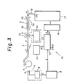
- Figure 3 is an explanatory view for the medical pump device in a preferred embodiment according to this invention
- Figure 4 is an explanatory view for a modified embodiment of the device in Figure 3
- Figure 5 is an explanatory view for another modified embodiment of the device in Figure 3
- Figure 6 is an explanatory view for a modified embodiment of a cam plate of the device in Figure 5
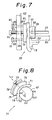
- Figure 7 is an explanatory view for a modified embodiment of a portion of the device in Figure 5
- Figure 8 is an explanatory view for a modified embodiment of a portion of the device in Figure 5
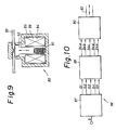
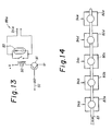
- Figures 9 through 14 are explanatory views for modified embodiments of the
- FIG 3 there are a heart 1, an artery 2 and a reconstructed artery 3.
- 4 is an electrocardiograph comprising a detector 5 and an amplifier 6, in which a waveform signal 7 including the R waves and corresponding to the heart beat is issued as shown in Figure 2(a).
- the duration TO between the two R waves is dependent on the kind of animal, metabolism (state of movement), etc.
- a phonocardiograph or the like may be used instead of the electrocardiograph 4.
- a blood flowmeter for detecting the change in the blood flow synchronized with the heart beat in the arterial portion upstream to the reconstructed artery 3 may be used instead of the electrocardiograph 4
- the form of the signal S to be outputted from the blood flowmeter 10 is So as shown in Figure 2(c) (similar to that in Figure l(a)).
- Such a normal blood flow waveform signal S 0 as shown in Figure 2(c) is stored in a memory 13.
- the shape of the blood flow waveform signal S outputted from the blood flowmeter 10 in the vicinity 3a of the reconstructed artery 3 is as shown by the reference S 1 in Figure 2(b) (typically, the same as the type II shown in Figure l(c) but, depending on the case, those similar to the type I or III shown in Figure 1(b) or (d), for which the judgement is difficult).
- the signal S 1 is substantially identical with the signal So for the rising point t l and the peak reaching point t 2 , but different from the normal blood flow waveform signal S 0 in that it has no backflowing region 14 between the time t 3 and the time t 5 and that the flow rate in the forward direction between the time t 1 and the time t 6 (substantially identical with time t 3 ) is smaller than that in the normal case.
- 16 is a pump driving circuit
- 17 is a pulsating pump having a single outlet/inlet 17a for the liquid
- 18 is a catheter for connecting the single outlet/inlet 17a of the pump 17 with the vicinity region 3a of the reconstructed artery 3, in which the pump driving circuit 16 drives the pump 17 based on the difference signal D so as to compensate the difference D, that is, reduce the difference D to add a pulsating movement to the vicinity region 3a of the reconstructed artery 3 by way of the catheter 18.
- Saline water incorporated with a blood coagulation inhibitor is filled inside of the catheter 18 and the pump 17.
- the pump 17 one having a high response speed, less leakage and less flow rate change is preferred.
- the treatment by the pump device 19 as has been described above is not necessarily applied permanently for a patient: it is usually sufficient to perform for about from two weeks to one month after the operation.
- the comparator 15 or the difference signal generator 15a may be a microprocessor or the like for the ease of computer-control. Further, the operation or manipulation parameters may be set manually while monitoring the blood flow waveform to thereby compensate the deviation from the normal one without using a comparator.
- the differential signal generator 15a various kinds of parameters as described later may be inputted by way of a key board, write pen or the like, the values for the operation parameters may be indicated on real time, or the flow rate pattern, that is, the blood flow waveform may be detected by means of a blood flowmeter 10 sometimes (for example, each time the pulse number changes) to automatically compensate the operation parameters.
- the driving circuit 16 may also be supplied with a signal K for performing discharge (suction) and suction (discharge) at a flow rate approximating to K 1 ⁇ D 1 during the period t 1 - t 2 (the period in which D 1 increases in the negative direction) or the period between the time t 6 (or t 3 ) - t 4 (the period in which D 1 increases in the positive direction), for example, as shown in Figure 2(e).
- the amount of discharging (sucking) and of sucking (discharging) through the catheter 18 may be different and, in the case of equalizing the amounts, the pattern may be different from D 1 or K 2 , K 3' for instance, by equally setting the volume V 1 , V 2 defined by K 2 , K 3 , or suction (discharge) may be performed by an amount corresponding to the volume V 1 between t 1 ⁇ t ⁇ t 3 and discharge (suction) may be performed by an amount corresponding to the volume V 1 within t 3 ⁇ t ⁇ t 5 or within the next heart beating time.
- These operation or manipulation parameters T 1 , T 3 , T 4 , T 5 , V 1 , V 2 may be determined in comparison with the normal blood flow waveform S 0 as a reference in the case of detecting the abnormal blood flow waveform S 1 upon observing the blood flow waveform after reconstructing operation, and may be set initially to the difference signal generator 15a.
- the adjusting range for the parameters T 1 , T 3 , T 4 , T 5 , V 1 , V 2 are, for example, as described below.
- T 1 t l - t 0 ⁇ 140 msec
- T 3 t 2 - t 1 ⁇ 50 msec
- T 4 t 3 - t 2 ⁇ 40 msec
- T 5 t 4 - t 3 ⁇ 60 msec.
- the delay time T 1 varies considerably depending on the rate of heart beat, but it is necessarily less than the period of the heart beat, it is only necessary to be variable about within a range from 0 to 1000 msec, assuming the number of heart beat of a living body as from 60 to 200 cycles/min.
- T 3 , T 4 , T 5 are attributable to the inherent movement of heart contraction and relaxation, it is generally set to be variable within a range from 0 to 500 msec even in the case where the device is made utilizable in a general purpose, irrespective of the kind of animals.
- variable adjusting range for the parameters T 1 , T 3 , T 4 , T 5' V 1 , V 2 may be broader than that as described above.
- 21 and 22 are delay circuits.
- the pulse signal generator 15a comprises the delay circuits 21, 22, the gates 23, 24 and the pulse signal generator 25.
- V l and V 2 can be adjusted by varying the frequency of the pulse from the pulse generator 25 or the diameter of the injection cylinder 34.
- FIG. 5 shows a medical pump device 40 as a further modified embodiment.
- the same elements as those in the pump device 19 or 20 in Figure 3 or 4 carry the common reference numerals.
- the control for the movement of the inner cylinder 35 in the direction D, E relative to the outer cylinder 32 is performed by urging a cam follower protrusion 47 of an end flange 45 of the outer cylinder 35 to the cam face 43 of a cam plate 42, connected to a power shaft 41 of the pulse motor 26, by means of a compression spring 46 between the flanges 44 and 45.
- a cam plate 48 as shown in Figure 6 having a constant diameter R l between the positions H 4 and H 1 , a constant diameter R 2 ( ⁇ R 1 ) between the positions H 2 and H 3 and a diameter monotonously changing between the positions H 1 and H 2 and positions H 3 and H 4 , respectively, may be used in place of the cam plate 42.
- 49 is a frequency setter for setting the generation frequency B f for the pulse B from the pulse generator 25 and 50 is a gate circuit for allowing the passage of the pulse signal B at the frequency B f for a predetermined time T a ((t 5 - t 0 ) ⁇ T a ⁇ TO) on every application of a trigger signal 9 from the trigger circuit 8.
- 51 is an initial position setter for setting the initial position G 0 for the cam plate 42 and it delivers an initial position signal G to the driving circuit 52 from the gate circuit 50 by the operation end signal F.
- the driving circuit 52 is a driving circuit for the step motor 26, and the driving circuit 52 sets the cam plate 42 to a position where the position G 0 defined by the setter 51 is abutted against the protrusion 47.
- the trigger circuit 8 is actuated and the pulse signal B at the frequency B f is applied to the driving circuit 52 passing through the gate circuit 50 for a period T a thereafter.
- the driving circuit 52 rotationally drives the cam 42 by way of the pulse motor 26 in the direction G at a speed defined with the frequency B f to control the movement of the inner cylinder 35 in the direction D, E and performs the discharge and sucking of the liquid to and from the vicinity 3a of the reconstructed artery by way of the catheter 18.
- the cam plate 42 is set again to the initial position GO under the control of the circuits 51, 52 after the period T a and before the delivery of the next signal 7.
- the difference signal generator 15a comprises the pulse generator 25, the gate circuit 50, the initial position setter 51, the driving circuit 52, the motor 26, the cam plate 42 and the cam follower protrusion 47.
- the time periods T 1 , T 3 , T 4 and T 5 are defined with angle G 0 LG 1 , angle G 1 LG 2 , angle G 2 LG 3 and angle G 3 LG 4 , while V 1 and V 2 are defined with the shape of the cam faces 43a and 43c from G 1 to G 2 and G 3 to G 4 , as well as the diameter for the injection cylinder-like pump 34.
- L represents a cam rotating center.
- a pump 55 as shown in Figure 7 may be used in place of the injection cylinder-like pump 34.
- the top end 56 of a connection rod 29 connected to a motor head is joined into the aperture 58 of a retainer member 57.
- the retainer member 57 is engaged at a recess 59 into a guide member 60 such that it is displaced in the direction D by the backward movement of the motor 26 and in the direction E by the forward movement of the motor 26.
- 61 is a support bed and its position in the direction D or E is adjusted by a stand position adjusting screw 64 screw-coupled to the threaded hole 63 in a frame 62.
- 65 and 66 are guide rods secured to the support bed 61 and the guide rods 65 and 66 penetrate guide holes 67 and 68, respectively, in the frame 62.
- 69 and 70 are compression springs.
- the displaced state as shown by the dotted chain (phantom line) at the portion 72 of a flexible tube 18 closed at one end 71 is changed, by which the inner volume of the tube 18 is changed to perform the discharge or sucking of the liquid.
- the flow rate V l , V 2 can be adjusted by varying the stroke in the direction D, E or the urging area.
- the tube 18 may be the catheter itself or a separate member in communication with the catheter 18, which can be made of a flexible baloon for instance.
- a solenoid pinch valve 80 has a structure as shown in Figure 9, in which a plunger 82 is urged upward by a spring 81 upon non-energized state and a tube 83 put therebetween is crushed (pinched).
- the solenoid 89 When the solenoid 89 is energized, the plunger 82 is attracted by the force of an electromagnet 84 to release the tube 83. Since the constant volume of the tube 83 varies depending on the pinching and releasing operation, the liquid in the tube 83 also moves left and rightward.
- a timing gate circuit 87 receives a synchronization input signal 9 from an electrocardiograph, etc and generates gate pulse signals with a time width nD l + D 2 + nD 3 (n is an integer) after a certain time delay D 0 + mD l (m is an integer).
- a relay switching circuit 88 receives the gate signals as described above to open and close a power relay. The relay circuit controls the electromagnetic opening and closure of the pinch valve 80 at the final stage.
- the timing gate circuit 87 has a constitution as shown in Figure 11. It comprises an input terminal 90 for a trigger signal 9; delay circuits D 0 , D 1 , D 2 and D 3' which generates timing trigger signals successively from the input time of the trigger signal 9 with appropriate time delays; and gate circuits G l - G 5 supplied with these timing trigger signals at inputs a, b as the gate ON or OFF signal to generate gate pulses G 1 - G 5 at a TTL level "1 (high)" only for the predetermined time width (from the ON trigger input time to the OFF trigger input time) from a predetermined time.
- delay times can variably be set by adjusters r 0 , r l - r 1 "', r 2 , r 3 - r 3 "'. r 1 - r 1 "' operate interlockingly and r 3 - r 3 "' also operate interlockingly.
- the relationship between the gate signals G l - G 5 finally outputted from the circuit 87 and the trigger input pulse is shown in Figure 12.
- G 1 "1" after the time D 0 from the trigger input signal rising time and, thereafter, G 2 - G 5 attain "1" with the time delay D 1 successively.
- These gate signals control a relay switching circuit 83 at the succeeding stage.
- the relay switching circuit 88 is arranged in five systems 88a, 88b, 88c, 88d, 88e (in parallel) corresponding to the signals G l - G 5 and an example of the circuit 88a is shown in Figure 13.
- a transistor 91 turns to ON or OFF state in accordanced with the TTL gate signals G 1 ---- G 5 to open or close a relay 92 connected therewith.
- a TTL-driven solid state relay (SSR), etc may be used.
- 93 is a surge absorber and 94a is an output from the relay switching circuit 88a.
- the five solenoid pinch valves 80a, ---- 80e are arranged as shown in Figure 14 and opened in the order of 80a - 80b - 80c - 80d - 80e, while closed in the order of 80e - 80d - 80c - 80b - 80a with the timing shown previously in accordance with the driving voltage ON-OFF 94a, ---- 94e from the relay circuits 88a ---- 88e, to suck or discharge the liquid in the tube 83 connected therewith successively.
- the gate signal connection is reversed (connecting the signal 94a to the valve 80e, ---- 94e to the valve 80a) and the gate output signal is reversed.
- a solenoid pinch valve which is opened a the deenergization state, while closed upon energization may be used.
- this device 86 is adapted as a serial liquid charge and discharge type, it may be operated while connecting the five tubes in parallel depending on the opening and closing times. Further, the variation for the moving volume can simply be attained by changing the tube diameter.
- smooth discharge can also be attained by one solenoid device 99 by selecting a device 100 as shown in Figure 15.
- a tube 102 to be urged is secured on a securing table 101 and a pinch arm 103 is secured at the left end thereof with a rotating fulcrum 104 while connected at the other end to the plunger 82a of a solenoid 99 at a position 105.
- the solenoid 99 actuates so as to attract downward the plunger 82a, the pinch arm 103 is pulled to successively urge the tube 102 from the left end and thereby discharge the liquid from the tube 102.
- the solenoid 99 performs the opening operation, the diameter of the tube 102 is restored by the opposite operation to suck the liquid.
- Devices 106 and 107 capable of variably adjusting the liquid charge and discharge amount continuously and finely, are shown in Figures 16 and 17, respectively.
- a pinch plate 110 secured with an acute angle to a solenoid plunger 108 by means of a moving screw 109 is used.
- the solenoid plunger 108 moves vertically (in the direction vertical to the sheet of Figure 16) and urges a tube 111 secured to a table (not shown) for a certain width W by the pinch plate 110.
- the pinch width W can be adjusted by moving the moving screw 109 thereby moving the pinch plate 110 in the direction X.
- the region 112 depicted by the hatched lines is a pinch region.
- the magnitude or the pinch area of a pinch region 116 is made variable thereby adjusting the charge and discharge amount by varying an angle Z of a securing table 115 for the tube 114 relative to a pinch plate 113 having a predetermined width Y.
- 117 is a fulcrum.
- a device 139 for a further modified embodiment is shown in Figure 18.
- Circular members 122, 123 made of an acrylic or "Teflon" resin, with recessed faces 120, 121, respectively, at the middle portion thereof are prepared.
- a flexible thin sheet 124 of silicon rubber or the like is put therebetween to constitute a diaphragm as shown in the drawing.
- a liquid charge or discharge tube 125 and a vent 127 with a valve 126 are attached to the upper vessel 123, while a tube 128 for diaphragm actuating fluid is attached to the lower vessel 122. Liquid to be delivered or sucked is filled on the upper side of the diaphragm sheet 124.
- the tube 128 coming out of the lower vessel 122 is divided into two systems and connected to delivering and sucking devices 130 and 131. They are respectively connected to a high pressure source 136 and a low pressure source 137 for hydraulic fluid by way of flow rate control valves 132 and 133 and operation controlling solenoid valves 134 and 135, opened or closed by electrical signals, respectively. While air, oil, etc are used as the hydraulic fluid, since air may cause a delay in response due to its compressible nature, oil pressure is desirable for the high speed operation.
- the relationship between the open and close signals G H and G L for the solenoid valves 134 and 135 together with the trigger input signal are shown in Figure 19(a), (b).
- a control signal as shown in Figure 19(a) may be used, assuming that there is no operation delay and the response is quick as in the oil pressure system.
- Delay times d l and d 2 are disposed as shown in Figure 19(b), where there is a response delay as in the pneumatic pressure system.
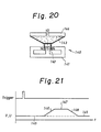
- FIGS 20 and 21 shown a still further modified embodiment.
- This device 140 of a coreless or cored dynamoelectric driven electromagnet type like a loud speaker, utilizes the phenomenon that the moding electromagnet 142 moves by supplying an electrical current into the electromagnet 142 placed in the magnetic field of a permanent magnet 141.
- the upper end of the moving electromagnet 142 is secured to the center of a diaphragm 143 made of a flexible membrane such as silicon rubber.
- the diaphragm 143 is moved along with the displacement of the moving electromagnet 142, by which the liquid between the diaphragm 143 and the flange 144 moves.
- the operation for sucking, stopping and delivery can be performed by controlling the electrical current U flowing through the moving electromagnet 142 as shown in Figure 21.
- 145 corresponds to the initial displacement (position), 146 to the sucking (or delivering) operation, 147 to the final displacement (position) and 148 to the delivering (or sucking) operation.
Landscapes
- Health & Medical Sciences (AREA)
- Engineering & Computer Science (AREA)
- Heart & Thoracic Surgery (AREA)
- Cardiology (AREA)
- Veterinary Medicine (AREA)
- Public Health (AREA)
- Biomedical Technology (AREA)
- Hematology (AREA)
- Life Sciences & Earth Sciences (AREA)
- Animal Behavior & Ethology (AREA)
- General Health & Medical Sciences (AREA)
- Anesthesiology (AREA)
- Mechanical Engineering (AREA)
- Vascular Medicine (AREA)
- Medical Informatics (AREA)
- Human Computer Interaction (AREA)
- External Artificial Organs (AREA)
- Measuring Pulse, Heart Rate, Blood Pressure Or Blood Flow (AREA)
Abstract
Applications Claiming Priority (2)
| Application Number | Priority Date | Filing Date | Title |
|---|---|---|---|
| JP60071997A JPS61232859A (ja) | 1985-04-05 | 1985-04-05 | 医用ポンプ装置 |
| JP71997/85 | 1985-04-05 |
Publications (2)
| Publication Number | Publication Date |
|---|---|
| EP0217964A1 true EP0217964A1 (fr) | 1987-04-15 |
| EP0217964A4 EP0217964A4 (fr) | 1987-07-30 |
Family
ID=13476623
Family Applications (1)
| Application Number | Title | Priority Date | Filing Date |
|---|---|---|---|
| EP19860902475 Withdrawn EP0217964A4 (fr) | 1985-04-05 | 1986-04-04 | Appareil medical a pompe. |
Country Status (5)
| Country | Link |
|---|---|
| US (1) | US5006111A (fr) |
| EP (1) | EP0217964A4 (fr) |
| JP (1) | JPS61232859A (fr) |
| AU (1) | AU573438B2 (fr) |
| WO (1) | WO1986005697A1 (fr) |
Cited By (5)
| Publication number | Priority date | Publication date | Assignee | Title |
|---|---|---|---|---|
| WO1990015630A1 (fr) * | 1989-06-20 | 1990-12-27 | Sphinx Medical Limited | Ameliorations du flux sanguin |
| US8571658B2 (en) | 2003-10-31 | 2013-10-29 | Sunshine Heart Company Pty Ltd | Synchronization control system |
| US8702583B2 (en) | 2003-11-11 | 2014-04-22 | Sunshine Heart Company Pty, Ltd. | Actuator for a heart assist device |
| US8777833B2 (en) | 2002-11-15 | 2014-07-15 | Sunshine Heart Company Pty. Ltd. | Heart assist device utilising aortic deformation |
| US9042979B2 (en) | 2010-04-02 | 2015-05-26 | Sunshine Heart Company Pty Limited | Combination heart assist systems, methods, and devices |
Families Citing this family (48)
| Publication number | Priority date | Publication date | Assignee | Title |
|---|---|---|---|---|
| US5639373A (en) | 1995-08-11 | 1997-06-17 | Zenon Environmental Inc. | Vertical skein of hollow fiber membranes and method of maintaining clean fiber surfaces while filtering a substrate to withdraw a permeate |
| DE69230766T2 (de) * | 1991-08-07 | 2000-08-31 | Usf Filtration Ltd., South Windsor | Konzentration von feststoffen in einer aufschlammung unter anwendung von kohlfasermembranen |
| US8852438B2 (en) | 1995-08-11 | 2014-10-07 | Zenon Technology Partnership | Membrane filtration module with adjustable header spacing |
| US20040238432A1 (en) | 1995-08-11 | 2004-12-02 | Mailvaganam Mahendran | Membrane filtration module with adjustable header spacing |
| US6422990B1 (en) * | 1997-11-26 | 2002-07-23 | Vascor, Inc. | Blood pump flow rate control method and apparatus utilizing multiple sensors |
| US5928131A (en) * | 1997-11-26 | 1999-07-27 | Vascor, Inc. | Magnetically suspended fluid pump and control system |
| US8364229B2 (en) | 2003-07-25 | 2013-01-29 | Dexcom, Inc. | Analyte sensors having a signal-to-noise ratio substantially unaffected by non-constant noise |
| US7613491B2 (en) | 2002-05-22 | 2009-11-03 | Dexcom, Inc. | Silicone based membranes for use in implantable glucose sensors |
| US7494459B2 (en) * | 2003-06-26 | 2009-02-24 | Biophan Technologies, Inc. | Sensor-equipped and algorithm-controlled direct mechanical ventricular assist device |
| US20060167334A1 (en) * | 2003-06-26 | 2006-07-27 | Anstadt Mark P | Method and apparatus for direct mechanical ventricular actuation with favorable conditioning and minimal heart stress |
| US9763609B2 (en) | 2003-07-25 | 2017-09-19 | Dexcom, Inc. | Analyte sensors having a signal-to-noise ratio substantially unaffected by non-constant noise |
| US20190357827A1 (en) | 2003-08-01 | 2019-11-28 | Dexcom, Inc. | Analyte sensor |
| US8886273B2 (en) | 2003-08-01 | 2014-11-11 | Dexcom, Inc. | Analyte sensor |
| US8626257B2 (en) | 2003-08-01 | 2014-01-07 | Dexcom, Inc. | Analyte sensor |
| US7591801B2 (en) | 2004-02-26 | 2009-09-22 | Dexcom, Inc. | Integrated delivery device for continuous glucose sensor |
| US7920906B2 (en) | 2005-03-10 | 2011-04-05 | Dexcom, Inc. | System and methods for processing analyte sensor data for sensor calibration |
| US7494477B2 (en) * | 2003-09-02 | 2009-02-24 | Pulsecath B.V. | Catheter pump, catheter and fittings therefore and methods of using a catheter pump |
| US9247900B2 (en) | 2004-07-13 | 2016-02-02 | Dexcom, Inc. | Analyte sensor |
| US8287453B2 (en) | 2003-12-05 | 2012-10-16 | Dexcom, Inc. | Analyte sensor |
| US8425416B2 (en) | 2006-10-04 | 2013-04-23 | Dexcom, Inc. | Analyte sensor |
| US8364231B2 (en) | 2006-10-04 | 2013-01-29 | Dexcom, Inc. | Analyte sensor |
| US8423114B2 (en) | 2006-10-04 | 2013-04-16 | Dexcom, Inc. | Dual electrode system for a continuous analyte sensor |
| US8364230B2 (en) | 2006-10-04 | 2013-01-29 | Dexcom, Inc. | Analyte sensor |
| US8425417B2 (en) | 2003-12-05 | 2013-04-23 | Dexcom, Inc. | Integrated device for continuous in vivo analyte detection and simultaneous control of an infusion device |
| US11633133B2 (en) | 2003-12-05 | 2023-04-25 | Dexcom, Inc. | Dual electrode system for a continuous analyte sensor |
| US8532730B2 (en) | 2006-10-04 | 2013-09-10 | Dexcom, Inc. | Analyte sensor |
| WO2009048462A1 (fr) | 2007-10-09 | 2009-04-16 | Dexcom, Inc. | Système d'administration d'insuline intégré avec un capteur de glucose en continu |
| US8808228B2 (en) | 2004-02-26 | 2014-08-19 | Dexcom, Inc. | Integrated medicament delivery device for use with continuous analyte sensor |
| US8886272B2 (en) | 2004-07-13 | 2014-11-11 | Dexcom, Inc. | Analyte sensor |
| US7783333B2 (en) | 2004-07-13 | 2010-08-24 | Dexcom, Inc. | Transcutaneous medical device with variable stiffness |
| US8989833B2 (en) | 2004-07-13 | 2015-03-24 | Dexcom, Inc. | Transcutaneous analyte sensor |
| EP1674119A1 (fr) * | 2004-12-22 | 2006-06-28 | Tecnobiomedica S.p.A. | Un dispositif pulsatoire, méthode d'actionnement dudit dispositif, système correspondant et programme informatique |
| US20100152523A1 (en) * | 2005-11-28 | 2010-06-17 | Myocardiocare, Inc. | Method and Apparatus for Minimally Invasive Direct Mechanical Ventricular Actuation |
| US8298142B2 (en) | 2006-10-04 | 2012-10-30 | Dexcom, Inc. | Analyte sensor |
| US8449464B2 (en) | 2006-10-04 | 2013-05-28 | Dexcom, Inc. | Analyte sensor |
| US8478377B2 (en) | 2006-10-04 | 2013-07-02 | Dexcom, Inc. | Analyte sensor |
| US8447376B2 (en) | 2006-10-04 | 2013-05-21 | Dexcom, Inc. | Analyte sensor |
| US8562528B2 (en) | 2006-10-04 | 2013-10-22 | Dexcom, Inc. | Analyte sensor |
| US8275438B2 (en) | 2006-10-04 | 2012-09-25 | Dexcom, Inc. | Analyte sensor |
| US20200037875A1 (en) | 2007-05-18 | 2020-02-06 | Dexcom, Inc. | Analyte sensors having a signal-to-noise ratio substantially unaffected by non-constant noise |
| US20080306444A1 (en) | 2007-06-08 | 2008-12-11 | Dexcom, Inc. | Integrated medicament delivery device for use with continuous analyte sensor |
| US8396528B2 (en) | 2008-03-25 | 2013-03-12 | Dexcom, Inc. | Analyte sensor |
| CN100594950C (zh) * | 2008-05-15 | 2010-03-24 | 上海交通大学 | 气动直接心室辅助装置 |
| US20110196189A1 (en) * | 2010-02-09 | 2011-08-11 | Myocardiocare, Inc. | Extra-cardiac differential ventricular actuation by inertial and baric partitioning |
| EP3575796B1 (fr) | 2011-04-15 | 2020-11-11 | DexCom, Inc. | Étalonnage avancé de capteur d'échantillon à analyser et détection d'erreur avancée |
| US11382540B2 (en) | 2017-10-24 | 2022-07-12 | Dexcom, Inc. | Pre-connected analyte sensors |
| US11331022B2 (en) | 2017-10-24 | 2022-05-17 | Dexcom, Inc. | Pre-connected analyte sensors |
| US11383076B2 (en) | 2020-10-01 | 2022-07-12 | Lifebridge Technologies, Llc | Pump regulation based on heart size and function |
Family Cites Families (18)
| Publication number | Priority date | Publication date | Assignee | Title |
|---|---|---|---|---|
| US3592183A (en) * | 1969-05-27 | 1971-07-13 | David H Watkins | Heart assist method and apparatus |
| US3885251A (en) * | 1973-03-05 | 1975-05-27 | Philips Corp | Artificial heart pump or assist |
| US3911897A (en) * | 1974-04-05 | 1975-10-14 | Jr Frank A Leachman | Heart assist device |
| US4080958A (en) * | 1976-02-27 | 1978-03-28 | Datascope Corporation | Apparatus for aiding and improving the blood flow in patients |
| US4135253A (en) * | 1976-11-30 | 1979-01-23 | Medtronic, Inc. | Centrifugal blood pump for cardiac assist |
| US4154227A (en) * | 1977-10-11 | 1979-05-15 | Krause Horst E | Method and apparatus for pumping blood within a vessel |
| US4250872A (en) * | 1978-05-25 | 1981-02-17 | Yehuda Tamari | Blood pulsating and/or pumping device |
| US4231354A (en) * | 1978-07-14 | 1980-11-04 | Howmedica, Incorporated | Pulsatile blood pumping apparatus and method |
| FR2470593A2 (fr) * | 1979-01-22 | 1981-06-12 | Lapeyre Didier | Nouvelle prothese cardiaque totale |
| FR2458288A1 (fr) * | 1979-06-11 | 1981-01-02 | Belenger Jacques | Pompe medicale destinee a l'assistance cardiaque pulsative |
| US4432468A (en) * | 1981-02-06 | 1984-02-21 | Siff Elliott J | Intravenous delivery system |
| US4466804A (en) * | 1981-09-25 | 1984-08-21 | Tsunekazu Hino | Extracorporeal circulation of blood |
| JPS58143763A (ja) * | 1982-02-19 | 1983-08-26 | 日野 恒和 | 血液の体外循環装置 |
| US4546759A (en) * | 1983-07-29 | 1985-10-15 | Mladen Solar | Method and apparatus for assisting human heart function |
| FR2550583B1 (fr) * | 1983-08-08 | 1986-03-28 | Delecroix Michel | Dispositif de regulation d'une pompe |
| JPS60142859A (ja) * | 1983-12-29 | 1985-07-29 | 泉工医科工業株式会社 | 拍動血流量自動設定機構付ロ−ラポンプ |
| FR2577424B1 (fr) * | 1985-02-20 | 1989-04-28 | Gilles Karcher | Pompe de perfusion coronaire |
| US4782817A (en) * | 1987-05-29 | 1988-11-08 | Abiomed Cardiovascular, Inc. | Ventricular support system |
-
1985
- 1985-04-05 JP JP60071997A patent/JPS61232859A/ja active Pending
-
1986
- 1986-04-04 AU AU56642/86A patent/AU573438B2/en not_active Ceased
- 1986-04-04 WO PCT/JP1986/000163 patent/WO1986005697A1/fr not_active Ceased
- 1986-04-04 EP EP19860902475 patent/EP0217964A4/fr not_active Withdrawn
-
1988
- 1988-07-18 US US07/220,990 patent/US5006111A/en not_active Expired - Fee Related
Cited By (10)
| Publication number | Priority date | Publication date | Assignee | Title |
|---|---|---|---|---|
| WO1990015630A1 (fr) * | 1989-06-20 | 1990-12-27 | Sphinx Medical Limited | Ameliorations du flux sanguin |
| US5372573A (en) * | 1989-06-20 | 1994-12-13 | British Technology Group Limited | Blood flow |
| EP0923954A3 (fr) * | 1989-06-20 | 1999-08-11 | Btg International Limited | Améliorations du flux sanguin |
| US8777833B2 (en) | 2002-11-15 | 2014-07-15 | Sunshine Heart Company Pty. Ltd. | Heart assist device utilising aortic deformation |
| US9555176B2 (en) | 2002-11-15 | 2017-01-31 | Sunshine Heart Company Pty, Ltd. | Implantable device utilizing arterial deformation |
| US8571658B2 (en) | 2003-10-31 | 2013-10-29 | Sunshine Heart Company Pty Ltd | Synchronization control system |
| US9119908B2 (en) | 2003-10-31 | 2015-09-01 | Sunshine Heart Company Pty. Ltd. | Synchronization control system |
| US9561375B2 (en) | 2003-10-31 | 2017-02-07 | Sunshine Heart Company Pty, Ltd. | Synchronization control system |
| US8702583B2 (en) | 2003-11-11 | 2014-04-22 | Sunshine Heart Company Pty, Ltd. | Actuator for a heart assist device |
| US9042979B2 (en) | 2010-04-02 | 2015-05-26 | Sunshine Heart Company Pty Limited | Combination heart assist systems, methods, and devices |
Also Published As
| Publication number | Publication date |
|---|---|
| WO1986005697A1 (fr) | 1986-10-09 |
| EP0217964A4 (fr) | 1987-07-30 |
| AU5664286A (en) | 1986-10-23 |
| AU573438B2 (en) | 1988-06-09 |
| JPS61232859A (ja) | 1986-10-17 |
| US5006111A (en) | 1991-04-09 |
Similar Documents
| Publication | Publication Date | Title |
|---|---|---|
| US5006111A (en) | Medical pump device and a method for compensating a deviation of a measured blood flow rate | |
| JP3420588B2 (ja) | 人工心肺装置における脈動流発生 | |
| JP2532637B2 (ja) | 血液ポンプ装置と方法 | |
| US4610658A (en) | Automated peritoneovenous shunt | |
| US3505987A (en) | Intra-aortic heart pump | |
| US4046137A (en) | Solenoid operated blood pump drive system | |
| US3842440A (en) | Implantable linear motor prosthetic heart and control system therefor | |
| EP0329765B1 (fr) | Dispositifs prothetiques servant a retablir l'elasticite arterielle | |
| US3911898A (en) | Heart assist method and device | |
| EP0454353A1 (fr) | Dispositif et méthode pour pomper des liquides surtout des liquides biologiques | |
| JPH0653160B2 (ja) | 拍動発生方法及び装置 | |
| JPH11509457A (ja) | 移植可能なポンプおよび補綴具 | |
| IL311989B1 (en) | Systems and methods for ex-vivo organ care | |
| Reul et al. | In vitro comparison of bileaflet aortic heart valve prostheses: St. Jude Medical, CarboMedics, modified Edwards-Duromedics, and Sorin-Bicarbon valves | |
| US3791767A (en) | Dialysis pumping system | |
| KR101871030B1 (ko) | 초정밀 맥동유동 발생장치, 그 맥동유동 발생장치를 갖는 인공 맥상파 재현 시스템 및 재현방법 | |
| Pech et al. | Peristaltic pump with continuous flow and programmable flow pulsation | |
| JPH09502377A (ja) | 筋肉エネルギー変換器 | |
| US20060236756A1 (en) | Pulsator device, method of operating same, corresponding system and computer program product | |
| CN120251487A (zh) | 一种脉动泵系统、医疗器械植介入模拟系统及控制方法 | |
| Björk et al. | A mechanical pulse duplicator for testing prosthetic mitral and aortic valves | |
| Schichl et al. | A computer controlled versatile pulse duplicator for precision testing of artificial heart valves | |
| CN113367669B (zh) | 一种脉搏复现系统及其控制方法、复现方法 | |
| JPS5869577A (ja) | 血管拡張用装置 | |
| EP0028218A4 (fr) | Methode et appareil de pompage de sang dans un recipient. |
Legal Events
| Date | Code | Title | Description |
|---|---|---|---|
| PUAI | Public reference made under article 153(3) epc to a published international application that has entered the european phase |
Free format text: ORIGINAL CODE: 0009012 |
|
| 17P | Request for examination filed |
Effective date: 19861127 |
|
| AK | Designated contracting states |
Kind code of ref document: A1 Designated state(s): DE FR GB IT |
|
| A4 | Supplementary search report drawn up and despatched |
Effective date: 19870730 |
|
| 17Q | First examination report despatched |
Effective date: 19890523 |
|
| STAA | Information on the status of an ep patent application or granted ep patent |
Free format text: STATUS: THE APPLICATION IS DEEMED TO BE WITHDRAWN |
|
| 18D | Application deemed to be withdrawn |
Effective date: 19910309 |
|
| RIN1 | Information on inventor provided before grant (corrected) |
Inventor name: MUTO, YOICHI5-4-11-203, HAKOZAKI Inventor name: SHIRAKAMI, TOSHIHARU Inventor name: KAWAI, YOSHIO Inventor name: INOKUCHI, KIYOSHI1-3-47, TERAZUKA Inventor name: OKADOME, KENICHIRO2-11-28-501, YAKUIN Inventor name: ONUMA, TADASHI |