EP0218018A1 - Appareil d'entraînement - Google Patents
Appareil d'entraînement Download PDFInfo
- Publication number
- EP0218018A1 EP0218018A1 EP86109703A EP86109703A EP0218018A1 EP 0218018 A1 EP0218018 A1 EP 0218018A1 EP 86109703 A EP86109703 A EP 86109703A EP 86109703 A EP86109703 A EP 86109703A EP 0218018 A1 EP0218018 A1 EP 0218018A1
- Authority
- EP
- European Patent Office
- Prior art keywords
- cylinder
- piston
- training device
- lever
- pivot shaft
- Prior art date
- Legal status (The legal status is an assumption and is not a legal conclusion. Google has not performed a legal analysis and makes no representation as to the accuracy of the status listed.)
- Granted
Links
- 230000033001 locomotion Effects 0.000 claims abstract description 22
- 239000012530 fluid Substances 0.000 claims abstract description 6
- 210000003205 muscle Anatomy 0.000 description 7
- 210000003414 extremity Anatomy 0.000 description 3
- 210000002414 leg Anatomy 0.000 description 3
- 229910000831 Steel Inorganic materials 0.000 description 2
- 230000005540 biological transmission Effects 0.000 description 2
- 238000010276 construction Methods 0.000 description 2
- 210000001624 hip Anatomy 0.000 description 2
- 210000000629 knee joint Anatomy 0.000 description 2
- 210000000323 shoulder joint Anatomy 0.000 description 2
- 239000010959 steel Substances 0.000 description 2
- 238000005728 strengthening Methods 0.000 description 2
- 208000016593 Knee injury Diseases 0.000 description 1
- 208000029549 Muscle injury Diseases 0.000 description 1
- 230000006978 adaptation Effects 0.000 description 1
- 230000001270 agonistic effect Effects 0.000 description 1
- 210000003423 ankle Anatomy 0.000 description 1
- 230000003042 antagnostic effect Effects 0.000 description 1
- 238000005452 bending Methods 0.000 description 1
- 210000001520 comb Anatomy 0.000 description 1
- 238000013500 data storage Methods 0.000 description 1
- 230000000694 effects Effects 0.000 description 1
- 210000000245 forearm Anatomy 0.000 description 1
- 210000004394 hip joint Anatomy 0.000 description 1
- 210000003127 knee Anatomy 0.000 description 1
- 210000003041 ligament Anatomy 0.000 description 1
- 239000007788 liquid Substances 0.000 description 1
- 230000002980 postoperative effect Effects 0.000 description 1
- 230000006641 stabilisation Effects 0.000 description 1
- 238000011105 stabilization Methods 0.000 description 1
- 230000003068 static effect Effects 0.000 description 1
- 210000000689 upper leg Anatomy 0.000 description 1
- 210000000707 wrist Anatomy 0.000 description 1
Images


Classifications
-
- A—HUMAN NECESSITIES
- A63—SPORTS; GAMES; AMUSEMENTS
- A63B—APPARATUS FOR PHYSICAL TRAINING, GYMNASTICS, SWIMMING, CLIMBING, OR FENCING; BALL GAMES; TRAINING EQUIPMENT
- A63B21/00—Exercising apparatus for developing or strengthening the muscles or joints of the body by working against a counterforce, with or without measuring devices
- A63B21/008—Exercising apparatus for developing or strengthening the muscles or joints of the body by working against a counterforce, with or without measuring devices using hydraulic or pneumatic force-resisters
- A63B21/0083—Exercising apparatus for developing or strengthening the muscles or joints of the body by working against a counterforce, with or without measuring devices using hydraulic or pneumatic force-resisters of the piston-cylinder type
-
- A—HUMAN NECESSITIES
- A63—SPORTS; GAMES; AMUSEMENTS
- A63B—APPARATUS FOR PHYSICAL TRAINING, GYMNASTICS, SWIMMING, CLIMBING, OR FENCING; BALL GAMES; TRAINING EQUIPMENT
- A63B21/00—Exercising apparatus for developing or strengthening the muscles or joints of the body by working against a counterforce, with or without measuring devices
- A63B21/00058—Mechanical means for varying the resistance
- A63B21/00076—Mechanical means for varying the resistance on the fly, i.e. varying the resistance during exercise
-
- A—HUMAN NECESSITIES
- A63—SPORTS; GAMES; AMUSEMENTS
- A63B—APPARATUS FOR PHYSICAL TRAINING, GYMNASTICS, SWIMMING, CLIMBING, OR FENCING; BALL GAMES; TRAINING EQUIPMENT
- A63B21/00—Exercising apparatus for developing or strengthening the muscles or joints of the body by working against a counterforce, with or without measuring devices
- A63B21/40—Interfaces with the user related to strength training; Details thereof
- A63B21/4041—Interfaces with the user related to strength training; Details thereof characterised by the movements of the interface
- A63B21/4047—Pivoting movement
Definitions
- the invention relates to a training device according to the preamble of patent claim 1.
- a lever provided with two handles is pivotably mounted on a vertical support about a horizontal axis.
- the piston rod of the hydraulic cylinder-cylinder unit is articulated to the lever between the handles and the articulation point on the support, the cylinder of which is articulated below the articulated connection of the lever to the support.
- the lever provided with handles can only be pressed down or raised for exercise purposes, so that this has only a limited area of application having.
- the possible uses of the known training device can not be expanded easily because the lever with the hydraulic cylinder and the support is a space-consuming construction that can be difficult to adapt to other movements to achieve other training effects.
- the object of the invention is therefore to provide a training device of the type mentioned, the unit generating the reaction moment and consisting of the lever and the hydraulic cylinder has a stable space-saving construction, so that it can be easily adapted to different exercises.
- the reaction torque is generated in a manner known per se when the lever is pivoted in that the hydraulic fluid is displaced by the piston depending on its direction of movement from one cylinder chamber to the other, the magnitude of the reaction torque depending on the throttling of the hydraulic Liquid in the channel and the throttle device depends. Since the reaction torque increases approximately with the square of the angular speed of the pivoting movement of the lever, the patient or the practitioner can choose the desired resistance through the speed of the movement carried out. If the reaction moment becomes too large, the practicing person can interrupt the movement at any time, which also means that the reaction moment becomes zero. In the event of an interruption, there are no forces on the limbs or body parts to be trained more one. If the practicing person resumes the movement, he can practically increase the reaction moment starting from zero, since almost no resistance to static friction can be overcome.
- the training device according to the invention can thus be used in an ideal manner with gentle treatment, and high stress levels are also possible.
- the unit generating the reaction moment for the exercising person consists of the lever articulated directly from the hydraulic cylinder, it can be arranged in a space-saving manner in such a way that a large number of different exercises can be carried out.
- a training device in which a lever is connected to a pivot shaft, the rotational movement of which is transmitted by a chain drive to a second pivot shaft, to which a lever is connected, to which one end of a gas spring is articulated , whose other end is pivotally mounted in the frame.
- This known training device is provided with a very complex and space-consuming gear for converting a rotary movement into a translatory movement, so that the adaptation of this device to different exercises requires an additional considerable design effort.
- the throttle device expediently consists of an adjustable throttle valve. By setting the throttle cross-section, the achievable resistance or the desired reaction torque can be adapted to the respective training conditions.
- an adjustable throttle valve is arranged in the end regions of the channel arranged in the cylinder wall or through it, that the piston consists of two rigidly connected piston disks which delimit a piston chamber between them, that in each piston disk a check valve permitting a flow into the adjacent cylinder chamber is arranged and that the channel between the throttle valves is provided with a line opening through the cylinder wall into the piston chamber.
- This configuration allows the throttle valves to be set to different cross sections, so that the forward movement takes place at the same speed with a different reaction torque than the return movement. This can be appropriate according to the limbs or body parts to be trained and moved and according to the selected training program.
- the hydraulic fluid displaced from a cylinder chamber is essentially throttled only by the adjacent throttle valve and can then through the piston chamber and the opposite Flow the non-return valve into the other cylinder chamber bypassing the other throttle valve.
- the transmission can be formed in an advantageous and simple manner in that the pivot shaft extends through the cylinder between the piston disks and is mounted in opposite areas of the cylinder wall and in that the piston between the piston disks is provided with an axially parallel rack, with which one with the pivot shaft fixed pinion combs.
- the transmission can also be formed by a crank and a connecting rod or eccentric.
- the cylinder is expediently connected to the training device consisting of a chair, a couch or the like in such a way that the pivot shaft is essentially aligned with the axis of the joint or diffraction center of the limb or body part to be trained.
- the cylinder is connected to the pivot shaft of a second cylinder of the same type attached to the training device in such a way that it is aligned with the longitudinal axis of the first cylinder.
- This configuration enables, as it were, cardanic spatial movements, such as are useful for training hip or shoulder joints, for example.
- the cylinder can be provided with at least one device that measures the pressure of the hydraulic fluid in a cylinder chamber.
- This device can display the respective reaction moment to the patient or the doctor.
- a device can be provided which displays the measured pressure and / or determines the work and / or the power from this and displays and / or registers this.
- the work done by the patient can be calculated from the respective resistance and the swivel angles, the angular velocity still having to be measured to determine the power.
- the swivel angle of the lever can be adjusted by stops. Furthermore, the length of the lever arm of the lever is expediently adjustable.
- the gymnastic device according to the invention consists, for example, of a training chair
- the lower leg of the patient can be attached to the lever by means of padded pressure plates and fixing straps.
- the thigh lies firmly on the seat of the chair and is also fixed by means of straps.
- a lap belt can be provided to stabilize the hips and torso.
- the pressure shell is expediently rotatably mounted in its starting point on the length-adjustable lever arm and can also be adjusted to the required length of the patient's spine, so that the drawer load on the knee joint ligaments is kept as low as possible.
- the training device makes it possible to keep the risk of stress on the patient's joint apparatus as low as possible. Therefore, adjustment, support and stabilization devices should be provided at the required points.
- the muscles to be trained can be moved as much as possible by the patient in order to achieve the greatest possible training success in the shortest possible time.
- Controlling measuring devices can give the patient or exerciser and also the therapist a constant overview of the load and the success of the exercise programs. Data storage for statistics and program design is also possible.
- a pivot point can be determined which corresponds to the imaginary center of the joint.
- a hinge joint there is a turning line. It is the imaginary plumb line through all the planes lying in the longitudinal direction of the two legs. Two planes perpendicular to each other intersect at the pivot point.
- the axis of rotation or the fulcrum of the lever should be able to track and fix spatially the imaginary center of the joint.
- the circular movement of the two legs can be converted into a rectified forward and backward thrust of the hydraulic hydraulic piston.
- the throttle device can consist of a work compensation duct, the overflow bores of which are arranged so that it can be used for the directions of movement, by means of two throttle screws.
- a multi-channel system with several throttle screws can also be used.
- the rotary movement can be registered using a rotary encoder and visualized on a digital or analog display, which can be set to the starting or end position from any position.
- the oil pressure can be detected by pressure sensors and made visible either digitally or in an analog way.
- the measured values recorded can be fed directly to a data processing system, stored, evaluated and printed out.
- the range of motion of the joint to be trained can be limited by lockable stops.
- the patient's medical data can be entered, for example the weight of the lower leg, which falls back completely relaxed from stretching.
- both the agonistic and the antagonistic side can be trained.
- the device according to the invention can be used in the form of a training chair, for example, for strengthening and general aftercare of postoperative knee and muscle injuries. Furthermore, the training device according to the invention can be used to strengthen the entire ankle muscles in the pronation-supination and dorsal-plantar flexion range.
- the training device according to the invention can also be used with particular advantage for general and special strengthening of the trunk muscles while keeping the spinal area in good condition.
- the entire hip area, including the gruteal muscles, can be trained with the device. It can also be used, for example, to move the muscle parts of the shoulder joint to strengthen the various areas of movement. It can also be used to strengthen the forearm and wrist muscles.
- the training device consists of a chair 1, which is only indicated by the seat, backrest and legs.
- the hydraulic cylinder 2 is fastened to the seat surface with the pivot lever 3 in such a way that the pivot axis is approximately aligned with the line drawn through the patient's two knee joints.
- a cross piece 4 is attached at the end, which carries bandages for attachment to the lower leg of the patient.
- the chair 1 is also provided with fastening straps (not shown) for the patient who is only shown by lines.
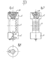
- the hydraulic cylinder is shown schematically in FIG. 2.
- a piston acting on both sides which consists of the two piston disks 5, 6, which are rigidly connected to one another by the toothed rack 7.
- a pivot shaft, on which the pinion 8 is wedged, is mounted in opposite areas of the cylinder wall.
- the pinion 8 meshes with the rack 7.
- the pivot lever 3 is wedged onto the pivot shaft.
- the cylinder chambers 9, 10, which are divided by the piston disks 5, 6, are connected to one another by a channel 11 in which a throttle valve 12 is arranged.
- the throttle duct 11 is arranged in the cylinder wall.
- the end regions of the channel are provided with bores 12, 13 which open into the cylinder chambers 9, 10.
- the cylinder In its central region, the cylinder has a transverse bore 14 in which the pivot shaft is mounted with the pinion which meshes with the rack.
- the channel 11 has in its central region next to the transverse bore 14 a transverse bore 15 which opens into the piston chamber between the piston discs 5, 6.
- the channel is penetrated by threaded bores 16, 17 into which throttle screws can be screwed, through which the respective throttle cross section can be adjusted.
- the design of the piston can be seen in more detail in FIGS. 6 to 8.
- the piston consists of the end-side piston disks 5, 6, which are connected to one another by the toothed rack 7.
- the piston disks 5, 6 are provided with stepped axial bores 19, 20, into which steel balls 21, 22 forming check valves are inserted. These steel balls are secured against falling out by screwed-on locking plates in the manner shown.
Landscapes
- Health & Medical Sciences (AREA)
- Life Sciences & Earth Sciences (AREA)
- Biophysics (AREA)
- Orthopedic Medicine & Surgery (AREA)
- General Health & Medical Sciences (AREA)
- Physical Education & Sports Medicine (AREA)
- Rehabilitation Tools (AREA)
Priority Applications (1)
| Application Number | Priority Date | Filing Date | Title |
|---|---|---|---|
| AT86109703T ATE56887T1 (de) | 1985-07-22 | 1986-07-15 | Trainingsgeraet. |
Applications Claiming Priority (2)
| Application Number | Priority Date | Filing Date | Title |
|---|---|---|---|
| DE3526144 | 1985-07-22 | ||
| DE19853526144 DE3526144A1 (de) | 1985-07-22 | 1985-07-22 | Trainingsgeraet |
Publications (2)
| Publication Number | Publication Date |
|---|---|
| EP0218018A1 true EP0218018A1 (fr) | 1987-04-15 |
| EP0218018B1 EP0218018B1 (fr) | 1990-09-26 |
Family
ID=6276407
Family Applications (1)
| Application Number | Title | Priority Date | Filing Date |
|---|---|---|---|
| EP86109703A Expired - Lifetime EP0218018B1 (fr) | 1985-07-22 | 1986-07-15 | Appareil d'entraînement |
Country Status (3)
| Country | Link |
|---|---|
| EP (1) | EP0218018B1 (fr) |
| AT (1) | ATE56887T1 (fr) |
| DE (1) | DE3526144A1 (fr) |
Cited By (3)
| Publication number | Priority date | Publication date | Assignee | Title |
|---|---|---|---|---|
| EP0275956A3 (fr) * | 1987-01-22 | 1989-01-04 | Günter Kern | Appareil de diagnostic médical |
| WO2003080189A1 (fr) * | 2002-03-25 | 2003-10-02 | Bon-Su Ku | Systeme hydraulique d'organisation de mouvement polyvalent |
| EP1588742A1 (fr) * | 2004-04-21 | 2005-10-26 | Josef Mittermaier | Appareil d'entraínement |
Families Citing this family (11)
| Publication number | Priority date | Publication date | Assignee | Title |
|---|---|---|---|---|
| DE3701821A1 (de) * | 1986-12-05 | 1988-06-16 | Kern Guenter | Trainingsgeraet |
| DE3704841C2 (de) * | 1987-02-16 | 1996-06-13 | Kern Guenter | Trainingsgerät |
| DE3704918A1 (de) * | 1987-02-17 | 1988-08-25 | Kst Motorenversuch Gmbh Co | Ruderergometer |
| DE3938162A1 (de) * | 1989-11-16 | 1991-06-13 | Hsieh Ming Hung | Uebungsvorrichtung von bzw. mit einfachem harmonischen widerstand |
| US5088731A (en) * | 1990-10-29 | 1992-02-18 | M. Michael Carpenter | Arm exercise machine |
| DE4401072C1 (de) * | 1994-01-15 | 1995-05-04 | Christian Otto | Hydrodynamische Bremsvorrichtung, insbesondere für ein Trainingsgerät |
| DE102004019328B3 (de) * | 2004-04-21 | 2005-08-04 | Josef Mittermaier | Trainingsgerät |
| DE102006024942B4 (de) * | 2006-05-29 | 2009-10-01 | Strong Power Engineering Consultant Ltd. Co. | Oberschenkeltrainingsgerät |
| WO2007141760A1 (fr) * | 2006-06-08 | 2007-12-13 | Genesis Fitness (Pty) Ltd | Dispositif d'exercice isocinétique |
| DE202018005987U1 (de) | 2018-12-24 | 2019-01-24 | Sven Kriegel | Trainingsgerät |
| DE102018010128B3 (de) | 2018-12-24 | 2020-01-02 | Sven Kriegel | Trainingsgerät |
Citations (7)
| Publication number | Priority date | Publication date | Assignee | Title |
|---|---|---|---|---|
| FR46495E (fr) * | 1935-08-28 | 1936-06-04 | Amortisseur hydraulique à volume constant et avec dispositif de réglage de pression | |
| FR810361A (fr) * | 1935-07-29 | 1937-03-20 | Godesberger Prazisions Werkzeu | Amortisseur hydraulique pour automobile |
| CH446148A (fr) * | 1966-01-12 | 1967-10-31 | Alexandre Cuinier Henri | Appareil de culture physique, notamment pour la rééducation musculaire ou la kinésithérapie |
| US3369403A (en) * | 1965-10-23 | 1968-02-20 | Exotronic Systems Ltd | Hydraulic muscle strength developing apparatus |
| WO1981001662A1 (fr) * | 1979-12-14 | 1981-06-25 | R Lewis | Dispositif d'entrainement physique |
| US4406454A (en) * | 1981-12-21 | 1983-09-27 | Frances, Executrix Dean | Arm wrestling apparatus |
| US4521012A (en) * | 1983-01-31 | 1985-06-04 | Patrick J. Cunningham | Variable resistance exercise apparatus and improved method of exercising |
Family Cites Families (3)
| Publication number | Priority date | Publication date | Assignee | Title |
|---|---|---|---|---|
| US3563542A (en) * | 1968-07-18 | 1971-02-16 | James M Wellman | Arm exerciser |
| DE2839300C2 (de) * | 1978-09-09 | 1982-04-22 | Wiba AG, Kriens | Krafttrainingsgerät |
| GB8321728D0 (en) * | 1983-08-12 | 1983-09-14 | Horng Meei Spring | Exercising apparatus |
-
1985
- 1985-07-22 DE DE19853526144 patent/DE3526144A1/de active Granted
-
1986
- 1986-07-15 AT AT86109703T patent/ATE56887T1/de active
- 1986-07-15 EP EP86109703A patent/EP0218018B1/fr not_active Expired - Lifetime
Patent Citations (7)
| Publication number | Priority date | Publication date | Assignee | Title |
|---|---|---|---|---|
| FR810361A (fr) * | 1935-07-29 | 1937-03-20 | Godesberger Prazisions Werkzeu | Amortisseur hydraulique pour automobile |
| FR46495E (fr) * | 1935-08-28 | 1936-06-04 | Amortisseur hydraulique à volume constant et avec dispositif de réglage de pression | |
| US3369403A (en) * | 1965-10-23 | 1968-02-20 | Exotronic Systems Ltd | Hydraulic muscle strength developing apparatus |
| CH446148A (fr) * | 1966-01-12 | 1967-10-31 | Alexandre Cuinier Henri | Appareil de culture physique, notamment pour la rééducation musculaire ou la kinésithérapie |
| WO1981001662A1 (fr) * | 1979-12-14 | 1981-06-25 | R Lewis | Dispositif d'entrainement physique |
| US4406454A (en) * | 1981-12-21 | 1983-09-27 | Frances, Executrix Dean | Arm wrestling apparatus |
| US4521012A (en) * | 1983-01-31 | 1985-06-04 | Patrick J. Cunningham | Variable resistance exercise apparatus and improved method of exercising |
Cited By (4)
| Publication number | Priority date | Publication date | Assignee | Title |
|---|---|---|---|---|
| EP0275956A3 (fr) * | 1987-01-22 | 1989-01-04 | Günter Kern | Appareil de diagnostic médical |
| WO1989011824A1 (fr) * | 1987-01-22 | 1989-12-14 | Kern Guenter | Appareil de diagnostic medical |
| WO2003080189A1 (fr) * | 2002-03-25 | 2003-10-02 | Bon-Su Ku | Systeme hydraulique d'organisation de mouvement polyvalent |
| EP1588742A1 (fr) * | 2004-04-21 | 2005-10-26 | Josef Mittermaier | Appareil d'entraínement |
Also Published As
| Publication number | Publication date |
|---|---|
| EP0218018B1 (fr) | 1990-09-26 |
| ATE56887T1 (de) | 1990-10-15 |
| DE3526144C2 (fr) | 1987-07-16 |
| DE3526144A1 (de) | 1987-01-29 |
Similar Documents
| Publication | Publication Date | Title |
|---|---|---|
| EP0218018B1 (fr) | Appareil d'entraînement | |
| DE69205821T2 (de) | Muskelübungsvorrichtung. | |
| DE1478056A1 (de) | Verfahren zum Muskeltraining und Geraet zur Durchfuehrung des Verfahrens | |
| DD295997A5 (de) | Verfahren und einrichtung zum gelenkgesteuerten training verschiedener motorischer gruppen | |
| CH643146A5 (de) | Muskelkrafttrainingsgeraet. | |
| DE2944599A1 (de) | Vorrichtung zur ausfuehrung gymnastischer uebungen | |
| EP0354555A2 (fr) | Appareil d'entraînement et chaise roulante pour handicapé | |
| EP0270131B1 (fr) | Appareil d'entraînement | |
| EP0192181B1 (fr) | Attelle d'abduction pour la décharge de l'articulation d'épaule | |
| DE3705493C2 (fr) | ||
| DE202013004377U1 (de) | Trainingsgerät mit einem Gestell und wenigstens einer daran angeordneten fortlaufend rotatorisch bewegbaren Kurbel | |
| DE3546538C2 (fr) | ||
| DE4027129C2 (de) | Trainingsgerät | |
| EP0832623A1 (fr) | Orthèse d'écartement | |
| DE102013002995B3 (de) | Gerät | |
| DE4320887A1 (de) | Einrichtung zur Dämpfung von Geräuschen und Schlägen von Gewichten eines Muskeltrainingsgerätes | |
| DE10001039C2 (de) | Physiotherapeutisches Gerät für eine Bewegungstherapie des menschlichen Knies | |
| DE19509465C1 (de) | Therapie- und Trainingsgerät | |
| DE3704841C2 (de) | Trainingsgerät | |
| DE4440052A1 (de) | Trainingsgerät für die Bewegungstherapie | |
| DE8632690U1 (de) | Trainingsgerät | |
| DE3732711A1 (de) | Rehabilitationsgeraet | |
| DE9312252U1 (de) | Übungsgerät für Fußgelenke | |
| AT398532B (de) | Krafttrainingsgerät | |
| DE19540872C2 (de) | Atmungssensitive Gesundheitsliege |
Legal Events
| Date | Code | Title | Description |
|---|---|---|---|
| PUAI | Public reference made under article 153(3) epc to a published international application that has entered the european phase |
Free format text: ORIGINAL CODE: 0009012 |
|
| AK | Designated contracting states |
Kind code of ref document: A1 Designated state(s): AT BE CH FR GB IT LI LU NL SE |
|
| 17P | Request for examination filed |
Effective date: 19870929 |
|
| 17Q | First examination report despatched |
Effective date: 19881213 |
|
| GRAA | (expected) grant |
Free format text: ORIGINAL CODE: 0009210 |
|
| AK | Designated contracting states |
Kind code of ref document: B1 Designated state(s): AT BE CH FR GB IT LI LU NL SE |
|
| PG25 | Lapsed in a contracting state [announced via postgrant information from national office to epo] |
Ref country code: SE Effective date: 19900926 Ref country code: NL Effective date: 19900926 Ref country code: BE Effective date: 19900926 |
|
| REF | Corresponds to: |
Ref document number: 56887 Country of ref document: AT Date of ref document: 19901015 Kind code of ref document: T |
|
| GBT | Gb: translation of ep patent filed (gb section 77(6)(a)/1977) | ||
| ITF | It: translation for a ep patent filed | ||
| ET | Fr: translation filed | ||
| NLV1 | Nl: lapsed or annulled due to failure to fulfill the requirements of art. 29p and 29m of the patents act | ||
| PLBE | No opposition filed within time limit |
Free format text: ORIGINAL CODE: 0009261 |
|
| STAA | Information on the status of an ep patent application or granted ep patent |
Free format text: STATUS: NO OPPOSITION FILED WITHIN TIME LIMIT |
|
| ITTA | It: last paid annual fee | ||
| PG25 | Lapsed in a contracting state [announced via postgrant information from national office to epo] |
Ref country code: LU Free format text: LAPSE BECAUSE OF NON-PAYMENT OF DUE FEES Effective date: 19910731 |
|
| 26N | No opposition filed | ||
| GBPC | Gb: european patent ceased through non-payment of renewal fee | ||
| GBDL | Gb: delete "european patent ceased" from journal |
Free format text: 5373, PAGE 710 |
|
| PGFP | Annual fee paid to national office [announced via postgrant information from national office to epo] |
Ref country code: GB Payment date: 19980702 Year of fee payment: 13 |
|
| PGFP | Annual fee paid to national office [announced via postgrant information from national office to epo] |
Ref country code: FR Payment date: 19980717 Year of fee payment: 13 |
|
| PGFP | Annual fee paid to national office [announced via postgrant information from national office to epo] |
Ref country code: AT Payment date: 19980727 Year of fee payment: 13 |
|
| PGFP | Annual fee paid to national office [announced via postgrant information from national office to epo] |
Ref country code: CH Payment date: 19980818 Year of fee payment: 13 |
|
| PG25 | Lapsed in a contracting state [announced via postgrant information from national office to epo] |
Ref country code: GB Free format text: LAPSE BECAUSE OF NON-PAYMENT OF DUE FEES Effective date: 19990715 Ref country code: AT Free format text: LAPSE BECAUSE OF NON-PAYMENT OF DUE FEES Effective date: 19990715 |
|
| PG25 | Lapsed in a contracting state [announced via postgrant information from national office to epo] |
Ref country code: LI Free format text: LAPSE BECAUSE OF NON-PAYMENT OF DUE FEES Effective date: 19990731 Ref country code: FR Free format text: THE PATENT HAS BEEN ANNULLED BY A DECISION OF A NATIONAL AUTHORITY Effective date: 19990731 Ref country code: CH Free format text: LAPSE BECAUSE OF NON-PAYMENT OF DUE FEES Effective date: 19990731 |
|
| GBPC | Gb: european patent ceased through non-payment of renewal fee |
Effective date: 19990715 |
|
| REG | Reference to a national code |
Ref country code: CH Ref legal event code: PL |
|
| REG | Reference to a national code |
Ref country code: FR Ref legal event code: ST |
|
| PG25 | Lapsed in a contracting state [announced via postgrant information from national office to epo] |
Ref country code: IT Free format text: LAPSE BECAUSE OF NON-PAYMENT OF DUE FEES Effective date: 20050715 |