EP0218046B1 - Dispositif pour un système de guidage d'informations de trafic - Google Patents
Dispositif pour un système de guidage d'informations de trafic Download PDFInfo
- Publication number
- EP0218046B1 EP0218046B1 EP86111087A EP86111087A EP0218046B1 EP 0218046 B1 EP0218046 B1 EP 0218046B1 EP 86111087 A EP86111087 A EP 86111087A EP 86111087 A EP86111087 A EP 86111087A EP 0218046 B1 EP0218046 B1 EP 0218046B1
- Authority
- EP
- European Patent Office
- Prior art keywords
- substation
- main station
- transmitting
- transmission
- information
- Prior art date
- Legal status (The legal status is an assumption and is not a legal conclusion. Google has not performed a legal analysis and makes no representation as to the accuracy of the status listed.)
- Expired - Lifetime
Links
- 230000005540 biological transmission Effects 0.000 claims abstract description 96
- 230000002457 bidirectional effect Effects 0.000 claims abstract description 3
- 238000001514 detection method Methods 0.000 claims description 6
- 238000010586 diagram Methods 0.000 description 21
- 238000000034 method Methods 0.000 description 9
- 238000004804 winding Methods 0.000 description 5
- 230000003111 delayed effect Effects 0.000 description 1
- 230000001419 dependent effect Effects 0.000 description 1
- 230000005611 electricity Effects 0.000 description 1
- 230000001939 inductive effect Effects 0.000 description 1
- 230000010363 phase shift Effects 0.000 description 1
- 230000005855 radiation Effects 0.000 description 1
- 230000000630 rising effect Effects 0.000 description 1
- 230000011664 signaling Effects 0.000 description 1
- 230000001360 synchronised effect Effects 0.000 description 1
Images

Classifications
-
- G—PHYSICS
- G08—SIGNALLING
- G08G—TRAFFIC CONTROL SYSTEMS
- G08G1/00—Traffic control systems for road vehicles
- G08G1/09—Arrangements for giving variable traffic instructions
- G08G1/0962—Arrangements for giving variable traffic instructions having an indicator mounted inside the vehicle, e.g. giving voice messages
- G08G1/0967—Systems involving transmission of highway information, e.g. weather, speed limits
- G08G1/096766—Systems involving transmission of highway information, e.g. weather, speed limits where the system is characterised by the origin of the information transmission
- G08G1/096775—Systems involving transmission of highway information, e.g. weather, speed limits where the system is characterised by the origin of the information transmission where the origin of the information is a central station
-
- H—ELECTRICITY
- H04—ELECTRIC COMMUNICATION TECHNIQUE
- H04L—TRANSMISSION OF DIGITAL INFORMATION, e.g. TELEGRAPHIC COMMUNICATION
- H04L5/00—Arrangements affording multiple use of the transmission path
- H04L5/14—Two-way operation using the same type of signal, i.e. duplex
- H04L5/143—Two-way operation using the same type of signal, i.e. duplex for modulated signals
-
- H—ELECTRICITY
- H04—ELECTRIC COMMUNICATION TECHNIQUE
- H04L—TRANSMISSION OF DIGITAL INFORMATION, e.g. TELEGRAPHIC COMMUNICATION
- H04L5/00—Arrangements affording multiple use of the transmission path
- H04L5/14—Two-way operation using the same type of signal, i.e. duplex
- H04L5/16—Half-duplex systems; Simplex/duplex switching; Transmission of break signals non-automatically inverting the direction of transmission
Definitions
- the invention relates to an arrangement for a traffic control and information system for wired bidirectional information transmission in the form of data blocks between a main station, which is formed by a beacon control device, and several substations, each with a beacon transmitter and receiver, which transmit the information by means of electromagnetic waves Send and receive portable receiver / transmitter units from vehicle devices, the dialog traffic between the main station and the substations either taking place in succession or simultaneously.
- a traffic control and information system for individual road traffic is known, for example, from German Offenlegungsschriften 29 23 634 and 29 36 062.
- Such a traffic control and information system (e.g. "AUTO-SCOUT") requires an appropriate infrastructure that should be created with as little effort as possible.
- existing traffic computers can also be used for traffic-dependent traffic light system control.
- the transmitters and receivers of the beacons can be mounted directly on the light signal transmitters.
- large amounts of data for the exchange of information must be reliably transmitted between the fixed beacon (s) and the portable vehicle devices of the motor vehicles. A method and a device for this is described for example in DE-OS 3 304 451.
- beacon control device For the transmission of information with high data rates, separate transmission lines between a beacon control device, which is connected to a higher-level master computer, and the individual beacon transmitters and receivers, e.g. required at an intersection. This requires the laying of shielded special cables. However, this is complex and very expensive, especially in the intersection area. In order to avoid re-laying cables, it should be possible to use already laid, generally unshielded underground cables for the traffic control system. There are generally only a few free wires of an underground cable available, which is laid, for example, between a signaling system control unit and the individual light signal transmitters.
- the invention is therefore based on the object of specifying an arrangement for a traffic control and information system mentioned at the outset which allows information data to be transmitted between a beacon control device and a plurality of beacon transmitters and receivers over already installed lines with the smallest possible number of line baffles.
- a transmitting and receiving device which are connected to a transmitter connected to a transmission line, a control device which is connected on the one hand to the transmitting and receiving device and on the other hand to a host computer, and a Remote power supply device is provided for the substations, that the main station is connected to a plurality of substations via a transmission line each with a small number of line core, which serve both the transmission of information and the remote power supply, that each substation has a power supply device and a transmitter connected to the transmission line are connected that the transmitter of the substation is followed by a receiving device whose output is connected to a control device of the substation and the beacon transmitter, and that the substation one has transmitting device acted upon by the beacon receiver, which is connected to the transmitter, the control device of the substation controlling the receiving and transmitting devices as a function of the transmission signals of the main station.
- the transmission system has both a transmitting and a receiving device in the main station (beacon control device), both of which are connected to a respective substation via a transmission line.
- This has also a reception - and transmission means, which are connected via a transformer to the transmission line and which in turn lead to the beacon transmitter or receiver.
- a control device is provided both in the main station and in the respective substation in order to control the dialog traffic depending on the type of transmission, namely alternately in succession or simultaneously.
- the control unit of the substation is designed so that it controls the receiving and transmitting device of the substation as a function of the received transmission signals from the transmission device of the main station.
- the transmission line expediently has only three line wires which are used both for the exchange of information and for the long-distance transmission of electricity from the main station to the substations.
- the one of the three wires on which the zero potential of the power supply device is located can be at earth potential, so that basically only two free wires are sufficient for the exchange of information for the traffic control and information system.
- the beacon control unit main station
- the beacon control unit main station
- the beacon control unit main station
- the information data is stored in data blocks in HDLC protocols (High Level Data Link Control ) transfer.
- HDLC protocols High Level Data Link Control
- the operating mode NRZI Near Retum to Zero Invert
- control device is therefore provided in each substation with a retriggerable delay element with a specific delay time which is equal to or greater than the time of seven transmission clocks.
- the first delay element is followed by a second delay element, which blocks the receiving device of the substation in accordance with its delay time and releases the transmitting device of the substation. This ensures a reciprocal changeover from sending to receiving.
- the control device of the substation is designed accordingly.
- the main station continuously transmits with a predetermined pulse pattern, it is switched to receive between the individual transmit pulses, during which the sub-station transmits.
- each substation in the control device expediently has an astable flip-flop and a data block end detection device which control the transmission device of the substation via a logic link.
- the transmission signal for the substation is derived in the substation from the received transmission signals of the main station, the substation transmitting with a time delay or out of phase between the transmission pulses of the main station.
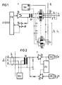
- Fig. 1 shows the main station H, a beacon control device.
- the main station H has a control device STH which is connected to a superordinate control computer LR.
- the control device STH is followed by a transmitting device SH and a receiving device EH.
- the output of the transmitting device SH of the main station leads to a transmitter ÜH.
- the two wires A and B of the transmission line ÜL are connected to the transformer UH via two matching resistors RA1 and RB1, each leading to a substation U1 to Un.
- Throttles DR1 are connected in parallel with the matching resistors RA and RB.
- the inductive resistance of these chokes DR1 which are each provided for a transmission line to the respective substation, is large compared to the matching resistances RA, RB lying parallel to it.
- a power supply device SVH is arranged in the main station, which leads to the respective C-wire of the transmission line with the zero potential.
- the live output of the power supply device SVH, labeled + U is connected to the center tap of the secondary winding of the transformer UH.
- the receiving device EH of the main station is connected to the primary winding of the transmitter UH.
- the output of the receiving device EH leads to the control device STH. This controls the receiving device EH of the main station via a control line.
- a throttle pair DR1 to DRn is provided for each transmission line ÜL1 to ÜLn.
- the matching resistors RA1 to RAn and RB to RBn are parallel to this.
- the information data coming from the master computer are transmitted in the main station H via the control device STH via the transmission device SH to the individual substations U1 to Un.
- the information sent by the substations U1 to Un is transmitted to the master computer LR via the receiving device EH of the main station and the control device STH of the main station.
- simultaneous transmission i.e. constant sending and receiving in the individual transmission gaps
- alternating sending and receiving i.e.
- the control device STH of the main station controls the transmitting and receiving device of the main station (SH and EH).
- the data received by the main station H via the transmission line ÜL are processed and sent to the actual beacon transmitter or data received by the beacon transmitter are transmitted to the main station.
- the substation U1 is shown in the block diagram in FIG.
- the data arrive from the main station H via the transmission line ÜL, which here has three wires A, B, C, to the substation U.
- the wires A and B lead to the primary winding of the transmitter ÜU of the substation.
- the wire C leads to the power supply device SVU of the substation, and a line also leads from the center tap of the primary winding of the transformer ÜU to the power supply device SVU of the substation.
- the transformer Un From the transformer Un, the data from the main station H to the receiving device EU of the sub station U and from there on the one hand to the control device STU of the sub station and on the other hand to the transmitting unit of the beacon transmitter via the secondary winding.
- the beacon transmitter is an infrared transmitter IRS shown, which sends the information data to the portable motor vehicles via infrared light IR. From there, the beacon receiver also receives the received data via the infrared radiation IR and the infrared receiving device IRE, which arrive in the substation U1 at the transmitting device SU of the substation and from there via the transmitter ÜU and the transmission line UL to the main station H. Both the receiving device EU and the transmitting device SU of the substation U are controlled by the control device STU, as described above and will be explained in more detail using further exemplary embodiments.
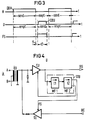
- FIG. 3 which represents a time diagram for an alternating dialog traffic, explains the transmission method for the information data.
- the main station H sends out data blocks DBH, switches to reception after sending out a data block DBH, during which time the substation U in turn sends its data block DBH to the main station H. Then the sub station U is again ready to receive the data block DBH of the main station H.
- This is illustrated in the first two diagrams.
- a time diagram is correspondingly shown for the release signal FS, which controls the transmission device (SU) of the substation U in this transmission method, namely the alternate transmission and reception.
- the control device of the substation is designed accordingly, as illustrated in FIG.
- the sub-station U which is connected to the transmission line UL via the transformer UU.
- the received signals lead from the transmitter UU to the receiving device EU of the substation U and from there to the control device STU and at the same time to the infrared transmitter IRS.
- the received signals from the infrared receiving device IRE go to the transmitting device SU of the substation and from there to the transmitter UU and then to the transmission line ÜL.
- the transmission device SU is acted upon by the control device STU with the release signal FS.
- the transmission information of the main station is divided into individual data blocks DBH.
- the main station is switched to receive between these transmitted data blocks, so that the substations can send their feedback DBU in these gaps.
- the data blocks are transmitted in the form of HDLC (High Level Data Link Control) protocols, whereby the operating mode NRZI (Never Retum to Zero Invert) is provided.
- An essential characteristic here is that the content of the data blocks is made transparent by inserting or leaving out zero bits, and that a signal change takes place after no more than six transmission clocks.
- the end of a data block DB can therefore only be recognized after seven transmit clocks at the earliest.
- the control device STU of the substation U is designed accordingly for this transmission method. It therefore has a first delay element, for example a retriggerable monoflop MF1 with a delay time of t1, which is continuously retriggered while the main station (H) is transmitting. Since the end of a data block DB can be recognized at the earliest after seven transmission clocks, the delay time t1 of the monoflop MF1 is selected to be equal to or greater than seven transmission clocks.
- the output of the monoflop MF1 triggers a second delay element, the monoflop MF2, with a delay time of t2.
- the receiving device EU of the substation U is blocked and the transmitting device SU of the substation U is released (release signal FS).
- release signal FS release signal FS
- a possible feedback from the substation U to the main station H can thus take place during the delay time t2 of the second monofiop MF2, as shown in the time diagram in FIG.
- the times t1 and t2 entered there correspond to the delay times of the first and second monoflops MF1 and MF2 in FIG.
- the first diagram shows the data blocks sent by the main station H, which are sent, for example, in a pulse-pause ratio of 1: 3.
- the main station H constantly sends to the sub-stations and the feedback from the sub-stations U to the main station takes place during the pulse pauses.
- the signal detection for the detection of a block end BE is shown under the time diagram of the transmission signals of the main station H and the transmission signals of the substation U. Below this, a time diagram is shown, which shows a section of the transmission signals of the main station and the substation.
- each sub-station In order to be able to transmit transmission signals from the sub-station of the main station in the pulse pauses of the constantly transmitting main station, each sub-station must derive its transmission signals from the received transmission signals of the main station with a corresponding control device, as is shown in FIG. 6 as an example.
- the substation transmits with a time delay or phase shift between the transmission pulses from the main station, as can be seen from the time diagrams in FIG. 5, lower half.
- the time diagram labeled ASU shows the signals that the astable flip-flop in the substation U (FIG. 6) derives from the transmission signals of the main station H for controlling the transmission device of the substation.
- TH is the time range of possible transmission pulses from the main station.
- tU is the time range of possible transmission pulses from the substation.
- the transmission signal from the main station consists of pulses, preferably with a pulse-pause ratio of 1: 3.
- the transmission signal of the substations is synchronized by the transmission signal of the main station and is delayed or out of phase between two possible transmission pulses of the main station.
- the transmission information of the main station can also be divided into individual data blocks, which, however, can also be strung together without gaps.
- the control unit of the main station changes continuously between the Sen operating mode and receive, the transmission device of the main station always remains switched on, but the receiver of the main station is switched to operational only in the range of possible transmission pulses from the substation.
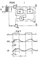
- the control device is designed accordingly for this information transmission method, as shown in FIG.
- FIG. 6 shows a control device STU of the substation U possible for this method in the block diagram.
- the substation U is connected to the transmission line ÜL via the transformer ÜU of the substation.
- the receiving device EU of the substation Via the receiving device EU of the substation, the received data on the one hand reach an astable flip-flop ASU and a block end detection device BE and on the other hand to the infrared transmitter IRS.
- the data received by the infrared receiver IRE reach the transmitting device SU of the substation and from there via the transmitter UU and the transmission line ÜL to the main station.
- the control device STU of the substation U controls the receiving and transmitting device EU and SU of the substation U in accordance with the transmission methods explained above.
- the individual transmission pulses from the main station synchronize the astable multivibrator ASU.
- the block end detection device BE releases the transmission device SU of the substation via the AND gate, which is also acted upon by the astable multivibrator ASU.
- the receiving device EU of the substation is blocked.
- the receiving device EU of the substation is then released again, while the receiving device SU of the substation is blocked while receiving the information data from the main station.
- LPSH shows the logic level of the transmission signal in front of the transmission device SH of the main station.
- the shortest bit sequence time is designated tB.
- tB In order to avoid overcoupling between the individual wires of the transmission line, the rising and falling edges are ground.
- the rise and fall times of the transmission signal have a time constant S. This is shown in the second diagram, which is designated SSÜH and shows the transmission signals at the transmitter ÜH of the main station.
- the time constant t E of the receive signals of the substation is obtained in connection with the line capacity of the transmission line, which may fluctuate greatly over a longer period of time, where ⁇ - E max - 0.6. tB guarantees interference-free reception in the substation.
- the reception signals of the substation are also shown in the diagram and designated ESU as they occur at the entrance of the reception device EU of the substation.
Landscapes
- Engineering & Computer Science (AREA)
- Signal Processing (AREA)
- Computer Networks & Wireless Communication (AREA)
- Life Sciences & Earth Sciences (AREA)
- Atmospheric Sciences (AREA)
- Physics & Mathematics (AREA)
- General Physics & Mathematics (AREA)
- Selective Calling Equipment (AREA)
- Circuits Of Receivers In General (AREA)
- Traffic Control Systems (AREA)
Claims (4)
caractérisé par le fait que dans chaque poste principal (H) il est prévu un dispositif d'émission et un dispositif de réception (SH, EH), qui sont raccordés à un translateur (ÙH) raccordé à une ligne de transmission (ÜL), un dispositif de commande (STH), qui est relié, d'une part, aux dispositifs d'émission et de réception (SH, EH), et, d'autre part, à un calculateur pilote (LR), et un dispositif (SVH) d'alimentation en courant à distance pour les postes secondaires (U1 à Un),
Priority Applications (1)
| Application Number | Priority Date | Filing Date | Title |
|---|---|---|---|
| AT86111087T ATE54521T1 (de) | 1985-08-14 | 1986-08-11 | Anordnung fuer ein verkehrsleit- und informationssystem. |
Applications Claiming Priority (2)
| Application Number | Priority Date | Filing Date | Title |
|---|---|---|---|
| DE3529166 | 1985-08-14 | ||
| DE3529166 | 1985-08-14 |
Publications (2)
| Publication Number | Publication Date |
|---|---|
| EP0218046A1 EP0218046A1 (fr) | 1987-04-15 |
| EP0218046B1 true EP0218046B1 (fr) | 1990-07-11 |
Family
ID=6278509
Family Applications (1)
| Application Number | Title | Priority Date | Filing Date |
|---|---|---|---|
| EP86111087A Expired - Lifetime EP0218046B1 (fr) | 1985-08-14 | 1986-08-11 | Dispositif pour un système de guidage d'informations de trafic |
Country Status (3)
| Country | Link |
|---|---|
| EP (1) | EP0218046B1 (fr) |
| AT (1) | ATE54521T1 (fr) |
| DE (1) | DE3672550D1 (fr) |
Families Citing this family (3)
| Publication number | Priority date | Publication date | Assignee | Title |
|---|---|---|---|---|
| DE3769726D1 (de) * | 1986-08-13 | 1991-06-06 | Siemens Ag | Verkehrsleit- und informationssystem. |
| ATE160459T1 (de) * | 1992-07-02 | 1997-12-15 | Siemens Ag | Anordnung zur datenübertragung |
| US5450024A (en) * | 1994-01-19 | 1995-09-12 | Alcatel Network Systems, Inc. | ECL to CMOS signal converter circuit including toggle-fault detection |
Family Cites Families (5)
| Publication number | Priority date | Publication date | Assignee | Title |
|---|---|---|---|---|
| DE2346984B2 (de) * | 1973-09-18 | 1975-10-30 | Siemens Ag, 1000 Berlin Und 8000 Muenchen | Verfahren zur Übertragung von digitalen Informationen eines Zeitmultip lexfernmeldenetzes |
| JPS5321963B2 (fr) * | 1973-11-12 | 1978-07-06 | ||
| DE2507803C1 (de) * | 1975-02-24 | 1980-04-03 | Siemens Ag | Schaltungsanordnung zur Steuerung des Schluesselbetriebes bei prozedurgesteuerten Halbduplex-Datenuebertragungsanlagen |
| US4388716A (en) * | 1979-11-15 | 1983-06-14 | Fuji Electric Co., Ltd. | Two-way transmission system |
| DE3304451C1 (de) * | 1983-02-09 | 1990-02-15 | Siemens AG, 1000 Berlin und 8000 München | Verfahren und Einrichtung zur bidirektionalen Informationsübertragung zwischen einer stationären Hauptstation und mehreren mobilen Unterstationen |
-
1986
- 1986-08-11 DE DE8686111087T patent/DE3672550D1/de not_active Expired - Lifetime
- 1986-08-11 EP EP86111087A patent/EP0218046B1/fr not_active Expired - Lifetime
- 1986-08-11 AT AT86111087T patent/ATE54521T1/de not_active IP Right Cessation
Also Published As
| Publication number | Publication date |
|---|---|
| ATE54521T1 (de) | 1990-07-15 |
| EP0218046A1 (fr) | 1987-04-15 |
| DE3672550D1 (de) | 1990-08-16 |
Similar Documents
| Publication | Publication Date | Title |
|---|---|---|
| EP1483819B1 (fr) | Systeme de commande pour ligne secteur | |
| EP0218046B1 (fr) | Dispositif pour un système de guidage d'informations de trafic | |
| EP0613259B1 (fr) | Dispositif pour communication continue dans un système de transmission à câble rayonnant | |
| DE2402932C2 (de) | Einrichtung zur linienförmigen Fahrzeugbeeinflussung | |
| DE2850208C2 (de) | Anordnung von jeweils aus Sender/ Empfängerkombinationen bestehenden Meldestationen an Straßenkreuzungen zum Zwecke der Bevorrechtigung bestimmter Bedarfsträger | |
| DE3150380C2 (fr) | ||
| EP0256483B1 (fr) | Système pour guider et informer le trafic | |
| DE3304451C1 (de) | Verfahren und Einrichtung zur bidirektionalen Informationsübertragung zwischen einer stationären Hauptstation und mehreren mobilen Unterstationen | |
| WO2002019566A1 (fr) | Procede et dispositif permettant de transmettre des informations entre des parties individuelles d'un train | |
| DE3421493C2 (fr) | ||
| EP0094660B1 (fr) | Réseau local pour vitesses de transmission élevées | |
| DE3043461A1 (de) | Verfahren zur entfernungsmessung zwischen einem spurgebundenen fahrzeug und einer ortsfesten station | |
| DE3124068A1 (de) | "einrichtung zur ortung und zur datenuebertragung von und/oder zu fahrzeugen" | |
| DE1530358B2 (de) | Ei nrichtung zur zentralen Lenkung des Verkehrs von Fahrzeugen in einem Streckennetz | |
| DE3236364C2 (fr) | ||
| AT254256B (de) | System zur Sicherung und Steuerung spurgebundener Fahrzeuge, insbesondere Schienenfahrzeuge | |
| EP1026062B1 (fr) | Procédé d'évaluation de signaux de contact des rails | |
| EP0495561B1 (fr) | Dispositif pour la transmission d'informations à la commande de train | |
| DE2743507A1 (de) | Verfahren zur reduzierung der telegrammfehlerrate bei der datenuebertragung ueber linienleiter | |
| DE2703931A1 (de) | Einrichtung zur datenuebertragung und entfernungsmessung zwischen schienenfahrzeugen und einer ortsfesten station | |
| DE1605414B2 (de) | Einrichtung zum warnen von rotten | |
| DE1605414C3 (de) | Einrichtung zum Warnen von Rotten | |
| EP0121666B1 (fr) | Méthode et dispositif pour la surveillance d'amplificateurs intermédiaires | |
| AT390535B (de) | Verfahren zur synchronisierung von pulsmodulierten signalen | |
| EP0310705A1 (fr) | Système de radio transmission |
Legal Events
| Date | Code | Title | Description |
|---|---|---|---|
| PUAI | Public reference made under article 153(3) epc to a published international application that has entered the european phase |
Free format text: ORIGINAL CODE: 0009012 |
|
| AK | Designated contracting states |
Kind code of ref document: A1 Designated state(s): AT BE CH DE FR GB LI NL |
|
| 17P | Request for examination filed |
Effective date: 19871010 |
|
| 17Q | First examination report despatched |
Effective date: 19890914 |
|
| GRAA | (expected) grant |
Free format text: ORIGINAL CODE: 0009210 |
|
| AK | Designated contracting states |
Kind code of ref document: B1 Designated state(s): AT BE CH DE FR GB LI NL |
|
| REF | Corresponds to: |
Ref document number: 54521 Country of ref document: AT Date of ref document: 19900715 Kind code of ref document: T |
|
| REF | Corresponds to: |
Ref document number: 3672550 Country of ref document: DE Date of ref document: 19900816 |
|
| ET | Fr: translation filed | ||
| GBT | Gb: translation of ep patent filed (gb section 77(6)(a)/1977) | ||
| PLBE | No opposition filed within time limit |
Free format text: ORIGINAL CODE: 0009261 |
|
| STAA | Information on the status of an ep patent application or granted ep patent |
Free format text: STATUS: NO OPPOSITION FILED WITHIN TIME LIMIT |
|
| 26N | No opposition filed | ||
| PGFP | Annual fee paid to national office [announced via postgrant information from national office to epo] |
Ref country code: GB Payment date: 19920717 Year of fee payment: 7 |
|
| PGFP | Annual fee paid to national office [announced via postgrant information from national office to epo] |
Ref country code: AT Payment date: 19920722 Year of fee payment: 7 |
|
| PGFP | Annual fee paid to national office [announced via postgrant information from national office to epo] |
Ref country code: BE Payment date: 19920814 Year of fee payment: 7 |
|
| PGFP | Annual fee paid to national office [announced via postgrant information from national office to epo] |
Ref country code: FR Payment date: 19920821 Year of fee payment: 7 |
|
| PGFP | Annual fee paid to national office [announced via postgrant information from national office to epo] |
Ref country code: NL Payment date: 19920831 Year of fee payment: 7 |
|
| PGFP | Annual fee paid to national office [announced via postgrant information from national office to epo] |
Ref country code: DE Payment date: 19921023 Year of fee payment: 7 |
|
| PGFP | Annual fee paid to national office [announced via postgrant information from national office to epo] |
Ref country code: CH Payment date: 19921120 Year of fee payment: 7 |
|
| PG25 | Lapsed in a contracting state [announced via postgrant information from national office to epo] |
Ref country code: GB Effective date: 19930811 Ref country code: AT Effective date: 19930811 |
|
| PG25 | Lapsed in a contracting state [announced via postgrant information from national office to epo] |
Ref country code: LI Effective date: 19930831 Ref country code: CH Effective date: 19930831 Ref country code: BE Effective date: 19930831 |
|
| BERE | Be: lapsed |
Owner name: SIEMENS A.G. Effective date: 19930831 |
|
| PG25 | Lapsed in a contracting state [announced via postgrant information from national office to epo] |
Ref country code: NL Effective date: 19940301 |
|
| GBPC | Gb: european patent ceased through non-payment of renewal fee |
Effective date: 19930811 |
|
| NLV4 | Nl: lapsed or anulled due to non-payment of the annual fee | ||
| PG25 | Lapsed in a contracting state [announced via postgrant information from national office to epo] |
Ref country code: FR Effective date: 19940429 |
|
| REG | Reference to a national code |
Ref country code: CH Ref legal event code: PL |
|
| PG25 | Lapsed in a contracting state [announced via postgrant information from national office to epo] |
Ref country code: DE Effective date: 19940503 |
|
| REG | Reference to a national code |
Ref country code: FR Ref legal event code: ST |