EP0218082B1 - Sliding gate valves and methods of operating them - Google Patents
Sliding gate valves and methods of operating them Download PDFInfo
- Publication number
- EP0218082B1 EP0218082B1 EP86111937A EP86111937A EP0218082B1 EP 0218082 B1 EP0218082 B1 EP 0218082B1 EP 86111937 A EP86111937 A EP 86111937A EP 86111937 A EP86111937 A EP 86111937A EP 0218082 B1 EP0218082 B1 EP 0218082B1
- Authority
- EP
- European Patent Office
- Prior art keywords
- refractory
- plate
- casing
- structure according
- nozzle
- Prior art date
- Legal status (The legal status is an assumption and is not a legal conclusion. Google has not performed a legal analysis and makes no representation as to the accuracy of the status listed.)
- Expired - Lifetime
Links
Images



Classifications
-
- B—PERFORMING OPERATIONS; TRANSPORTING
- B22—CASTING; POWDER METALLURGY
- B22D—CASTING OF METALS; CASTING OF OTHER SUBSTANCES BY THE SAME PROCESSES OR DEVICES
- B22D41/00—Casting melt-holding vessels, e.g. ladles, tundishes, cups or the like
- B22D41/08—Casting melt-holding vessels, e.g. ladles, tundishes, cups or the like for bottom pouring
-
- F—MECHANICAL ENGINEERING; LIGHTING; HEATING; WEAPONS; BLASTING
- F27—FURNACES; KILNS; OVENS; RETORTS
- F27D—DETAILS OR ACCESSORIES OF FURNACES, KILNS, OVENS OR RETORTS, IN SO FAR AS THEY ARE OF KINDS OCCURRING IN MORE THAN ONE KIND OF FURNACE
- F27D3/00—Charging; Discharging; Manipulation of charge
- F27D3/15—Tapping equipment; Equipment for removing or retaining slag
- F27D3/1509—Tapping equipment
-
- B—PERFORMING OPERATIONS; TRANSPORTING
- B22—CASTING; POWDER METALLURGY
- B22D—CASTING OF METALS; CASTING OF OTHER SUBSTANCES BY THE SAME PROCESSES OR DEVICES
- B22D41/00—Casting melt-holding vessels, e.g. ladles, tundishes, cups or the like
- B22D41/14—Closures
- B22D41/22—Closures sliding-gate type, i.e. having a fixed plate and a movable plate in sliding contact with each other for selective registry of their openings
- B22D41/24—Closures sliding-gate type, i.e. having a fixed plate and a movable plate in sliding contact with each other for selective registry of their openings characterised by a rectilinearly movable plate
Definitions
- This invention relates to refractory plate structures for use in a sliding gate valve assembly for controlling the flow of molten metal from the pour opening of a vessel
- a housing mounted on said vessel a stationary refractory plate in said housing having an orifice in open communication with said vessel pour opening, a slide carrier movably mounted in said housing, an orificed refractory slide gate in said housing and urged into pressure-sealing, face-to-face relation with said stationary plate, and drive means for moving said slide carrier and said slide plate within said housing to place the orifice therein into and out of registry with the orifice in said stationary plate and wherein said refractory plates are held in metal casings each metal casing having an orifice in its base in alignment with the orifice in the respective refractory plate and a peripheral edge upstanding from the base.
- the refractory material in such structures is subject to substantial erosion in use, and the plate structures require frequent replacement.
- a refractory plate structure in which a preformed refractory plate is inserted into a sheet metal casing and is fixed therein by a layer of mortar.
- the base of the sheet metal casing is formed of a network of metal strips defining several holes through which the refractory plate is exposed to be directly supported by the frame.
- a refractory plate structure in which drawbacks associated with a layer of mortar are eliminated by forming the refractory plate in situ.
- the refractory plate is cast into the metal casing which substantially encases the refractory plate, except for the sliding surface thereof.
- the present invention has for its aim to provide a refractory plate structure with a metal casing which, unlike the metal casings of the prior art structures, is adapted to be used to remanufacture a refractory plate structure after the refractory plate has completed its service lifetime, and a refractory plate structure in accordance with the invention is characterised in that the metal casing having the refractory plate cast therein is formed with at least one additional opening in its base for reception of a knock-out tool for removal of the cast refractory material from said casing when spent, and that the casing is thereby re-usable.
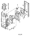
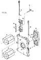
- valve assembly illustrated in Figures 1, 1A, 2L and 2R and the heat shield and nozzle assembly illustrated in Figures 19 and 20, are fully described in the specification of the parent European Patent Application publication number 0120695 A2 to which reference is hereby directed.
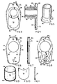
- the slide gate assembly is shown in Figures 3-11.
- a slide gate frame casing 60 including a base having an outer skirt 61 upturned from the base and a collector pad ring 62, a bearing surface for spring pads 35, receive and mount the slide gate collector 29.
- an insert pad ring 64 also a bearing surface for spring pads 35, is provided in the slide gate frame casing 60 and interiorly thereof provision is made for a hole 65 that extends through the casting base. This hole is operative as a knock out hole for reception of a mandrel, or similar tool, to facilitate removal of the refractory elements of the plate during remanufacture.
- the casing further contains a plurality of threaded holes 66 for reception of the threaded ends of pins (not shown) for positioning the fired inserts 70 during pouring of the monolithic material during fabrication of the plate as described hereafter.
- Inner ribs 68 and outer ribs 69 are provided interiorly of and adjacent to the insert pad ring 64 to give additional strength.
- the insert 70 shown in Figures 3 and 10 is a preformed high duty refractory member that has a collector crotch 71 which engages the collector rim 72 of a similar preformed high duty refractory member that lines the flow opening through the slide gate.
- the collector rim flat 74 and the insert 70 are arranged in a bed of monolithic refractory to be in coplanar disposition on the surface of the gate 21 and are formed of an erosion and/or abrasion resistant material such as zirconium oxide or aluminium oxide since they are the elements which are in contact with molten metal.
- the collector tube 75 (see Figures 4 and 9) encloses the monolithic bed 80 and is provided with threads 76 for threadedly engaging the slide gate frame casing 60.
- a portion of the monolithic material 80 extends beyond the end of the tube 75 forming a refractory collector end 84. That portion of the short end 85 of the sliding gate 21 presents a face of monolithic material which does not come in contact with the molten metal.
- the side flats 81 and end flats 82 formed on the skirt 61 of the slide gate frame casing 60.
- lifting holes or recesses 86 may be bored in the side flats 81 for reception of a mechanical lifting apparatus to assist in manipulating the plate.
- the stationary plate is shown in Figures 12-17 inclusive.
- the stationary plate 20 is symmetrical about the metal flow opening, even though the sliding gate 21 is asymmetrical about the flow opening therethrough.
- the metal stationary plate casing 90 is provided with a peripheral skirt 91 upstanding from its base.
- an orifice insert 92 is disposed in a bed of monolithic refractory 93 with an annular insert lock groove 94 so positioned for interlocking the insert in the refractory bed 93 within the frame 90.
- Knockout holes 95 are provided at opposed positions in the base of frame 90, and each is formed with an inturned lock ring 96 that serves to anchor the refractory bed 93 within the frame.
- a well nozzle stepped seat 98 is provided centrally of the stationary plate 90, and terminates in one face of the stationary plate orifice insert 92.
- Threaded bores 99 are provided in the reinforcing rings 97 which surround the knockout holes 95. The bores 99 are threaded to receive funnels useful in casting monolithic refractory 93 into the stationary plate 20.
- a preferred construction of well nozzle 19 is provided which rests atop the well nozzle seat 98 within the stationary plate frame 90.
- a locking assembly 105 is provided to secure the well nozzle 19 to the stationary plate 20. More specifically, a clamp washer 106 is secured by means of mount threads 107 in the stationary plate 90 through the medium of the washer mount screw 108. The washer 106 then is secured into the crescent-shaped recess that forms a washer lock 109 in the refractory of the well nozzle 19.
- Such locking arrangements are disposed on circumferential spacing about the periphery of the nozzle 19. Once this locking has taken place, the well nozzle 19 becomes fixed to the stationary plate frame 90 so that it can be installed in the valve upon installation of the stationary plate.
- the taper 110 on the block nozzle 19 is accurately secured in mating engagement with a mating taper 111 (see Figure 1) in the outer tap hole block 18 within the refractory 14 of the furnace 12 thereby avoiding sealing problems that would otherwise be occasioned by a blind assembly operation.
- the alternative construction of the well nozzle 19 is shown in Figure 21, where the alternate refractory nozzle structure 104 is encased within a metal well nozzle frame 100, and includes a well nozzle ring 101 forming a shoulder which is lockingly engaged within a bored opening in the mounting plate, and secured in position by means of the well nozzle mortar 102, again as shown in Figure 21.
- the top plate is secured in place on the mounting plate 40 by positioning members that include top plate retaining pins 42 and restraint 43.
- stationary plate 20 and slide gates 21 are worn, they may be remanufactured and their respective frames reclaimed.
- a mandrel or press can engage the monolithic collector end 84, while at the same time a mandrel is inserted in the knockout hole 65. The combined pressures removes the collector insert 29 and the face insert 70. Thereafter by tapping or shaking, the balance of the monolithic cast material 80 may be removed.
- the casting spacer mount 66 of the sliding gate 21 as shown in Figures 6 and 7 permits the insertion of a spacer to support the insert 70.
- the four circumferentially spaced spacer bores 99 about each reinforcing ring 97 in the top plate frame 90 are adapted for connection with a pouring spout that serve as sprews for supplying the castable material to the plate frame during fabrication.
- Lifting holes 87 may be optionally provided in the stationary plate in the same fashion as the holes 86 are provided in the sliding gate.
- the furnace valve 10 as shown is modified by means of an adaptor 11 to accommodate it to a furnace 12 in which the side tap is at an angle to the vertical.
- Lifting eyes 44 are provided on the frame assembly 36 so that the entire valve 10 can be removed.
- the hinge assembly 45 and the latch assembly 50 may be modified and simplified to a simple clamp.
- the hinge assembly 45 and latch assembly 50 are shown to illustrate that the valve can be used in either mode when the refractory is replaced while the valve 10 is on the furnace 12, or in the event it is removed.
Landscapes
- Engineering & Computer Science (AREA)
- Mechanical Engineering (AREA)
- General Engineering & Computer Science (AREA)
- Casting Support Devices, Ladles, And Melt Control Thereby (AREA)
- Furnace Charging Or Discharging (AREA)
- Sliding Valves (AREA)
- Details Of Valves (AREA)
- Coupling Device And Connection With Printed Circuit (AREA)
- Adjustment Of The Magnetic Head Position Track Following On Tapes (AREA)
- Glass Compositions (AREA)
- Control Of The Air-Fuel Ratio Of Carburetors (AREA)
- Cookers (AREA)
- Electrically Driven Valve-Operating Means (AREA)
- Discharge Heating (AREA)
- Mechanically-Actuated Valves (AREA)
- Fluid-Driven Valves (AREA)
- Fats And Perfumes (AREA)
- Vending Machines For Individual Products (AREA)
- Check Valves (AREA)
- Means For Warming Up And Starting Carburetors (AREA)
- Moulds For Moulding Plastics Or The Like (AREA)
Priority Applications (1)
| Application Number | Priority Date | Filing Date | Title |
|---|---|---|---|
| AT86111937T ATE91929T1 (de) | 1983-03-24 | 1984-03-26 | Flachschieber und verfahren zur betaetigung. |
Applications Claiming Priority (2)
| Application Number | Priority Date | Filing Date | Title |
|---|---|---|---|
| US06/478,218 US4474362A (en) | 1983-03-24 | 1983-03-24 | Valve and method and components thereof |
| US478218 | 1983-03-24 |
Related Parent Applications (2)
| Application Number | Title | Priority Date | Filing Date |
|---|---|---|---|
| EP84302006A Division-Into EP0120695B1 (en) | 1983-03-24 | 1984-03-26 | Sliding gate valves and methods of operating them |
| EP84302006A Division EP0120695B1 (en) | 1983-03-24 | 1984-03-26 | Sliding gate valves and methods of operating them |
Publications (2)
| Publication Number | Publication Date |
|---|---|
| EP0218082A1 EP0218082A1 (en) | 1987-04-15 |
| EP0218082B1 true EP0218082B1 (en) | 1993-07-28 |
Family
ID=23899009
Family Applications (3)
| Application Number | Title | Priority Date | Filing Date |
|---|---|---|---|
| EP86111937A Expired - Lifetime EP0218082B1 (en) | 1983-03-24 | 1984-03-26 | Sliding gate valves and methods of operating them |
| EP86111932A Expired - Lifetime EP0218081B1 (en) | 1983-03-24 | 1984-03-26 | Sliding gate valves and methods of operating them |
| EP84302006A Expired EP0120695B1 (en) | 1983-03-24 | 1984-03-26 | Sliding gate valves and methods of operating them |
Family Applications After (2)
| Application Number | Title | Priority Date | Filing Date |
|---|---|---|---|
| EP86111932A Expired - Lifetime EP0218081B1 (en) | 1983-03-24 | 1984-03-26 | Sliding gate valves and methods of operating them |
| EP84302006A Expired EP0120695B1 (en) | 1983-03-24 | 1984-03-26 | Sliding gate valves and methods of operating them |
Country Status (14)
| Country | Link |
|---|---|
| US (1) | US4474362A (2) |
| EP (3) | EP0218082B1 (2) |
| JP (4) | JP2575609B2 (2) |
| KR (1) | KR910008028B1 (2) |
| AT (3) | ATE91929T1 (2) |
| AU (3) | AU578412B2 (2) |
| BR (1) | BR8401362A (2) |
| CA (1) | CA1250428A (2) |
| DE (3) | DE3486039T2 (2) |
| ES (3) | ES530935A0 (2) |
| IN (1) | IN160949B (2) |
| MX (5) | MX160959A (2) |
| PH (1) | PH25474A (2) |
| ZA (1) | ZA842193B (2) |
Families Citing this family (8)
| Publication number | Priority date | Publication date | Assignee | Title |
|---|---|---|---|---|
| US4603842A (en) * | 1983-03-24 | 1986-08-05 | Flo-Con Systems, Inc. | Method of sliding gate valve operation |
| US4615471A (en) * | 1985-06-19 | 1986-10-07 | M. H. Detrich | Refractory plate and method for reinforcing |
| JPH05289Y2 (2) * | 1987-05-18 | 1993-01-06 | ||
| CA1321525C (en) * | 1987-06-18 | 1993-08-24 | Joseph John Tkac | Process for use in milling flour |
| LU88253A1 (fr) * | 1993-04-30 | 1994-12-01 | Wurth Paul Sa | Trou de coulée pour un four à cuve, notamment un haut fourneau |
| BE1013024A3 (fr) * | 1998-12-15 | 2001-08-07 | Internat Ind Engineering S A | Tube de coulee. |
| US7437409B2 (en) * | 2003-06-13 | 2008-10-14 | Microsoft Corporation | Limiting interaction between parties in a networked session |
| DE102004050701B3 (de) * | 2004-10-18 | 2006-04-06 | Refractory Intellectual Property Gmbh & Co. Kg | Abstichrohr für ein metallurgisches Schmelzgefäß |
Citations (1)
| Publication number | Priority date | Publication date | Assignee | Title |
|---|---|---|---|---|
| GB2006411A (en) * | 1977-10-17 | 1979-05-02 | Gen Refractories Co | Slide gate and method for manufacture |
Family Cites Families (18)
| Publication number | Priority date | Publication date | Assignee | Title |
|---|---|---|---|---|
| US3613965A (en) * | 1969-06-25 | 1971-10-19 | United States Steel Corp | Operating and loading mechanism for slidable gates |
| US3831825A (en) * | 1969-07-25 | 1974-08-27 | Didier Werke Ag | Sliding valve for a container of liquid smelt provided with a lip |
| US4063668A (en) * | 1971-06-07 | 1977-12-20 | United States Steel Corporation | Ladle gate valve |
| US3918613A (en) * | 1973-03-01 | 1975-11-11 | United States Steel Corp | Sliding gate having selectively operable gas line for porous plug |
| US3866806A (en) * | 1973-03-01 | 1975-02-18 | United States Steel Corp | Operating mechanism for slidable gates and method of operating slide gate |
| US3841539A (en) * | 1973-03-01 | 1974-10-15 | United States Steel Corp | Collector nozzle for slidable gates |
| GB1492533A (en) * | 1973-11-23 | 1977-11-23 | Flogates Ltd | Pouring of metals |
| NL7416416A (nl) * | 1973-12-21 | 1975-06-24 | Zimmermann & Jansen Gmbh | Schuifafsluiting voor een gietpan voor vloeibaar metaal. |
| US4000837A (en) * | 1973-12-21 | 1977-01-04 | United States Steel Corporation | Sliding gate valves |
| IT1103846B (it) * | 1978-10-25 | 1985-10-14 | Sanac Spa | Scaricatore a cassetto perfezionato a tre posizioni |
| DE2918333A1 (de) * | 1979-05-07 | 1980-11-20 | Metacon Ag | Metallurgischer ofen |
| DE2918344A1 (de) * | 1979-05-07 | 1980-11-20 | Metacon Ag | Schieberverschluss fuer den abstichkanal eines metallurgischen ofens oder gefaesses |
| CH642880A5 (en) * | 1979-11-07 | 1984-05-15 | Metacon Ag | Drive for the slide gate nozzle of a metallurgical vessel |
| CH647966A5 (de) * | 1980-05-09 | 1985-02-28 | Stopinc Ag | Verschlussplatten-einheit fuer einen schiebeverschluss fuer metallurgische schmelzegefaesse. |
| JPS6226852Y2 (2) * | 1980-07-01 | 1987-07-09 | ||
| JPS5783398U (2) * | 1980-10-24 | 1982-05-22 | ||
| CH653933A5 (de) * | 1981-05-19 | 1986-01-31 | Stopinc Ag | Schiebeverschluss fuer schmelzegefaesse. |
| GB2117498B (en) * | 1982-04-01 | 1985-07-17 | Flogates Ltd | Sliding gate valves |
-
1983
- 1983-03-24 US US06/478,218 patent/US4474362A/en not_active Expired - Lifetime
-
1984
- 1984-03-15 CA CA000449674A patent/CA1250428A/en not_active Expired
- 1984-03-23 MX MX200750A patent/MX160959A/es unknown
- 1984-03-23 MX MX018504A patent/MX172012B/es unknown
- 1984-03-23 IN IN257/DEL/84A patent/IN160949B/en unknown
- 1984-03-23 KR KR1019840001507A patent/KR910008028B1/ko not_active Expired
- 1984-03-23 MX MX3724A patent/MX160956A/es unknown
- 1984-03-23 BR BR8401362A patent/BR8401362A/pt not_active IP Right Cessation
- 1984-03-23 PH PH30514A patent/PH25474A/en unknown
- 1984-03-23 ES ES530935A patent/ES530935A0/es active Granted
- 1984-03-23 AU AU26072/84A patent/AU578412B2/en not_active Ceased
- 1984-03-23 MX MX3723A patent/MX160955A/es unknown
- 1984-03-23 JP JP59055950A patent/JP2575609B2/ja not_active Expired - Fee Related
- 1984-03-23 MX MX018505A patent/MX167785B/es unknown
- 1984-03-23 ZA ZA842193A patent/ZA842193B/xx unknown
- 1984-03-26 AT AT86111937T patent/ATE91929T1/de not_active IP Right Cessation
- 1984-03-26 DE DE8686111932T patent/DE3486039T2/de not_active Expired - Lifetime
- 1984-03-26 AT AT84302006T patent/ATE30076T1/de not_active IP Right Cessation
- 1984-03-26 EP EP86111937A patent/EP0218082B1/en not_active Expired - Lifetime
- 1984-03-26 DE DE86111937T patent/DE3486186T2/de not_active Expired - Lifetime
- 1984-03-26 EP EP86111932A patent/EP0218081B1/en not_active Expired - Lifetime
- 1984-03-26 AT AT86111932T patent/ATE84456T1/de not_active IP Right Cessation
- 1984-03-26 DE DE8484302006T patent/DE3466590D1/de not_active Expired
- 1984-03-26 EP EP84302006A patent/EP0120695B1/en not_active Expired
-
1985
- 1985-04-01 ES ES1985285796U patent/ES285796Y/es not_active Expired
- 1985-04-01 ES ES541828A patent/ES8605629A1/es not_active Expired
-
1987
- 1987-06-29 AU AU74934/87A patent/AU597677B2/en not_active Ceased
- 1987-06-29 AU AU74935/87A patent/AU597678B2/en not_active Ceased
-
1996
- 1996-06-19 JP JP8158227A patent/JP2778948B2/ja not_active Expired - Lifetime
- 1996-06-19 JP JP8158226A patent/JP2778947B2/ja not_active Expired - Lifetime
- 1996-06-19 JP JP8158225A patent/JP2860284B2/ja not_active Expired - Fee Related
Patent Citations (1)
| Publication number | Priority date | Publication date | Assignee | Title |
|---|---|---|---|---|
| GB2006411A (en) * | 1977-10-17 | 1979-05-02 | Gen Refractories Co | Slide gate and method for manufacture |
Also Published As
Similar Documents
| Publication | Publication Date | Title |
|---|---|---|
| CA1043073A (en) | Pouring of molten metals | |
| US4327847A (en) | Sliding gate nozzles | |
| GB2213412A (en) | Refractory valve plate for sliding gate valve | |
| US6568571B2 (en) | Exchangeable continuous casting nozzle | |
| EP0218081B1 (en) | Sliding gate valves and methods of operating them | |
| US10300525B2 (en) | Molten metal filtration device | |
| GB2163375A (en) | Valve | |
| US4314659A (en) | Rotary valve | |
| US4445262A (en) | Procedure for rebuilding the movable plate in the pouring valve of a ladle | |
| GB2023784A (en) | Gate valve for ladles | |
| US4603842A (en) | Method of sliding gate valve operation | |
| WO1998042465A1 (en) | Refractory pour tube with cast plate | |
| US4570908A (en) | Furnace valve | |
| US3980271A (en) | Pouring of molten metals | |
| EP0080248B1 (en) | Refractory components | |
| US4602729A (en) | Stationary plate and well nozzle for use in a sliding gate valve | |
| CA1260259A (en) | Stationary plate | |
| US4667937A (en) | Heat shield for sliding gate valve | |
| US4789085A (en) | Slide gate for a sliding gate valve | |
| GB2153977A (en) | Sliding gate valves | |
| KR910009052B1 (ko) | 슬라이딩 게이트 밸브 조립체용 내화 판 구조물 | |
| KR910009055B1 (ko) | 슬라이딩 게이트 밸브의 고정 밸브판-출탕구 노즐 조립체 |
Legal Events
| Date | Code | Title | Description |
|---|---|---|---|
| PUAI | Public reference made under article 153(3) epc to a published international application that has entered the european phase |
Free format text: ORIGINAL CODE: 0009012 |
|
| 17P | Request for examination filed |
Effective date: 19860915 |
|
| AC | Divisional application: reference to earlier application |
Ref document number: 120695 Country of ref document: EP |
|
| AK | Designated contracting states |
Kind code of ref document: A1 Designated state(s): AT BE CH DE FR GB IT LI LU NL SE |
|
| RAP1 | Party data changed (applicant data changed or rights of an application transferred) |
Owner name: USX ENGINEERS AND CONSULTANTS, INC. |
|
| 17Q | First examination report despatched |
Effective date: 19880811 |
|
| GRAA | (expected) grant |
Free format text: ORIGINAL CODE: 0009210 |
|
| AC | Divisional application: reference to earlier application |
Ref document number: 120695 Country of ref document: EP |
|
| AK | Designated contracting states |
Kind code of ref document: B1 Designated state(s): AT BE CH DE FR GB IT LI LU NL SE |
|
| REF | Corresponds to: |
Ref document number: 91929 Country of ref document: AT Date of ref document: 19930815 Kind code of ref document: T |
|
| ITF | It: translation for a ep patent filed | ||
| REF | Corresponds to: |
Ref document number: 3486186 Country of ref document: DE Date of ref document: 19930902 |
|
| ET | Fr: translation filed | ||
| EPTA | Lu: last paid annual fee | ||
| PLBE | No opposition filed within time limit |
Free format text: ORIGINAL CODE: 0009261 |
|
| STAA | Information on the status of an ep patent application or granted ep patent |
Free format text: STATUS: NO OPPOSITION FILED WITHIN TIME LIMIT |
|
| 26N | No opposition filed | ||
| EAL | Se: european patent in force in sweden |
Ref document number: 86111937.8 |
|
| REG | Reference to a national code |
Ref country code: GB Ref legal event code: IF02 |
|
| PGFP | Annual fee paid to national office [announced via postgrant information from national office to epo] |
Ref country code: SE Payment date: 20020305 Year of fee payment: 19 Ref country code: NL Payment date: 20020305 Year of fee payment: 19 Ref country code: AT Payment date: 20020305 Year of fee payment: 19 |
|
| PGFP | Annual fee paid to national office [announced via postgrant information from national office to epo] |
Ref country code: CH Payment date: 20020306 Year of fee payment: 19 |
|
| PGFP | Annual fee paid to national office [announced via postgrant information from national office to epo] |
Ref country code: LU Payment date: 20020320 Year of fee payment: 19 |
|
| PGFP | Annual fee paid to national office [announced via postgrant information from national office to epo] |
Ref country code: BE Payment date: 20020327 Year of fee payment: 19 |
|
| PGFP | Annual fee paid to national office [announced via postgrant information from national office to epo] |
Ref country code: FR Payment date: 20030304 Year of fee payment: 20 |
|
| PGFP | Annual fee paid to national office [announced via postgrant information from national office to epo] |
Ref country code: GB Payment date: 20030319 Year of fee payment: 20 |
|
| PG25 | Lapsed in a contracting state [announced via postgrant information from national office to epo] |
Ref country code: LU Free format text: LAPSE BECAUSE OF NON-PAYMENT OF DUE FEES Effective date: 20030326 Ref country code: AT Free format text: LAPSE BECAUSE OF NON-PAYMENT OF DUE FEES Effective date: 20030326 |
|
| PG25 | Lapsed in a contracting state [announced via postgrant information from national office to epo] |
Ref country code: SE Free format text: LAPSE BECAUSE OF NON-PAYMENT OF DUE FEES Effective date: 20030327 |
|
| PG25 | Lapsed in a contracting state [announced via postgrant information from national office to epo] |
Ref country code: LI Free format text: LAPSE BECAUSE OF NON-PAYMENT OF DUE FEES Effective date: 20030331 Ref country code: CH Free format text: LAPSE BECAUSE OF NON-PAYMENT OF DUE FEES Effective date: 20030331 Ref country code: BE Free format text: LAPSE BECAUSE OF NON-PAYMENT OF DUE FEES Effective date: 20030331 |
|
| PGFP | Annual fee paid to national office [announced via postgrant information from national office to epo] |
Ref country code: DE Payment date: 20030331 Year of fee payment: 20 |
|
| BERE | Be: lapsed |
Owner name: *USX ENGINEERS AND CONSULTANTS INC. Effective date: 20030331 |
|
| PG25 | Lapsed in a contracting state [announced via postgrant information from national office to epo] |
Ref country code: NL Free format text: LAPSE BECAUSE OF NON-PAYMENT OF DUE FEES Effective date: 20031001 |
|
| EUG | Se: european patent has lapsed | ||
| REG | Reference to a national code |
Ref country code: CH Ref legal event code: PL |
|
| NLV4 | Nl: lapsed or anulled due to non-payment of the annual fee |
Effective date: 20031001 |
|
| PG25 | Lapsed in a contracting state [announced via postgrant information from national office to epo] |
Ref country code: GB Free format text: LAPSE BECAUSE OF EXPIRATION OF PROTECTION Effective date: 20040325 |
|
| REG | Reference to a national code |
Ref country code: GB Ref legal event code: PE20 |