EP0218232A1 - Débitmètre à fil chaud pour l'air - Google Patents
Débitmètre à fil chaud pour l'air Download PDFInfo
- Publication number
- EP0218232A1 EP0218232A1 EP86113872A EP86113872A EP0218232A1 EP 0218232 A1 EP0218232 A1 EP 0218232A1 EP 86113872 A EP86113872 A EP 86113872A EP 86113872 A EP86113872 A EP 86113872A EP 0218232 A1 EP0218232 A1 EP 0218232A1
- Authority
- EP
- European Patent Office
- Prior art keywords
- air flow
- wire
- flow meter
- exothermic resistor
- hot wire
- Prior art date
- Legal status (The legal status is an assumption and is not a legal conclusion. Google has not performed a legal analysis and makes no representation as to the accuracy of the status listed.)
- Granted
Links
- BASFCYQUMIYNBI-UHFFFAOYSA-N platinum Chemical compound [Pt] BASFCYQUMIYNBI-UHFFFAOYSA-N 0.000 claims abstract description 29
- 239000011521 glass Substances 0.000 claims abstract description 16
- 229910052751 metal Inorganic materials 0.000 claims description 14
- 239000002184 metal Substances 0.000 claims description 14
- 239000000463 material Substances 0.000 claims description 13
- 238000004804 winding Methods 0.000 claims description 11
- 239000002253 acid Substances 0.000 claims description 3
- 238000000034 method Methods 0.000 claims description 2
- 230000008569 process Effects 0.000 claims description 2
- WABPQHHGFIMREM-UHFFFAOYSA-N lead(0) Chemical compound [Pb] WABPQHHGFIMREM-UHFFFAOYSA-N 0.000 claims 1
- WFKWXMTUELFFGS-UHFFFAOYSA-N tungsten Chemical compound [W] WFKWXMTUELFFGS-UHFFFAOYSA-N 0.000 claims 1
- 230000004044 response Effects 0.000 abstract description 9
- 230000001052 transient effect Effects 0.000 abstract description 6
- 230000008859 change Effects 0.000 abstract description 3
- 238000002485 combustion reaction Methods 0.000 description 8
- ZOKXTWBITQBERF-UHFFFAOYSA-N Molybdenum Chemical compound [Mo] ZOKXTWBITQBERF-UHFFFAOYSA-N 0.000 description 7
- 238000004519 manufacturing process Methods 0.000 description 4
- 238000005260 corrosion Methods 0.000 description 3
- 230000007797 corrosion Effects 0.000 description 3
- QAOWNCQODCNURD-UHFFFAOYSA-N Sulfuric acid Chemical compound OS(O)(=O)=O QAOWNCQODCNURD-UHFFFAOYSA-N 0.000 description 2
- 230000001133 acceleration Effects 0.000 description 2
- 238000010438 heat treatment Methods 0.000 description 2
- GRYLNZFGIOXLOG-UHFFFAOYSA-N Nitric acid Chemical compound O[N+]([O-])=O GRYLNZFGIOXLOG-UHFFFAOYSA-N 0.000 description 1
- 239000000919 ceramic Substances 0.000 description 1
- 239000011248 coating agent Substances 0.000 description 1
- 238000000576 coating method Methods 0.000 description 1
- 150000001875 compounds Chemical group 0.000 description 1
- 238000010276 construction Methods 0.000 description 1
- 238000005520 cutting process Methods 0.000 description 1
- 230000007423 decrease Effects 0.000 description 1
- 230000003247 decreasing effect Effects 0.000 description 1
- 238000001514 detection method Methods 0.000 description 1
- 238000010586 diagram Methods 0.000 description 1
- 230000000694 effects Effects 0.000 description 1
- 230000006872 improvement Effects 0.000 description 1
- 238000002347 injection Methods 0.000 description 1
- 239000007924 injection Substances 0.000 description 1
- 230000007246 mechanism Effects 0.000 description 1
- 229910017604 nitric acid Inorganic materials 0.000 description 1
- 230000010349 pulsation Effects 0.000 description 1
- 239000000523 sample Substances 0.000 description 1
- 125000006850 spacer group Chemical group 0.000 description 1
- 238000003466 welding Methods 0.000 description 1
Images
Classifications
-
- G—PHYSICS
- G01—MEASURING; TESTING
- G01F—MEASURING VOLUME, VOLUME FLOW, MASS FLOW OR LIQUID LEVEL; METERING BY VOLUME
- G01F1/00—Measuring the volume flow or mass flow of fluid or fluent solid material wherein the fluid passes through a meter in a continuous flow
- G01F1/68—Measuring the volume flow or mass flow of fluid or fluent solid material wherein the fluid passes through a meter in a continuous flow by using thermal effects
-
- G—PHYSICS
- G01—MEASURING; TESTING
- G01F—MEASURING VOLUME, VOLUME FLOW, MASS FLOW OR LIQUID LEVEL; METERING BY VOLUME
- G01F1/00—Measuring the volume flow or mass flow of fluid or fluent solid material wherein the fluid passes through a meter in a continuous flow
- G01F1/68—Measuring the volume flow or mass flow of fluid or fluent solid material wherein the fluid passes through a meter in a continuous flow by using thermal effects
- G01F1/696—Circuits therefor, e.g. constant-current flow meters
- G01F1/698—Feedback or rebalancing circuits, e.g. self heated constant temperature flowmeters
-
- G—PHYSICS
- G01—MEASURING; TESTING
- G01F—MEASURING VOLUME, VOLUME FLOW, MASS FLOW OR LIQUID LEVEL; METERING BY VOLUME
- G01F1/00—Measuring the volume flow or mass flow of fluid or fluent solid material wherein the fluid passes through a meter in a continuous flow
- G01F1/68—Measuring the volume flow or mass flow of fluid or fluent solid material wherein the fluid passes through a meter in a continuous flow by using thermal effects
- G01F1/684—Structural arrangements; Mounting of elements, e.g. in relation to fluid flow
-
- G—PHYSICS
- G01—MEASURING; TESTING
- G01F—MEASURING VOLUME, VOLUME FLOW, MASS FLOW OR LIQUID LEVEL; METERING BY VOLUME
- G01F1/00—Measuring the volume flow or mass flow of fluid or fluent solid material wherein the fluid passes through a meter in a continuous flow
- G01F1/68—Measuring the volume flow or mass flow of fluid or fluent solid material wherein the fluid passes through a meter in a continuous flow by using thermal effects
- G01F1/684—Structural arrangements; Mounting of elements, e.g. in relation to fluid flow
- G01F1/6842—Structural arrangements; Mounting of elements, e.g. in relation to fluid flow with means for influencing the fluid flow
-
- G—PHYSICS
- G01—MEASURING; TESTING
- G01F—MEASURING VOLUME, VOLUME FLOW, MASS FLOW OR LIQUID LEVEL; METERING BY VOLUME
- G01F1/00—Measuring the volume flow or mass flow of fluid or fluent solid material wherein the fluid passes through a meter in a continuous flow
- G01F1/68—Measuring the volume flow or mass flow of fluid or fluent solid material wherein the fluid passes through a meter in a continuous flow by using thermal effects
- G01F1/684—Structural arrangements; Mounting of elements, e.g. in relation to fluid flow
- G01F1/688—Structural arrangements; Mounting of elements, e.g. in relation to fluid flow using a particular type of heating, cooling or sensing element
- G01F1/69—Structural arrangements; Mounting of elements, e.g. in relation to fluid flow using a particular type of heating, cooling or sensing element of resistive type
-
- G—PHYSICS
- G01—MEASURING; TESTING
- G01P—MEASURING LINEAR OR ANGULAR SPEED, ACCELERATION, DECELERATION, OR SHOCK; INDICATING PRESENCE, ABSENCE, OR DIRECTION, OF MOVEMENT
- G01P5/00—Measuring speed of fluids, e.g. of air stream; Measuring speed of bodies relative to fluids, e.g. of ship, of aircraft
- G01P5/10—Measuring speed of fluids, e.g. of air stream; Measuring speed of bodies relative to fluids, e.g. of ship, of aircraft by measuring thermal variables
- G01P5/12—Measuring speed of fluids, e.g. of air stream; Measuring speed of bodies relative to fluids, e.g. of ship, of aircraft by measuring thermal variables using variation of resistance of a heated conductor
-
- H—ELECTRICITY
- H01—ELECTRIC ELEMENTS
- H01C—RESISTORS
- H01C7/00—Non-adjustable resistors formed as one or more layers or coatings; Non-adjustable resistors made from powdered conducting material or powdered semi-conducting material with or without insulating material
- H01C7/02—Non-adjustable resistors formed as one or more layers or coatings; Non-adjustable resistors made from powdered conducting material or powdered semi-conducting material with or without insulating material having positive temperature coefficient
-
- Y—GENERAL TAGGING OF NEW TECHNOLOGICAL DEVELOPMENTS; GENERAL TAGGING OF CROSS-SECTIONAL TECHNOLOGIES SPANNING OVER SEVERAL SECTIONS OF THE IPC; TECHNICAL SUBJECTS COVERED BY FORMER USPC CROSS-REFERENCE ART COLLECTIONS [XRACs] AND DIGESTS
- Y10—TECHNICAL SUBJECTS COVERED BY FORMER USPC
- Y10T—TECHNICAL SUBJECTS COVERED BY FORMER US CLASSIFICATION
- Y10T29/00—Metal working
- Y10T29/49—Method of mechanical manufacture
- Y10T29/49002—Electrical device making
- Y10T29/49082—Resistor making
-
- Y—GENERAL TAGGING OF NEW TECHNOLOGICAL DEVELOPMENTS; GENERAL TAGGING OF CROSS-SECTIONAL TECHNOLOGIES SPANNING OVER SEVERAL SECTIONS OF THE IPC; TECHNICAL SUBJECTS COVERED BY FORMER USPC CROSS-REFERENCE ART COLLECTIONS [XRACs] AND DIGESTS
- Y10—TECHNICAL SUBJECTS COVERED BY FORMER USPC
- Y10T—TECHNICAL SUBJECTS COVERED BY FORMER US CLASSIFICATION
- Y10T29/00—Metal working
- Y10T29/49—Method of mechanical manufacture
- Y10T29/49002—Electrical device making
- Y10T29/49082—Resistor making
- Y10T29/49083—Heater type
Definitions
- the present invention relates to a hot wire air flow meter and, more particularly, to a hot wire air flow meter for detecting an amount of intake air of an internal combustion engine.
- the hot wire air flow meter having a bobbin constitutes a bobbin made of ceramics etc, a platinum wire as an exothermic resistor being wound in the coil form around the bobbin.
- a glass material member is overcoated the coiled platinum wire and lead wires are connected to the coiled platinum wire.
- Supporting member supports the bobbin and the glass coating member.
- a hot wire air flow meter is installed generally to within a bypass air passage, which is bypassed with a main air passage of the internal combustion engine.
- the hot wire air flow meter being disposed within the bypass air passage has an excellent anti-pulsation characteristics or accurate detection of mean flow of pulsation flow and also anti-backfire characteristics or high shock-resistance against backfire phenomenon.
- An object of the present invention is to provide a hot wire air flow meter wherein transient response characteristics under sudden change of an amount of air flow can be improved.
- Another object of the present invention is to provide a hot wire flow meter wherein carry-over time for final value can be improved.
- Further object of the present invention is to provide a hot wire air flow meter wherein surging phenomenon can be decreased.
- Still object of the present invention is to provide a hot wire air flow meter wherein an amount of heat conduction through supporting member can be reduced.
- the exothermic resistor is composed of a metal wire in a form of coil and a glass material member overcoating an outer surface of the coiled metal wire except for both end sides thereof, and the exothermic resistor is free from a bobbin.
- the exothermic resistor formed by process of placing a core wire, winding a metal in a form of coil on the core wire, overcoating a glass material member on the core wire and the metal wire, baking the glass material member, and removing the core wire by acid.
- the exothermic resistor in the present invention is defined as a resistance element or a resistance probe, in which resistance value thereof has temperature dependence property.
- the hot wire air flow meter such an exothermic resistor is used an air flow velocity measuring element and an air temperature measuring element.
- the air flow velocity measuring element is called generally as a hot wire element or a hot wire sensor
- the air temperature measuring element is called generally as a cold wire element or a cold wire sensor.
- the quantity of heat generated on the coiled metal wire of the exothermic resistor hardly transmit through the supporting members or lead wires, and is carried away almost through air. Accordingly, the transient response characteristics, for example when the amount of air flow changes suddenly, can be improved drastically.
- the hot wire air flow meter of the present invention can be attained an excellent corrosion resistance. Both end sides of the coiled metal wire are wound at lap winding, the hot wire air flow meter free from a bobbin of the present invention can be improved an excellent mechanical strength.
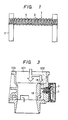
- FIG. 1 shows a structural view of an exothermic resistor being utilized in a hot wire air flow meter.
- An exothermic resistor 1 for detecting an amount of intake air flow has a platinum wire 2 in the form of a coil and has no bobbin therein.
- the coiled platinum wire 2 is in outer diameter about 20 ⁇ m and about 5 mm long. Both end sides of the coiled platinum wire 2 are welded to two supporting members 3, respectively.
- An outer surface of the coiled platinum wire 2 is overcoated almost in the cylindrical form with an inorganic glass material member 4 in the light of corrosion resistance and mechanical strength. Both end sides of the exothermic resistor 1 are not overcoated with the glass material member 4 and remains unovercoated and then are practiced under lap winding state in consideration of welding working with the supporting member 3.
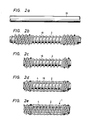
- Fig. 2a shows a structural view of a core wire 18.
- the core wire 18 is made of a molybdenum wire in the form of straight and having an outer diameter about 0.5 mm.
- the molybdenum core wire 18 is used as a core wire for winding the platinum wire 2 on an outer surface thereof.
- Fig. 2b shows a platinum wire 2 in combination with the core wire 18.
- the platinum wire 2 is wound continuously in plural pieces state with an outer surface of the molybdenum core wire 18 by means of a coil winding mechanism. At interval of about 5 mm, the platinum wire 2 is wound at close coiling state and also at lap winding state.
- Fig. 2c shows one piece of the coiled platinum wire 2 being wound around on an outer surface of the molybdenum core wire 18.
- the single coiled platinum wire 2 in combination with the molybdenum core wire 18 is made by cutting the center of the lap winding portion at both sides and made out about 5 mm length.
- Fig. 2d shows both the molybdenum core wire 18 and the coiled platinum wire 2 being overcoated and baked by the inorganic glass material member 4.
- the coiled platinum wire 2 is overcoated within the glass material member 4, except for both end sides thereof.
- Fig. 2e shows the exothermic resistor 1 free from a bobbin.
- the exothermic resistor 1 is made out removing the molybdenum core wire 18 from the compound structure body shown in Fig. 2d using a mixed acid composed of a nitric acid and a sulfuric acid. Thus, the exothermic resistor 1 has no bobbin therein.
- the exothermic resistor free from a bobbin 1 is welded with the supporting member 3 at both end sides thereof.
- the exothermic resistor 1 may be welded with lead wires and then the lead wires may be connected to the supporting member 3.
- the hot wire air flow meter having the above exothermic resistor 1 free from a bobbin is disposed within a bypass air passage of the internal combustion engine.
- the above exothermic resistor 1 free from a bobbin is used as an air flow velocity measuring element 1A and as an air temperature measuring element 1B with the same structure member.
- the air temperature measuring element 1B consitutes of one of the components in the hot wire air flow meter.
- the hot wire air flow meter having the air flow velocity measuring element 1A as a hot wire element and the air temperature measuring element 5 as a cold wire element is disposed in a bypass air passage 102 of the internal combustion engine.
- a body 103 of the internal combustion engine has a main air passage 101 and the bypass air passage 102 being branched from the main air passage 101. Most parts of the intake air passes through the main air passage 101 and the part of the intake air bypasses through the bypass air passage 102.
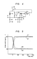
- the electric driving circuit is constitutes of the air flow velocity measuring element 1A, the air temperature measuring element 1B, operation amplifiers 6 and 7, a power transistor 8, a condensor 9, and resistances 10, 11, 12, 13 and 14.
- a collector terminal of the power transistor 8 connnects to a plus pole of a battery, and an earth terminal of the resistance 10 connects to a minus pole of the battery, respectively.
- a connection junction 17 between the resistance 10 and the air flow velocity measuring element 1A connects to an input terminal of a microprocessor.
- the microprocessor controls the internal combustion engine utilizing an output of the hot wire air flow meter.
- the power transistor 8 supplies an electric current to the air flow velocity measuring element 1A and thereby the air flow velocity measuring element 1A is heated.
- the temperature of the air flow velocity measuring element 1A is controlled at all times at a predetermined temperature, which is higher than that of the temperature of the air temperature measuring element 1B.
- the air temperature measuring element 1B is conducted only microcurrent, in which the quantity of the exothermic heat is neglegible small, and detects an intake air temperature.
- Such an air temperature measuring element 1B is used as an intake air temperature compensating member.
- a temperature difference between the air flow velocity measuring element 1A and the air temperature measuring element 1B is controlled at all times at a predetermined value by the operation of the electric driving circuit.
- the above operation in the electric driving circuit acts to give a feedback function so as to equalize at all times the voltage which is difference voltage between one end side of the air flow velocity measuring element 1A and another end side thereof devided by resistances 11 and 12, and other voltage which is voltage drop of the resistance 10 being amplified by the operation amplifier 7.
- the voltage drop of the resistance 10 is caused by the electric current flowing the air flow velocity measuring element 1A.
- the electric current flowing the air velocity measuring element 1A also varies. Therefore, the amount of the air flow can be measured according to the voltage drop of the resistance 10 in response to the varied electric current.
- the quantity of heat generated on the coiled platinum wire 2 of the air flow velocity measuring element 1A and the air temperature measuring element 1B hardly transmit through the supporting members 3 or lead wires, and is carried away almost through air.
- the response characteristics of the hot wire air flow meter free from a bobbin of the embodiment of the present invention is illustrated in Fig. 5.
- the ouput voltage of the hot wire air flow meter converts into the flow amount under the condition the amount of air flow changed over.
- curve A1 shows the hot wire air flow meter free from a bobbin of the present invention
- curve B1 shows the hot wire air flow meter having a bobbin, when the amount of air flow is changed over from low flow amount (about 20kg/h) to high flow amount (about 200kg/h).
- Curve A2 shows the hot wire air flow meter free from a bobbin of the present invention
- curve B2 shows the hot wire air flow meter having a bobbin, when the amount of air flow is changed over from high flow amount (about 200kg/h) to low flow amount (about 20kg/h).
- the hot wire air flow meter free from a bobbin of the present invention can be improved carry-over time for final value in comparison with the hot wire air flow meter having a bobbin as the prior art.
- the hot wire air flow meter free from a bobbin of the present invention can make an output signal comply with real change of the amount of air flow. Therefore, suitable injection amount of the injector can be determined and the problem of the surging phenomenon can be dissolved.
- the productivity of the exothermic resistor can be improved and the exothermic resistor can be provided at low price.
- the hot wire air flow meter of the present invention can be attained an excellent corrosion resistance. So both end sides of the coiled platinum wire are wound at lap winding, the hot wire air flow meter free from a bobbin of the present invention can be improved an excellent mechanical strength.
- the platinum wire is explained as one of the metal wire, however a tungustin wire can be applied and it can be expected to show same effects as described in the platinum wire.
Landscapes
- Physics & Mathematics (AREA)
- General Physics & Mathematics (AREA)
- Fluid Mechanics (AREA)
- Engineering & Computer Science (AREA)
- Microelectronics & Electronic Packaging (AREA)
- Aviation & Aerospace Engineering (AREA)
- Ceramic Engineering (AREA)
- Electromagnetism (AREA)
- Measuring Volume Flow (AREA)
Applications Claiming Priority (2)
| Application Number | Priority Date | Filing Date | Title |
|---|---|---|---|
| JP223580/85 | 1985-10-09 | ||
| JP60223580A JPH0680408B2 (ja) | 1985-10-09 | 1985-10-09 | 感熱式空気流量計及び感熱抵抗体 |
Publications (2)
| Publication Number | Publication Date |
|---|---|
| EP0218232A1 true EP0218232A1 (fr) | 1987-04-15 |
| EP0218232B1 EP0218232B1 (fr) | 1990-01-31 |
Family
ID=16800392
Family Applications (1)
| Application Number | Title | Priority Date | Filing Date |
|---|---|---|---|
| EP86113872A Expired - Lifetime EP0218232B1 (fr) | 1985-10-09 | 1986-10-07 | Débitmètre à fil chaud pour l'air |
Country Status (7)
| Country | Link |
|---|---|
| US (1) | US4790182A (fr) |
| EP (1) | EP0218232B1 (fr) |
| JP (1) | JPH0680408B2 (fr) |
| KR (1) | KR910000360B1 (fr) |
| CN (1) | CN1012754B (fr) |
| CA (1) | CA1291883C (fr) |
| DE (1) | DE3668695D1 (fr) |
Cited By (5)
| Publication number | Priority date | Publication date | Assignee | Title |
|---|---|---|---|---|
| GB2204696A (en) * | 1987-05-12 | 1988-11-16 | Smith Ind Plc | Temperature sensor |
| DE3823620A1 (de) * | 1987-07-13 | 1989-01-26 | Hitachi Ltd | Hitzdraht-luftdurchflussmengenmesser |
| DE3833289A1 (de) * | 1987-09-30 | 1989-04-20 | Hitachi Ltd | Hitzdraht-luftdurchflussmesser, verfahren zu seiner herstellung und seine verwendung |
| DE4004552A1 (de) * | 1989-02-14 | 1990-08-16 | Mitsubishi Electric Corp | Signalverarbeitungsverfahren fuer einen durchflusssensor vom thermischen typ |
| EP0323005A3 (fr) * | 1987-09-30 | 1991-11-21 | Hitachi, Ltd. | Débitmètre d'air du type fil chaud |
Families Citing this family (15)
| Publication number | Priority date | Publication date | Assignee | Title |
|---|---|---|---|---|
| JP2790824B2 (ja) * | 1988-10-25 | 1998-08-27 | 株式会社日立製作所 | 熱式空気流量計の発熱抵抗体保護方法とその発熱抵抗体 |
| US5181008A (en) * | 1990-10-15 | 1993-01-19 | Martin Kevin B | Diamond encapsulated resistance temperature detector |
| JP2846518B2 (ja) * | 1992-03-18 | 1999-01-13 | 株式会社日立製作所 | 空気流量検出器及びそれを使用したエンジン制御装置 |
| US5544079A (en) * | 1994-07-15 | 1996-08-06 | Hitachi America, Ltd. | Smart mass gas flow sensor |
| US6062077A (en) * | 1997-10-17 | 2000-05-16 | Azima; Faramarz | Techniques for making and using a sensing assembly for a mass flow controller |
| US10539366B2 (en) | 2014-04-30 | 2020-01-21 | Stephen B. Maguire | Method and apparatus for vacuum drying granular resin material |
| DE102005001809A1 (de) * | 2005-01-13 | 2006-07-27 | Endress + Hauser Flowtec Ag | Verfahren zur Regelung eines thermischen bzw. kalorimetrischen Durchflussmessgeräts |
| JP4805091B2 (ja) * | 2006-10-24 | 2011-11-02 | 株式会社堀場エステック | 熱式質量流量センサ及びマスフローコントローラ |
| US8141270B2 (en) * | 2009-08-13 | 2012-03-27 | Maguire Products, Inc. | Gas flow rate determination method and apparatus and granular material dryer and method for control thereof |
| WO2018047385A1 (fr) * | 2016-09-08 | 2018-03-15 | 株式会社村田製作所 | Dispositif de mesure de vitesse de vent et dispositif de mesure de volume de vent |
| IT201700112681A1 (it) * | 2017-10-06 | 2019-04-06 | Eltek Spa | Dispositivo di controllo idraulico per apparecchi e sistemi a conduzione di liquido |
| US20190308344A1 (en) | 2018-04-04 | 2019-10-10 | Novatec, Inc. | Method and apparatus for polymer drying using inert gas |
| US11364657B2 (en) | 2018-04-04 | 2022-06-21 | Novatec, Inc. | Reducing moisture in granular resin material using inert gas |
| CN111765935A (zh) * | 2020-08-17 | 2020-10-13 | 山东普为电子科技有限公司 | 小型热式气体质量流量计 |
| CN113390604B (zh) * | 2021-07-16 | 2023-03-03 | 中国空气动力研究与发展中心设备设计与测试技术研究所 | 一种适用于高速流场测量的一维热线探头 |
Citations (4)
| Publication number | Priority date | Publication date | Assignee | Title |
|---|---|---|---|---|
| US4228683A (en) * | 1975-06-19 | 1980-10-21 | Bayer Aktiengesellschaft | Method of determining liquid flow in a conduit |
| EP0116144A1 (fr) * | 1982-12-08 | 1984-08-22 | Hitachi, Ltd. | Débimètre thermique pour l'air |
| EP0118117A1 (fr) * | 1983-03-07 | 1984-09-12 | Hitachi, Ltd. | Débitmètre thermique pour l'air |
| DE3431952A1 (de) * | 1983-09-02 | 1985-03-21 | Nippondenso Co., Ltd., Kariya, Aichi | Vorrichtung zum messen eines gasstromes |
Family Cites Families (13)
| Publication number | Priority date | Publication date | Assignee | Title |
|---|---|---|---|---|
| US971101A (en) * | 1908-07-23 | 1910-09-27 | Gen Electric | Electric heating unit. |
| US2269850A (en) * | 1939-11-21 | 1942-01-13 | William O Hebler | Gas analysis apparatus |
| US2287460A (en) * | 1940-11-29 | 1942-06-23 | Rca Corp | Insulated heater and method of manufacture |
| US2319516A (en) * | 1941-11-28 | 1943-05-18 | Weaver Mfg Co | Gas flow indicator |
| US2624199A (en) * | 1946-03-29 | 1953-01-06 | Myron H Boyer | Fluid flowmeter |
| US3246515A (en) * | 1963-02-28 | 1966-04-19 | Dynamics Corp America | Thermal responsive fluid flow measuring probe |
| DE1523270C3 (de) * | 1966-04-16 | 1974-02-21 | Vierling, Oskar, Prof. Dr., 8553 Ebermannstadt | Anordnung zum Messen der Geschwindigkeit und Richtung eines Gasstromes mit optischer und akustischer Anzeige des Meßergebnisses, insbesondere zum Ermitteln der Vertikalgeschwindigkeit von Luftfahrzeugen |
| DE2151774C3 (de) * | 1971-10-18 | 1980-04-03 | Robert Bosch Gmbh, 7000 Stuttgart | Kraftstoffeinspritzanlage für eine Brennkraftmaschine |
| JPS56108907A (en) * | 1980-01-31 | 1981-08-28 | Hitachi Ltd | Detector for sucked air flow rate of internal combustion engine |
| JPS5722563A (en) * | 1980-07-15 | 1982-02-05 | Hitachi Ltd | Sucked air flowmeter for internal combustion engine |
| JPS5931412A (ja) * | 1982-08-16 | 1984-02-20 | Hitachi Ltd | 熱線式空気流量計 |
| JPS6060521A (ja) * | 1983-09-14 | 1985-04-08 | Hitachi Ltd | 内燃機関の吸入空気流量測定装置 |
| FR2746456B1 (fr) * | 1996-03-21 | 1998-04-30 | Snecma | Dispositif de retenue du pied des aubes d'une soufflante |
-
1985
- 1985-10-09 JP JP60223580A patent/JPH0680408B2/ja not_active Expired - Lifetime
-
1986
- 1986-09-30 US US06/913,379 patent/US4790182A/en not_active Expired - Lifetime
- 1986-10-06 KR KR1019860008344A patent/KR910000360B1/ko not_active Expired
- 1986-10-07 DE DE8686113872T patent/DE3668695D1/de not_active Expired - Lifetime
- 1986-10-07 EP EP86113872A patent/EP0218232B1/fr not_active Expired - Lifetime
- 1986-10-08 CN CN86107072A patent/CN1012754B/zh not_active Expired
- 1986-10-08 CA CA000520139A patent/CA1291883C/fr not_active Expired - Lifetime
Patent Citations (4)
| Publication number | Priority date | Publication date | Assignee | Title |
|---|---|---|---|---|
| US4228683A (en) * | 1975-06-19 | 1980-10-21 | Bayer Aktiengesellschaft | Method of determining liquid flow in a conduit |
| EP0116144A1 (fr) * | 1982-12-08 | 1984-08-22 | Hitachi, Ltd. | Débimètre thermique pour l'air |
| EP0118117A1 (fr) * | 1983-03-07 | 1984-09-12 | Hitachi, Ltd. | Débitmètre thermique pour l'air |
| DE3431952A1 (de) * | 1983-09-02 | 1985-03-21 | Nippondenso Co., Ltd., Kariya, Aichi | Vorrichtung zum messen eines gasstromes |
Cited By (6)
| Publication number | Priority date | Publication date | Assignee | Title |
|---|---|---|---|---|
| GB2204696A (en) * | 1987-05-12 | 1988-11-16 | Smith Ind Plc | Temperature sensor |
| DE3823620A1 (de) * | 1987-07-13 | 1989-01-26 | Hitachi Ltd | Hitzdraht-luftdurchflussmengenmesser |
| DE3823620C2 (fr) * | 1987-07-13 | 1992-03-05 | Hitachi, Ltd., Tokio/Tokyo, Jp | |
| DE3833289A1 (de) * | 1987-09-30 | 1989-04-20 | Hitachi Ltd | Hitzdraht-luftdurchflussmesser, verfahren zu seiner herstellung und seine verwendung |
| EP0323005A3 (fr) * | 1987-09-30 | 1991-11-21 | Hitachi, Ltd. | Débitmètre d'air du type fil chaud |
| DE4004552A1 (de) * | 1989-02-14 | 1990-08-16 | Mitsubishi Electric Corp | Signalverarbeitungsverfahren fuer einen durchflusssensor vom thermischen typ |
Also Published As
| Publication number | Publication date |
|---|---|
| KR870004309A (ko) | 1987-05-08 |
| JPS6283622A (ja) | 1987-04-17 |
| CN1012754B (zh) | 1991-06-05 |
| JPH0680408B2 (ja) | 1994-10-12 |
| US4790182A (en) | 1988-12-13 |
| DE3668695D1 (de) | 1990-03-08 |
| EP0218232B1 (fr) | 1990-01-31 |
| KR910000360B1 (ko) | 1991-01-24 |
| CA1291883C (fr) | 1991-11-12 |
| CN86107072A (zh) | 1987-04-29 |
Similar Documents
| Publication | Publication Date | Title |
|---|---|---|
| EP0218232B1 (fr) | Débitmètre à fil chaud pour l'air | |
| US4517837A (en) | Air flow rate measuring apparatus | |
| US4513615A (en) | Thermal air flow meter | |
| EP0380581B1 (fr) | Detecteur de courants fluides | |
| US4344322A (en) | Device for air flow rate measurement in the air intake tube of an internal combustion engine | |
| EP0118117A1 (fr) | Débitmètre thermique pour l'air | |
| US4357830A (en) | Gas flow measuring apparatus | |
| US5367906A (en) | Hot wire air flow meter | |
| GB2039051A (en) | Device for measuring a flowing medium | |
| US4369656A (en) | Air intake measuring device for internal combustion engine | |
| US4299125A (en) | Air quantity metering apparatus | |
| US5423210A (en) | Air flow rate meter and air flow rate detection | |
| US4793176A (en) | Hot film type air flow meter having a temperature sensing exothermic resistor | |
| JPH0682056B2 (ja) | 流量計用抵抗素子 | |
| US4672847A (en) | Hot-wire flow rate measuring apparatus | |
| US4450714A (en) | Apparatus for measuring the mass of a flowing medium | |
| US4471655A (en) | Gas flow rate measuring apparatus | |
| GB2196433A (en) | Hot wire air flow meter | |
| US4414847A (en) | Gas flow measuring apparatus | |
| US4538457A (en) | Apparatus for measuring the mass of a flowing medium | |
| US4261199A (en) | Air flow measurement apparatus | |
| EP0581896A1 (fr) | Detecteur thermique de flux massique | |
| JPS59190623A (ja) | 熱式空気流量計 | |
| JPH0814977A (ja) | 熱式流量計 | |
| JP2530988B2 (ja) | 熱式流量計 |
Legal Events
| Date | Code | Title | Description |
|---|---|---|---|
| PUAI | Public reference made under article 153(3) epc to a published international application that has entered the european phase |
Free format text: ORIGINAL CODE: 0009012 |
|
| AK | Designated contracting states |
Kind code of ref document: A1 Designated state(s): DE FR GB |
|
| 17P | Request for examination filed |
Effective date: 19870423 |
|
| 17Q | First examination report despatched |
Effective date: 19880929 |
|
| GRAA | (expected) grant |
Free format text: ORIGINAL CODE: 0009210 |
|
| AK | Designated contracting states |
Kind code of ref document: B1 Designated state(s): DE FR GB |
|
| REF | Corresponds to: |
Ref document number: 3668695 Country of ref document: DE Date of ref document: 19900308 |
|
| ET | Fr: translation filed | ||
| PLBE | No opposition filed within time limit |
Free format text: ORIGINAL CODE: 0009261 |
|
| STAA | Information on the status of an ep patent application or granted ep patent |
Free format text: STATUS: NO OPPOSITION FILED WITHIN TIME LIMIT |
|
| 26N | No opposition filed | ||
| PGFP | Annual fee paid to national office [announced via postgrant information from national office to epo] |
Ref country code: FR Payment date: 19910816 Year of fee payment: 6 |
|
| PG25 | Lapsed in a contracting state [announced via postgrant information from national office to epo] |
Ref country code: FR Effective date: 19930630 |
|
| REG | Reference to a national code |
Ref country code: FR Ref legal event code: ST |
|
| PGFP | Annual fee paid to national office [announced via postgrant information from national office to epo] |
Ref country code: GB Payment date: 20000921 Year of fee payment: 15 |
|
| PGFP | Annual fee paid to national office [announced via postgrant information from national office to epo] |
Ref country code: DE Payment date: 20001229 Year of fee payment: 15 |
|
| PG25 | Lapsed in a contracting state [announced via postgrant information from national office to epo] |
Ref country code: GB Free format text: LAPSE BECAUSE OF NON-PAYMENT OF DUE FEES Effective date: 20011007 |
|
| REG | Reference to a national code |
Ref country code: GB Ref legal event code: IF02 |
|
| GBPC | Gb: european patent ceased through non-payment of renewal fee |
Effective date: 20011007 |
|
| PG25 | Lapsed in a contracting state [announced via postgrant information from national office to epo] |
Ref country code: DE Free format text: LAPSE BECAUSE OF NON-PAYMENT OF DUE FEES Effective date: 20020702 |