EP0218258A2 - System und Verfahren zur Programmstrukturierung durch Datentabellenübersetzung - Google Patents
System und Verfahren zur Programmstrukturierung durch Datentabellenübersetzung Download PDFInfo
- Publication number
- EP0218258A2 EP0218258A2 EP86114037A EP86114037A EP0218258A2 EP 0218258 A2 EP0218258 A2 EP 0218258A2 EP 86114037 A EP86114037 A EP 86114037A EP 86114037 A EP86114037 A EP 86114037A EP 0218258 A2 EP0218258 A2 EP 0218258A2
- Authority
- EP
- European Patent Office
- Prior art keywords
- item
- software
- data
- relation
- relations
- Prior art date
- Legal status (The legal status is an assumption and is not a legal conclusion. Google has not performed a legal analysis and makes no representation as to the accuracy of the status listed.)
- Granted
Links
Images





Classifications
-
- G—PHYSICS
- G06—COMPUTING OR CALCULATING; COUNTING
- G06F—ELECTRIC DIGITAL DATA PROCESSING
- G06F8/00—Arrangements for software engineering
- G06F8/20—Software design
Definitions
- the present invention generally relates to software structuring system and method which can be adopted in a system for designing and developing softwares (programs).
- the invention is concerned with a table-translation type software structuring system and method suited for designing and developing software which is functionally adapted to handle input/output data in the form of table-formated data.
- An object of the present inventin is to overcome the problems of the prior art described above and provide a software structuring system and method of table translation type which allows the data structure and the processing procedure to be integrally designed, while admitting the reuse of the intermediate results obtained in the course of design as well as the trial-and-error procedure.
- table-formated data are inputted from a data file such as a disk, magnetic tape or the like, simple calculation is performed and the results thereof are outputted also in the table-formated data. Accordingly, if it is possible to utilize the data format (table) in the data processing itself, the intermediate results obtained only internally can then be imparted with meaning by making use of the data concerning the table format.
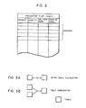
- the table-formated data will be referred to simply as the table. With the term "table”, it is thus intended to mean a collection of records of sets of attributes representing natures of individual data. Thus, the table can be expressed two-dimensionally with the fields containing the attributes and the records, as shown in Fig. 2 of the accompanying drawings.
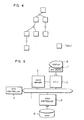
- the software assumes a tree-like form.
- the tree trunk receives as the input data the tables corresponding to the leaves with the top table representing the output data, while branches represent softwares to be processed (or to undergo table translation procedure).
- An intermediate table constituting the tree trunk represents the subordinative processing and can be handled as a component part, so to speak, for performing the subordinate processing.
- Fig. 5 is a view showing schematically in a block diagram a general arrangement of a hardware structure of a computer operative with a production management software developing system to which the table-translation software structuring method according to the present invention can be applied.
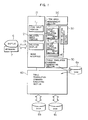
- Fig. 1 is a view for illustrating a software structure of the production management software developing system which can run on the computer system shown in Fig. 5. In this connection, it should be noted that the system shown in Fig. 1 may also be realized in a hardware structure.
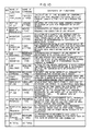
- Fig. 6 is a view for illustrating the forms describing the table translation commands created by the production management software developing system according to the illustrated embodiment of the invention.
- Fig. 1 is a view for illustrating illustrating describing the table translation commands created by the production management software developing system according to the illustrated embodiment of the invention.
- FIG. 7 is a view for illustrating a table translation process adapted to be executed by the production management software designed and developed by the software structuring method according to the inventin in conjunction with a part explosion procedure, by way of example.
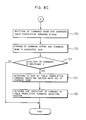
- Figs. 8A to 8C are views for illustrating in a flow chart processing executed by the production management software developing system.
- the computer for the production management software developing system is composed of a multi-bus 1, a bus controller 2 for controlling the multibus 1, a central processing unit or CPU 3 connected to the multi-bus 1, a disk controller 4, a main storage or memory 5, a display 6, a keyboard 7 and a disk 8 connected to the disk controller 4, wherein the main memory 5, the display 6 and the keyboard 7 are connected to the CPU 3.
- Data inputted through the keyboard 7 are fetched by the CPU 3 to be stored in the main memory 5 and displayed on the display unit 6.
- the data placed in the main memory 5 is sent to the disk controller 4 through the multi-bus 1 under the control of the CPU 3 and subsequently stored in the disk 8 from the disk controller 4.
- the production management software developing system under consideration includes in addition to the display unit 6, the keyboard 7 and the disks 8a, 8b and 8c (generally denoted by 8 in Fig. 5) mentioned above, an image interface 10, an item area management section 20, item/relation management section 30, a table relation management section 40, a table-translation command string creating section 50, and a table-translation executing section 60.
- the image interface 10 includes an item input portion 11, a relation input portion 12 and a relation indicating portion 13, while the table relation management section 40 is constituted by an intra-table relation management portion 41 and an intra-table relation management portion 42.
- the table translation command string generating section 50 serves to convert or translate a table translation process designed by the production management software developing system into a table translation command string which may comply with the description format illustrated in Fig. 6, by way of example.
- the table translation command string is then stored in the disk 8a.
- the table translation commands illustrated in Fig. 6 are expressed in a computer language developed by the assignee of the present application, and bear similarity to the description format of the relational type data base language. More specifically, this language has a strubture based on the relational type data base language SQL (an abbreviation of Structure Query Language) recommended by the International Organization for Standardization (ISO).
- SQL an abbreviation of Structure Query Language
- the commands allowed to be described in a definition area are the basic commands illustrated in Fig. 9.
- the production management functions are described in terms of these commands in this language.
- the purpose, contents and the intended applications of this language are mentioned below.
- this language is to enhance the productivity of the production management software and make possible the stepwise extension of the production management software.
- this language is structured on the basis of the relational type data base and suited for the production or factory management, regardless of the type of data.
- the language is composed of two types of command groups mentioned below so as to be easily understood by those in charge of production management who are not always required to have adequate knowledge about the computer technology.
- This language is intended for the processing of data in the form of table which forms a major proportion of the various production management softwares.
- the matter in concern is primarily such kind of data processing in which tables on file are inputted for executing relatively simple calculations, the results of which is returned to the file in the form of output tables.
- This language is capable of flexibly describing softwares which are subjected to the phased increase in their scales and to the phased modification.
- the language in concern has been developed starting from the standpoint that the data processing through the production management software may be regarded as a process for translating an input table to an output table and is characterized by the capability of easily describing the table translation. Further, this language is intended to be applied to such data processing in which table in files occupying a major part of the production management software are inputted for performing relatively simple calculations and the output tables containing the results of the calculation are returned to the associated files.
- This language can be easily understood as compared with the conventional languages (COBOL, FORTRAN) and the number of steps for creating a production management software can be decreased by a factor of 1/15.
- production management command MIMS is commercially available from GE Co.
- MIMS is however limited to particular applications and lacks flexibility (e.g. the contents of commands can not be altered or modified). Further, a relational type data base retrieving language bearing a similarity to the table translation function is known. However, MIMS can not be used for describing the logics involved in the production or factory management.
- the table translation executing section 60 fetches therein the table translation commands stored in the disk 8a and executes sequentially the table translation commands.
- Fig. 11 shows a structure of a program executed by the table translation executing section 60 by using the language described above.
- macrocommand and basic commands as inputted are once placed in an input spooler 71, wherein the commands on the spooler are sequentially executed through command analyzing procedure.
- Functions of the various blocks shown in Fig. 11 are summarized below:
- part explosion it is intended to mean the fucntion for arithmetically determining or calculating the quantity or number of component parts and a period (time span) required for manufacturing a designated quantity (or number) of products till an appointed date of delivery in accordance with a scheduled production plan.
- the function of part explosion may be expressed in terms of a process of table translation as illustrated in Fig. 7.
- a production plan table containing items concerning the product, quantity, the date of delivery and the production starting date is inputted together with a standard schedule table listing the product and the number of days required for the production to determine the start date which has been pending until then, and a producton plan table is outputted.
- the production plan table is inputted together with a part arrangement table listing the items concerning the product, part and the number of parts whereby a part request table listing items concerning the product, quantity and the appointed date of delivery is outputted.
- the production management software developing system is so arranged as to design and develop the production management software in terms of a process of table translations. More specifically, with the aid of the production management software developing system, an engineer in charge of designing a production management software may execute the table translation process in the manner described below.
- a command requesting the indication or display of the item area difined at the instant time point is inputted by manipulating the keyboard shown in Figs. 1 and 5.
- the inputted command is displayed on the display 6 under the control of the CPU 3, and at the same time sent to the image interface 10 shown in Fig. 1.
- the image interface 10 reads out the item area defined already from the item area management section 20 to display the area on the display unit 6. It is assumed that at this time point, no definition has been made yet.
- the software engineer inputs from the keyboard the data concerning the product, the number of days taken for production, quantity, the date of delivery, component parts and the number thereof which are required for loading the production plan table, the standard schedule table and the part arrangement table which are necessary for defining the table translation process representative of the part explosion (step 100 in Fig. 8A).
- the input items are registered in the item area management section 20 as an item definition area by way of the item input portion 11 incorporated in the image interface 10 (step 102).
- step 103 inter-item dependence relation providing fundamental information for preparing the input table is inputted (a step 104).
- the software engineer operates the keyboard 7 to input the information representative of the presence of a dependence relation between the product and the number of days required for the production thereof.
- This relation is expressed by "Product ⁇ the Number of Days".
- the presence of the dependence relation between "Product” and "The Number of Days” means that when a product (code) is determined, the number of days for realizing that product can be determined definitely.
- the table listing the product and the number of days for realizing the product can be prepared with the product code being used as a key code.
- the inter-item relationship "Product ⁇ The number of Days" inputted from the keyboard 7 is registered in the item relation management section 30 through the relation input portion 12 incorporated in the image interface 10 (step 106).
- the interitem relations conceived by the designer i.e. "Product ⁇ Quantity", “Product ⁇ Date of Delivery”, “Product ⁇ Start Date” and "Product/Parts ⁇ Number of Parts” can be registered in the item relation management section 30 (step 104).
- the software developing system checks whether the items participating in the relation being inputted, e.g. the items "Product” and "Quantity", are already defined in the item area management section 20. If the items are not yet defined, information of input error or necessity of additional definition is displayed on the display unit 6 to prompt the designer to make decision or other appropriate processing. Further, every time the relation is inputted, the system checks as to the possibility of contradiction. If contradiction is detected, the system prompts the operator to repeat the inputting operation.
- the software designer inputs the items of the production plan table which constitutes an output table and the inter-item relations (step 108 in Fig. 8A). More specifically, the designer operates the keyboard 7 to input the items concerning the product, quantity, date of delivery and the production starting date.
- the image interface 10 checks as to whether every input item has been already registered in the item area management section (step 109) and fetched all the dependence relations relevant to the item from the item/relation management section 30 to display them on the display unit 6.
- the designer inputs the derivation relations between the items (i.e. the sequential relationship in which the items are arithmetically processed from the keyboard 7 (step 114).
- the inputted inter-item derivation relation is transferred to the table relation management section 40 to be registered in the intra-table relation management section 41 through the image interface 10 (step 116).
- consideration is given to the item of the production starting data.
- the image interface 10 confirms that data has been defined in the item area management section 20 (i.e. the designer has already inputted that item as the item area definition) and displays the dependence relation "Product - Start Date" on the display unit 6.
- the name of the output table is inputted (step 118).
- the image interface 10 fetches from the item relation management section 30 the dependence relations concerning the product, quantity, delivery date and the start date while fetching the derivation relations from the intra-table relation management section 41 for determing the input table on the basis of the inter-item relations contained in the output table.
- the image interface displays combinations for the input table which can be adopted (step 120). For example, the display 6 may display the following combinations:
- the deisgner can operate the keyboard 7 to input a command for generating the command string for the part explosion.
- the command for generating the command string is sent to the table translation command generating section 50 through the image interface 10.
- the table translation command string generating section 10 fetches information concerning the table translation process for the part explosion from the intra-table relation management section 41 and the inter-table relation management section 42, to create the command string for the part explosion (step 128).
- description will be made on the creation or generation of the table translation command string in conjunction with the part explosion, by way of example.
- the table translation command string generating section 50 serves to transform the software designed already into the format capable of being executed by the executing section described hereinbefore. More specific strictlyally, the table translation command string generating section 50 fetches the name of the input table, the items contained therein and the required inter-table relation from the inter-table relation management section 42, while fetching the derivation relation of the items contained in the output table from the intra-table relation management section 41, to generate the table translation command string in accordance with the format of description of command shown in Fig. 6. As mentioned hereinbefore, with the phrase "part explosion function", it is intended to mean the function of calculating the quantity of parts and the time required for manufacturing a designated number of ordered products till the date of delivery in accordance with the scheduled production plan.
- EXPLODE This function may also be referred to as the explosion of required quantity.
- EXPLODE the function of part explosion
- the result of calculation is placed in the column labelled "Start Date" of the production plan table.
- the required part table containing the items "Part”, “Quantity” and “Delivery Date” is prepared.
- the part explosion function resides in preparation of the part request table on the basis of the production plan table, the standard schedule table and the part arrangement table.
- the part explosion can be expressed in terms of a tree-like software architecture, as will be seen in Fig. 12, and provides the design information described hereinbefore and illustrated in Figs. 13A to 13F.
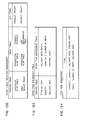
- Figs. 13A to 13F are views illustrating the management functions carried out by the various management sections 20, 30, 40 - 42 and 50 shown in Fig. 1. More specifically, Fig. 13A shows the table management for managing all the tables used by the system. Fig. 13B illustrates the item management for managing attributes and lengths of all the items used in the system. Fig. 13C illustrates the intra-table relation management for managing the item constituting the table used by the system. Fig. 13D shows the inter-table relation management for managing the derivation relations among the tables used by the system. Fig. 13E shows the inter-item relation management for managing the derivation relations among the items.Fig. 13 shows the item area management.
- the production starting date is determined from the standard schedule table and the production plan table, whereby the production plan table containing the item "Start Date" is prepared.
- the intra-table relation management section has registered therein as the items the standard schedule table and the production plan table, as shown in Fig. 13C. From the inter-table relation management shown in Fig. 13D, it can be seen that the production plan table mentioned above is prepared from the subordinative production plan table and the standard schedule table. Further, it is shown that the key item used is "Product”. From the inter-item relation management shown in Fig. 13E, it can be seen that the date of starting the production is determined in accordance with (Delivery Date - Number of Days + 1). The intra-table relation management shown in Fig.
- FIG. 13C holds information concerning the tables to which the individual items should belong. Further, the item management shown in Fig. 13B contains information concerning the attributes and the lengths of the various items. In this conjunction, it will be noted that the attributes and lengths of data provide important factors in development of software.
- the command string generating section creates or generates the command for the part explosion (EXPLODE).
- the processing at the level 1 outputs the production plan table which also serves as the input table, as will be seen from the table management shown in Fig. 13A.
- a command "UPDATE” is generated.
- the production plan table is extracted from the column “Derived Table” of the intertable relation management shown in Fig. 13D and decision is made to the effect that the input tables for the preparation of this production plan table are the subordinative production plan table and the standard schedule table and that the key item is "Product”.
- the inter-item relation management shown in Fig. 13E it is decided that determination of the production starting date requires calculation according to (Delivery Date - Number of Days + 1).
- EXPLODE UPDATE Production Plan Table
- KEY "Product” UPDATE Standard Schedule Table
- KEY "Product”
- SET Date of Start Delivery Date - Number of Days + 1 ... (1)
- INSERT INTO Part Request Table Product, Quantity, Delivery Date
- KEY "Product” Part Arrangement Table
- KEY “Product”...
- a string of table translation commands are created, as described above. Subsequently, the names of created commands are inputted (step 130).
- the string of the created table translation commands is stored in the disk 8a (step 132).
- instruction for executing that command is inputted from the keyboard 7.
- the table translation command executing section 60 is activated to fetch the desired command from the disk 8a (step 134) to allow the command to be executed (step 136).
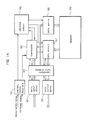
- Fig. 14 shows in a block diagram a circuit arrangement of the intra-table relation management section 41 assumed to be implemented in hardware. It should be understood that the item area management section 20, the item relation management section 30 or the inter-table relation management section 40 can also be realized in a similar circuit configuration.
- a control signal receiver 91 receives a registration signal, and a data input circuit 92 receives data to be registered.
- the input data includes the table name (i.e. Production Plan Table) and the column name (i.e. Product, Quantity, Delivery Date and Production Start Date) and is given in the form of a character string obtained by coding "Production Plan Table (Product, Quantity, Delivery Date, Production Start Date)".
- the data received by the data input circuit is transferred to a temporary data storage 94.
- a comparator 96 operates to compare the input data (i.e.
- the data on the memory 99 is fetched by a data reader 97 in dependence on the output signal from the comparator 95 to be subsequently transferred to the temporary storage 94. Every time the data is fetched from the memory 99, a confirmation signal confirming the data fetch is supplied to the comparator 95 and the temporary data storage 94 from the data reader 97. The result of comparison performed by the comparator 95 is supplied to a decision circuit 96 in the form of ON or OFF signal.
- the decision circuit 96 receives the registration signal from the control signal receiver 91 to decide the location where the input data is to be registered in dependence on the combination of the signal output from the comparator 95 and the registration signal.
- the decision circuit 96 outputs a signal representative of the result of the decision, which signal is supplied to the comparator 95 and a data writer 98.
- the comparator 95 responds thereto to stop operation, while the data writer 95 receives data from the temporary data storage 94 and writes the data in the memory 99.
- the control signal receiver 91 receives a fetching signal, while the data input circuit 92 receives the data signal indicative of the table name.
- the data received by the input circuit 92 is transferred to the temporary data storage 94.
- the control signal receiver 91 outputs a signal indicating the fetching of data, which signal is supplied to the comparator 95 and the decision circuit 96.
- the comparator 95 supplies a signal to the data reader for reading out the data from the memory 99, the data read out being stored in the temporary data storage 94.
- This data is compared with the input data.
- the result of the comparison is supplied to the decision circuit 96 which in turn outputs a signal representative of the result of decision made with reference to predetermined criteria, the output signal being sent to the data reader 97.
- the latter reads out data from the memory 99 and sends the data to the temporary data storage 94, which data is then supplied to a data output circuit 93 to be outputted externally.
- a producton management software can be designed with an improved efficiency because the data structurization can be accomplished in parallel or simultaneously with the processing of data according to the present invention. Further, since the table translation commands can be created in the course of executing the table translation, improved correspondence can be realized between the design concept and the developed software.
Landscapes
- Engineering & Computer Science (AREA)
- Software Systems (AREA)
- General Engineering & Computer Science (AREA)
- Theoretical Computer Science (AREA)
- Physics & Mathematics (AREA)
- General Physics & Mathematics (AREA)
- Management, Administration, Business Operations System, And Electronic Commerce (AREA)
Applications Claiming Priority (2)
| Application Number | Priority Date | Filing Date | Title |
|---|---|---|---|
| JP60224705A JP2607467B2 (ja) | 1985-10-11 | 1985-10-11 | 表変換型ソフトウエア構成方式 |
| JP224705/85 | 1985-10-11 |
Publications (3)
| Publication Number | Publication Date |
|---|---|
| EP0218258A2 true EP0218258A2 (de) | 1987-04-15 |
| EP0218258A3 EP0218258A3 (de) | 1991-05-02 |
| EP0218258B1 EP0218258B1 (de) | 1994-01-05 |
Family
ID=16817952
Family Applications (1)
| Application Number | Title | Priority Date | Filing Date |
|---|---|---|---|
| EP19860114037 Expired - Lifetime EP0218258B1 (de) | 1985-10-11 | 1986-10-10 | System und Verfahren zur Programmstrukturierung durch Datentabellenübersetzung |
Country Status (3)
| Country | Link |
|---|---|
| EP (1) | EP0218258B1 (de) |
| JP (1) | JP2607467B2 (de) |
| DE (1) | DE3689502T2 (de) |
Cited By (3)
| Publication number | Priority date | Publication date | Assignee | Title |
|---|---|---|---|---|
| GB2195479A (en) * | 1986-09-05 | 1988-04-07 | Hitachi Ltd | Planning support method and system |
| EP0344497A3 (de) * | 1988-05-13 | 1992-04-08 | Hitachi, Ltd. | Verfahren und System zur Unterstützung von Entwurfsverfahren |
| EP0538883A3 (en) * | 1991-10-23 | 1993-10-27 | T A S & Trading Co Ltd | Method for creating accounting programs and processing accounting data |
Families Citing this family (6)
| Publication number | Priority date | Publication date | Assignee | Title |
|---|---|---|---|---|
| JP2585311B2 (ja) * | 1987-11-06 | 1997-02-26 | 株式会社日立製作所 | プログラム作成方法 |
| JPH02122339A (ja) * | 1988-11-01 | 1990-05-10 | Matsushita Electric Ind Co Ltd | ファイルアクセス手続き自動生成装置とその方法 |
| JP2525936B2 (ja) * | 1990-06-22 | 1996-08-21 | 株式会社日立情報システムズ | 事務処理方法 |
| US5761508A (en) * | 1992-01-31 | 1998-06-02 | Asahi Kasei Kogyo Kabushiki Kaisha | Information processing system and method applied to the development of computer programs |
| WO1993015458A1 (fr) * | 1992-01-31 | 1993-08-05 | Asahi Kasei Kogyo Kabushiki Kaisha | Appareil et procede de traitement des informations |
| JP3845287B2 (ja) | 2001-10-09 | 2006-11-15 | トヨタ自動車株式会社 | ワイヤーハーネスの生産準備システム |
-
1985
- 1985-10-11 JP JP60224705A patent/JP2607467B2/ja not_active Expired - Lifetime
-
1986
- 1986-10-10 DE DE19863689502 patent/DE3689502T2/de not_active Expired - Fee Related
- 1986-10-10 EP EP19860114037 patent/EP0218258B1/de not_active Expired - Lifetime
Non-Patent Citations (4)
| Title |
|---|
| 1ST INTERNATIONAL CONFERENCE ON VERY LARGE DATA BASES, 1975, pages 1-24; M.M. ZLOOF: "Query-by-example: The invocation and definition of tables and forms" * |
| AFIPS CONFERENCE PROCEEDINGS, 1985 NATIONAL COMPUTER CONFERENCE, Chicago, 15th - 18th July 1985, pages 481-491; S.B. YAO etal.: "Structured application generation using XDB" * |
| IEEE SOFTWARE, vol. 2, no. 1, January 1985, pages 40-54, New York, US; E. HOROWITZ et al.: "A survey of application generators" * |
| PROCEEDINGS OF THE 7TH INTERNATIONAL CONFERENCE ON VERY LARGE DATA BASES, Cannes, 9th - 11th September 1981, pages 293-305; M. ADIBA: "Derived relations: A unified mechanism for views, shapshots and distributed data" * |
Cited By (3)
| Publication number | Priority date | Publication date | Assignee | Title |
|---|---|---|---|---|
| GB2195479A (en) * | 1986-09-05 | 1988-04-07 | Hitachi Ltd | Planning support method and system |
| EP0344497A3 (de) * | 1988-05-13 | 1992-04-08 | Hitachi, Ltd. | Verfahren und System zur Unterstützung von Entwurfsverfahren |
| EP0538883A3 (en) * | 1991-10-23 | 1993-10-27 | T A S & Trading Co Ltd | Method for creating accounting programs and processing accounting data |
Also Published As
| Publication number | Publication date |
|---|---|
| JP2607467B2 (ja) | 1997-05-07 |
| EP0218258B1 (de) | 1994-01-05 |
| DE3689502T2 (de) | 1994-05-19 |
| EP0218258A3 (de) | 1991-05-02 |
| DE3689502D1 (de) | 1994-02-17 |
| JPS6285336A (ja) | 1987-04-18 |
Similar Documents
| Publication | Publication Date | Title |
|---|---|---|
| US5202996A (en) | Software structuring system and method by data table translation | |
| US5557774A (en) | Method for making test environmental programs | |
| US4853873A (en) | Knowledge information processing system and method thereof | |
| US6219831B1 (en) | Device and method for converting computer programming languages | |
| US5933634A (en) | Mock-up method and mock-up control system for displaying pseudo operation | |
| KR20010109304A (ko) | Abap 코드 변환기에 대한 설계 설명서 | |
| US5394546A (en) | Database management system and method of extending system functions | |
| US5303147A (en) | Computer aided planning method and system | |
| EP0218258A2 (de) | System und Verfahren zur Programmstrukturierung durch Datentabellenübersetzung | |
| US5511167A (en) | Program processing method and apparatus for producing a data flow type program | |
| US7353221B1 (en) | Method for the automatic retrieval of engineering data of systems | |
| EP0422643B1 (de) | Rechnersystem für Datenverarbeitungsgerät | |
| US4839803A (en) | Planning support method and system | |
| Blum | Three paradigms for developing information systems | |
| JP2692196B2 (ja) | テストデータ編集方式 | |
| Harada et al. | An automatic programming system SPACE with highly visualized and abstract program specification | |
| JP2000347907A (ja) | データファイル自動変換装置 | |
| JPH06187352A (ja) | 事例を用いた業務支援方法及びその装置 | |
| JPH11296361A (ja) | プログラム情報管理装置 | |
| JP2650406B2 (ja) | 計画作成支援装置およびその方法 | |
| Billerbeck et al. | TIPS Telemetry Compiler | |
| JPH1040089A (ja) | データ移行プログラム生成方式 | |
| JPH0683887A (ja) | 図面管理システム | |
| CN117632997A (zh) | 一种跨数据库平台的命令行界面及读写操作方法 | |
| JPH0721013A (ja) | システム生成方式 |
Legal Events
| Date | Code | Title | Description |
|---|---|---|---|
| PUAI | Public reference made under article 153(3) epc to a published international application that has entered the european phase |
Free format text: ORIGINAL CODE: 0009012 |
|
| AK | Designated contracting states |
Kind code of ref document: A2 Designated state(s): DE FR GB |
|
| 17P | Request for examination filed |
Effective date: 19901113 |
|
| PUAL | Search report despatched |
Free format text: ORIGINAL CODE: 0009013 |
|
| AK | Designated contracting states |
Kind code of ref document: A3 Designated state(s): DE FR GB |
|
| 17Q | First examination report despatched |
Effective date: 19920403 |
|
| GRAA | (expected) grant |
Free format text: ORIGINAL CODE: 0009210 |
|
| AK | Designated contracting states |
Kind code of ref document: B1 Designated state(s): DE FR GB |
|
| REF | Corresponds to: |
Ref document number: 3689502 Country of ref document: DE Date of ref document: 19940217 |
|
| ET | Fr: translation filed | ||
| PLBE | No opposition filed within time limit |
Free format text: ORIGINAL CODE: 0009261 |
|
| STAA | Information on the status of an ep patent application or granted ep patent |
Free format text: STATUS: NO OPPOSITION FILED WITHIN TIME LIMIT |
|
| 26N | No opposition filed | ||
| PGFP | Annual fee paid to national office [announced via postgrant information from national office to epo] |
Ref country code: GB Payment date: 19950929 Year of fee payment: 10 |
|
| PGFP | Annual fee paid to national office [announced via postgrant information from national office to epo] |
Ref country code: FR Payment date: 19960814 Year of fee payment: 11 |
|
| PG25 | Lapsed in a contracting state [announced via postgrant information from national office to epo] |
Ref country code: GB Effective date: 19961010 |
|
| PGFP | Annual fee paid to national office [announced via postgrant information from national office to epo] |
Ref country code: DE Payment date: 19961230 Year of fee payment: 11 |
|
| GBPC | Gb: european patent ceased through non-payment of renewal fee |
Effective date: 19961010 |
|
| PG25 | Lapsed in a contracting state [announced via postgrant information from national office to epo] |
Ref country code: FR Free format text: THE PATENT HAS BEEN ANNULLED BY A DECISION OF A NATIONAL AUTHORITY Effective date: 19971031 |
|
| PG25 | Lapsed in a contracting state [announced via postgrant information from national office to epo] |
Ref country code: DE Free format text: LAPSE BECAUSE OF NON-PAYMENT OF DUE FEES Effective date: 19980701 |
|
| REG | Reference to a national code |
Ref country code: FR Ref legal event code: ST |