EP0218296A2 - Baustein für einen elektrischen Apparat und elektrischer Apparat mit solchem Baustein - Google Patents
Baustein für einen elektrischen Apparat und elektrischer Apparat mit solchem Baustein Download PDFInfo
- Publication number
- EP0218296A2 EP0218296A2 EP86201685A EP86201685A EP0218296A2 EP 0218296 A2 EP0218296 A2 EP 0218296A2 EP 86201685 A EP86201685 A EP 86201685A EP 86201685 A EP86201685 A EP 86201685A EP 0218296 A2 EP0218296 A2 EP 0218296A2
- Authority
- EP
- European Patent Office
- Prior art keywords
- sub
- assembly
- pushbuttons
- apertures
- area
- Prior art date
- Legal status (The legal status is an assumption and is not a legal conclusion. Google has not performed a legal analysis and makes no representation as to the accuracy of the status listed.)
- Ceased
Links
- 230000000994 depressogenic effect Effects 0.000 claims abstract description 4
- 238000002347 injection Methods 0.000 claims abstract description 4
- 239000007924 injection Substances 0.000 claims abstract description 4
- 239000002991 molded plastic Substances 0.000 claims abstract description 4
- 239000011159 matrix material Substances 0.000 description 3
- 238000010276 construction Methods 0.000 description 2
- 238000004519 manufacturing process Methods 0.000 description 2
- 229920005439 Perspex® Polymers 0.000 description 1
- 244000273618 Sphenoclea zeylanica Species 0.000 description 1
- 239000000853 adhesive Substances 0.000 description 1
- 230000001070 adhesive effect Effects 0.000 description 1
- 230000000694 effects Effects 0.000 description 1
- 230000005484 gravity Effects 0.000 description 1
- 238000000034 method Methods 0.000 description 1
- 238000000465 moulding Methods 0.000 description 1
- 239000006187 pill Substances 0.000 description 1
- 239000004926 polymethyl methacrylate Substances 0.000 description 1
- 230000011664 signaling Effects 0.000 description 1
- 125000006850 spacer group Chemical group 0.000 description 1
- 230000000007 visual effect Effects 0.000 description 1
Images

Classifications
-
- H—ELECTRICITY
- H04—ELECTRIC COMMUNICATION TECHNIQUE
- H04M—TELEPHONIC COMMUNICATION
- H04M1/00—Substation equipment, e.g. for use by subscribers
- H04M1/02—Constructional features of telephone sets
Definitions
- the invention relates to a sub-assembly constructed to form part of a housing for electronic equipment and to be capable of carrying electronic components, the sub-assembly comprising an injection moulded plastics body having a first surface constructed to form part of the exterior surface of the housing.
- the invention further relates to electrical apparatus and a telephone instrument including such a sub-assembly.
- Apparatus such as data terminals or telephone instruments may be provided in basic form or with a number of different options. While these various options may be provided by adding standard modules to the basic apparatus this still leaves the problem of the physical construction of the apparatus, i.e. how to allow for the varying quantity of equipment to be housed. This can be achieved by having a custom designed housing for each variant but since the housings are frequently formed from injection moulded plastics sections the tooling costs become high, especially since an increasing number of offered options means that the quantity of any one version is reduced.
- German Patent No. 1223889 shows a telephone instrument which comprises a number of modules which are inserted in a base section, the upper surfaces of the modules providing the upper surface of the housing.
- the modules comprise inter alia handset modules, dial modules, switch modules, lamp modules. These modules are however of different shapes and sizes which increases their cost of production.
- the invention provides a sub-assembly as set forth in the opening paragraph characterised in that the sub-assembly has a second, interior, surface which is provided with projections for mounting a printed circuit board and comprises an area in which a regular array of apertures are formed, pushbuttons being mounted in each aperture of the regular array of apertures, the buttons being shaped and dimensioned so that they cover the whole of the first area, the gaps between the buttons being limited to those required to allow clearance for operation of individual buttons.
- the regular array of apertures allows the mounting of pushbuttons in any selected position in the first area. Any positions in which pushbuttons are not required can be covered by blank plates which can be located in the corresponding apertures.
- One or more pushbuttons may be replaced by one or more cover plates which are mounted in appropriate apertures of the array of apertures.
- the cover plate may comprise a dummy pushbutton.
- the pushbuttons may operate on dome shaped elastomeric switching elements arranged between the pushbutton plungers and the printed circuit board, the domes having an electrically conductive portion which bridges conductive tracks on the printed circuit board when the corresponding pushbutton is depressed.
- the area may further comprise a further series of apertures for locating indicating devices.
- the indicating devices may comprise a light source mounted on the printed circuit board and a light guide located in a corresponding further aperture to be visible from the first surface.
- the sub-assembly may further comprise a second area in which a single aperture is formed, the single aperture extending over a major portion of the second area.
- the sub-assembly may be rectangular in plan and may be divided by a third area in the form of a ridge which extends perpendicular to the longer sides of the rectangle across the full width of the rectangle.
- the sub-assembly may further comprise fourth and fifth areas, each of which is in the form of a ridge extending perpendicular to the longer sides of the rectangle across the full width of the rectangle, the fourth and fifth areas forming respective ends of the rectangle.
- the fourth and fifth areas may comprise means for locating the printed circuit board.
- the third area may comprise means for locating the printed circuit board.
- the fourth and fifth areas may comprise or carry means for connecting the sub-assembly to a further assembly to form a housing for electrical apparatus.
- the invention further provides a telephone instrument comprising such a sub-assembly and a base section to which the sub-assembly is connected.
- the first area may locate digit pushbuttons and a further sub-assembly which includes a display device may be located in the aperture of the second area.
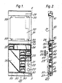
- Figure 1 shows a plan view of an embodiment of a sub-section according to the invention.
- the sub-section comprises a first part 21 defining a matrix of apertures 22 for locating an array of pushbuttons 23.
- the matrix of apertures 22 comprises four columns and five rows. These numbers are arbitary and may be changed depending on the application.
- the pushbuttons 23 are arranged to have a minimum spacing so that there is merely sufficient clearance between them to allow independent operation.
- cover plates 25, 26 are fitted to mask those apertures 22 where a pushbutton is not required and provide a finished surface to the top of the telephone instrument.
- the pushbuttons and cover plates may be blank or may carry legends which may be produced in any convenient fashion, for example printing or engraving.
- the first part 21 and a second part 31 are separated by a ridge 26 and two further ridges 27 and 28 are formed at each end of the sub-section and define the extents of the first part 21 and second part 31.
- the first part 21 is also provided with a number of display devices 30 which are located next to pushbutton positions adjacent to the ridges 26 and 27.
- the second part 31 of the sub-section 20 defines an aperture 32 which extends over a major portion of the second part 31.
- the aperture 32 is provided with four projections 33 for co-operation with spring barbs to locate a cover plate or additional sub-assembly in the aperture 32.
- the aperture 32 extends over the major portion of the second part to allow access to the underside of a sub-assembly, when provided, to enable electrical connection between the sub-assembly and a printed circuit board to be made without inconvenience.
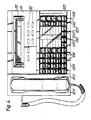
- Figure 2 is a cross-sectional view of the sub-section on line A-A of Figure 1.
- the sub-section 20 is mounted on a printed circuit board 40 by means of barbs 41 which project through co-operating apertures (not shown) in the printed circuit board 40.
- the pushbutton tops 23 are located in the apertures 22 by means of plugs 42 which are a friction fit within the hollow stem 43 of the pushbutton tops 23 and which engage against shoulders 44 of the apertures 22 to prevent the pushbutton tops 23 being displaced from the apertures.
- the printed circuit board 40 is shown broken in the region of the plug 42 merely to enable the fitting of the pushbuttons to be clearly indicated and in practice the printed circuit board extends continuously.
- the plug 42 is biassed against the shoulder 44 by means of an elastomeric dome 45 which includes a conductive pill which short circuits tracks on the printed circuit board when the pushbutton is depressed. Only one dome is shown for reasons of clarity but all operative pushbuttons are provided with such domes.
- the cover plate 24 is located by means of barbs 47 which engage behind the shoulders 44 of appropriate apertures 22.
- the cover plate 25 is, of course, located in the same manner.
- the pushbutton tops are square and have a flat surface which contains a depression 50 which extends over substantially half the top surface area. As can be seen from Figure 4 the pushbutton tops 23 can be mounted with the depression in different orientations the purpose of which will be described hereinafter.
- the display devices 30 comprise a surface mounted light emitting diode 46 and a light guide 30, for example a perspex rod, which is in contact with the light emitting surface of the diode 46 at one end and whose other end provides the visual display at the top surface of the apparatus.
- FIG 3 shows an exploded perspective view of a telephone instrument as an illustration of electrical apparatus using the sub-section of Figures 1 and 2 as part of the construction to form a housing for the apparatus.
- the telephone instrument has a housing comprising a first section 51 in the form of a base section and a second section 52 in the form of a top section.
- the top section 52 is constructed from four sub-sections 53,54,55 and 56, sub-sections 54,55 and 56 being identical to each other and of the form shown in Figures 1 and 2.
- the sub-section 53 is different from the other sub-sections and is designed to locate a handset 57.
- the sub-sections 54, 55 and 56 carry a selected arrangement of pushbuttons 58, and cover plates 59 and 60 which may be blank or may be provided with legends.
- a further sub-assembly 61 carrying pushbuttons 62 and a display device 63 is mounted on the sub-sections 54,55 and 56 by means of barbs 65 which engage with the apertures 64 in the sub-sections.
- the rear of the base section 51 is provided with a plurality of cut outs 68 through which cable entry may be effected.
- the cut outs may have plugs and/or sockets mounted in them or be covered by blanking plates depending on cable entry requirements.
- Telephone and data circuits and components may be mounted on printed circuit boards located by projections 69.
- the sub-sections 54,55,56 are attached to the first or base section 1 by means of screws passing through bosses 66 and pillars 67 ( Figure 3) in the base section into threaded inserts (not shown) located in the ridges 26 and 27 of the sub-sections.
- Various additional or alternative methods of connecting the base and top sections would be readily apparent to those skilled in the art. For example horizontally extending lugs could be formed on the ridge 28 which engage in slots provided in the rear of the base section. Alternatively adhesives could be used, particularly with simple instruments where a replacement rather than repair philosophy was employed.
- a telephone instrument range offering a variety of different facilities can be constructed using one or more sub-sections as described with reference to Figures 1 and 2.
- the pushbuttons By arranging the pushbuttons to cover the spaces between the apertures of the array and by mounting cover plates in the apertures where no pushbuttons are required a finished, visually attractive, housing can be provided using a minimum number of basic parts.
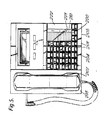
- Figure 4 shows a plan view of a telephone instrument similar to that shown in Figure 3.
- the telephone instrument shown in Figure 4 comprises a handset 107 mounted in a handset sub-section 103 and three indentical sub-sections 104, 105 and 106 which carry a plurality of pushbuttons 108, a cover plate 110 having spaces 120 for writing addresses for repertory dialling or call transfer and indicator devices 121 for indicating the address operated by a pushbutton depression or of a received call, a blank cover plate 122, and a further sub-assembly 111 carrying further pushbuttons 112 and a display unit 113.
- the pushbuttons 108 are of the same form as the pushbuttons 23 and the two columns immediately to the left of the cover plate 110 have their tops turned through 180 degrees with respect to each other. This enables the addresses written on the cover plate to be spaced at half the spacing of the pushbuttons which relate to those addresses, the depressions 50 indicating the address associated with a particular pushbutton. A similar arrangement is used in the two columns to the right of the cover plate 110 for the same purpose.
- the telephone instrument described with reference to Figure 4 may be assembled as illustrated in Figure 3 and uses the sub-section as illustrated in Figures 1 and 2.
- Figure 5 shows a plan view of a telephone instrument having fewer facilities than that shown in Figure 4.
- the instrument shown in Figure 5 comprises a handset section 203 carrying a handset 207 and two identical sub-sections 204 and 205.
- the first sub-section 4 carries an array of pushbuttons 208 while the second sub-section carries a number of pushbuttons 208, a cover plate 210 which has spaces for addresses 220 and indicators 221 and a plain spacer 222.
- the telephone instrument shown in Figure 5 is constructed from the same sub-sections as that shown in Figure 4.
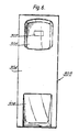
- FIG 6 shows a plan view of a handset sub-section suitable for use in the telephone instruments shown in Figures 3, 4 and 5.
- the handset sub-section 303 comprises a rectangular plate 304 provided with two recesses 305 and 306.
- the recesses 305 and 306 are spaced and dimensioned to receive the mouth and ear pieces of the telephone handset.
- the instruments shown are designed for desk top mounting and the handset is kept in position by gravity. However, if wall mounting was desired with the handset lying substantially vertically rather than horizontally this could be achieved by appropriate design of the shape of the mouth or ear piece and the recesses.
- the recess 305 is provided with an aperture 307 through which the hook switch projects so that it can be operated by replacing the handset on the sub-section.
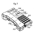
- Figure 7 shows a perspective view of a telephone instrument which comprises a top section 701, a bottom section 702, and a hand set 703 which rests on a hook switch 704.
- the top section 701 comprises a sub-section as shown in Figures 1 and 2 and is provided with an array of pushbuttons 705 which cover the second part 31 of the sub-section.
- the first part 21 of the sub-section is covered by a sub-assembly which comprises a cover plate 706 which carries two pushbuttons 707 and 708 and a display device 709.
- the cover plate 706 will not carry the pushbuttons or display device, but may for example carry a label indicating the telephone number.
- the array of pushbuttons 705 will comprise ten pushbuttons, the vacant positions of the array of apertures then being covered by cover plates which may be formed by dummy pushbutton heads or may be a single piece plate covering two or more apertures.
- a range of compact telephone instruments offering a range of facilities can be constructed using a sub-section such as that shown in Figures 1 and 2 as the top section of the housing to mount the various pushbutton and cover plate combinations required.
- Electrical apparatus other than telephone instruments can be constructed using a sub-assembly according to the invention wherever a variety of functions may be required to provide a range of apparatus.
- Examples of such apparatus include personal computers, data terminals, calculators, radios.
Landscapes
- Engineering & Computer Science (AREA)
- Signal Processing (AREA)
- Telephone Set Structure (AREA)
- Casings For Electric Apparatus (AREA)
- Tires In General (AREA)
- Acyclic And Carbocyclic Compounds In Medicinal Compositions (AREA)
Applications Claiming Priority (2)
| Application Number | Priority Date | Filing Date | Title |
|---|---|---|---|
| GB858524843A GB8524843D0 (en) | 1985-10-09 | 1985-10-09 | Telephone instrument |
| GB8524843 | 1985-10-09 |
Publications (2)
| Publication Number | Publication Date |
|---|---|
| EP0218296A2 true EP0218296A2 (de) | 1987-04-15 |
| EP0218296A3 EP0218296A3 (de) | 1989-02-22 |
Family
ID=10586392
Family Applications (3)
| Application Number | Title | Priority Date | Filing Date |
|---|---|---|---|
| EP86201683A Withdrawn EP0218294A3 (de) | 1985-10-09 | 1986-09-30 | Fernsprecher |
| EP86201684A Expired - Lifetime EP0218295B1 (de) | 1985-10-09 | 1986-09-30 | Fernsprecher |
| EP86201685A Ceased EP0218296A3 (de) | 1985-10-09 | 1986-09-30 | Baustein für einen elektrischen Apparat und elektrischer Apparat mit solchem Baustein |
Family Applications Before (2)
| Application Number | Title | Priority Date | Filing Date |
|---|---|---|---|
| EP86201683A Withdrawn EP0218294A3 (de) | 1985-10-09 | 1986-09-30 | Fernsprecher |
| EP86201684A Expired - Lifetime EP0218295B1 (de) | 1985-10-09 | 1986-09-30 | Fernsprecher |
Country Status (6)
| Country | Link |
|---|---|
| US (2) | US4773090A (de) |
| EP (3) | EP0218294A3 (de) |
| JP (3) | JPS6292557A (de) |
| CA (2) | CA1267739A (de) |
| DE (1) | DE3688351T2 (de) |
| GB (1) | GB8524843D0 (de) |
Cited By (1)
| Publication number | Priority date | Publication date | Assignee | Title |
|---|---|---|---|---|
| FR2690589A1 (fr) * | 1992-04-24 | 1993-10-29 | Alcatel Business Systems | Appareil électronique à touches et afficheur associés. |
Families Citing this family (36)
| Publication number | Priority date | Publication date | Assignee | Title |
|---|---|---|---|---|
| USD304727S (en) | 1988-05-23 | 1989-11-21 | Ag Communication Systems Corporation | Base housing for a multi-feature telephone call processor |
| USD304717S (en) | 1988-05-23 | 1989-11-21 | Ag Communication Systems Corporation | Base housing for a multi-feature telephone call processor |
| JPH01319349A (ja) * | 1988-06-21 | 1989-12-25 | Matsushita Graphic Commun Syst Inc | 画像通信装置の交換カバーとその交換方法 |
| USD325738S (en) | 1988-06-23 | 1992-04-28 | Contel Ipc, Inc. | Multi-module trader telephone installation |
| USD309138S (en) | 1988-09-15 | 1990-07-10 | Solac Telecom, S.A. | Telephone set with handset telephone and stand therefor having keyboard and speakerphone |
| USD308680S (en) | 1988-09-28 | 1990-06-19 | Italtel Telematica S.P.A. | Control console set for telephone exchanges |
| USD311918S (en) | 1988-12-06 | 1990-11-06 | Matra Communication | Telephone set |
| USD306859S (en) | 1989-01-06 | 1990-03-27 | Northern Telecom Limited | Add-on module for a homogeneous unit telephone set |
| US5237608A (en) * | 1989-01-30 | 1993-08-17 | Siemens Aktiengesellschaft | Telephone station having a housing with electrostatic protection |
| USD310524S (en) | 1989-02-17 | 1990-09-11 | Hitachi, Ltd. | Telephone station set |
| USD313235S (en) | 1989-03-03 | 1990-12-25 | Meisei Electric Co., Ltd. | Telephone apparatus |
| US5144302A (en) * | 1989-04-04 | 1992-09-01 | Apple Computer, Inc. | Modular keyboard |
| USD307009S (en) | 1989-04-20 | 1990-04-03 | Northern Telecom Limited | Base for a telephone set |
| USD312459S (en) | 1989-05-02 | 1990-11-27 | Iwatsu Electric Company, Ltd. | Telephone set |
| USD320797S (en) | 1989-07-13 | 1991-10-15 | Meisei Electric Co., Ltd. | Telephone instrument set |
| JPH0756529Y2 (ja) * | 1989-10-21 | 1995-12-25 | 株式会社東芝 | 卓上・壁掛兼用電話機 |
| EP0442467B1 (de) * | 1990-02-15 | 1997-10-29 | Hitachi Telecom Technologies, Ltd. | Installationsstruktur für Handelspult |
| USD327065S (en) | 1990-02-20 | 1992-06-16 | Toa Kabushiki Kaisha/Toa Corporation | Telephone set |
| USD338890S (en) | 1990-12-14 | 1993-08-31 | Mitel Corporation | Telephone handset |
| DE9016975U1 (de) * | 1990-12-17 | 1991-03-07 | Deutsche Fernsprecher Gesellschaft Mbh Marburg, 3550 Marburg | Optische Anzeige in der Sichtöffnung insbesondere eines Fernsprechapparat-Gehäuses |
| DE69321521T2 (de) * | 1992-06-25 | 1999-03-04 | Rolm Systems | Lichtleiter von hoher Durchlässigkeit in geringem Abstand zu einer Funktionstaste |
| USD352943S (en) | 1993-02-24 | 1994-11-29 | Premier Telecom Products, Inc. | Telephone set |
| USD348669S (en) | 1993-02-24 | 1994-07-12 | Premier Telecom Products, Inc. | Telephone set |
| USD352942S (en) | 1993-02-24 | 1994-11-29 | Premier Telecom Products, Inc. | Telephone set |
| USD411534S (en) | 1998-08-07 | 1999-06-29 | Northern Telecom Limited | Internet telephone |
| US6111207A (en) * | 1999-06-30 | 2000-08-29 | Hewlett-Packard Company | Kit for multi-configurable control panel design for office equipment |
| KR100359519B1 (ko) * | 2000-03-16 | 2002-10-31 | 주식회사 동남 실리콘 | 키패드 일체형 통신기기용 전면 커버 |
| DE20021326U1 (de) * | 2000-12-16 | 2001-05-31 | QIAGEN GmbH, 40724 Hilden | Vorrichtung zur Aufnahme von Proben |
| DE10140337B4 (de) * | 2001-08-16 | 2005-02-24 | Siemens Ag | Elektronisches Endgerät |
| JP2004235736A (ja) * | 2003-01-28 | 2004-08-19 | Nec Infrontia Corp | ボタン電話機及びボタン電話システム |
| US7284120B2 (en) | 2003-11-17 | 2007-10-16 | Lenovo (Singapore) Pte. Ltd. | Method and system for allowing a system under test (SUT) to boot a plurality of operating systems without a need for local media |
| US7054700B2 (en) * | 2003-11-17 | 2006-05-30 | Lenovo Pte. Ltd. | Method and system for efficient order processing in a manufacturing environment |
| GB0405790D0 (en) * | 2004-03-15 | 2004-04-21 | Mitel Networks Corp | Universal microphone array stand |
| USD556728S1 (en) * | 2005-07-15 | 2007-12-04 | Thomson Licensing S.A. | Telephone |
| US7853926B2 (en) * | 2005-11-21 | 2010-12-14 | International Business Machines Corporation | Automated context-sensitive operating system switch |
| JP4585499B2 (ja) * | 2006-08-30 | 2010-11-24 | 株式会社東芝 | パネル取り付け構造、パネル取り付け方法および電話機 |
Family Cites Families (25)
| Publication number | Priority date | Publication date | Assignee | Title |
|---|---|---|---|---|
| DE1223889B (de) * | 1964-04-24 | 1966-09-01 | Siemens Ag | Fernsprechteilnehmergeraet |
| DE1487428C3 (de) * | 1966-05-10 | 1974-06-27 | Siemens Ag, 1000 Berlin Und 8000 Muenchen | Fernsprechteilnehmergerät |
| US3521008A (en) * | 1966-10-31 | 1970-07-21 | Northern Electric Co | Telephone instrument |
| AT297807B (de) * | 1969-03-06 | 1972-04-10 | Kapsch Telephon Telegraph | Fernsprechapparat nach einem Baukastensystem |
| CA970086A (en) * | 1973-04-06 | 1975-06-24 | Northern Electric Company | Interconnector for telephone units |
| US3916103A (en) * | 1973-04-09 | 1975-10-28 | Northern Electric Co | Interconnector for telephone units |
| US3941951A (en) * | 1974-05-14 | 1976-03-02 | Bell Telephone Laboratories, Incorporated | Telephone stand |
| US4072840A (en) * | 1974-10-31 | 1978-02-07 | Litton Business Systems, Inc. | Removable keyboard switch |
| US4092527A (en) * | 1977-01-31 | 1978-05-30 | Texas Instruments Incorporated | Calculator with interchangeable keyset |
| CA1102767A (en) * | 1978-03-15 | 1981-06-09 | Decca Limited | Illuminated panels |
| US4291201A (en) * | 1979-04-09 | 1981-09-22 | American Telecommunications Corporation | Push-button dial assembly for telephones |
| US4284855A (en) * | 1979-08-22 | 1981-08-18 | Northern Telecom, Inc. | Base for telephone set, for alternative desk and wall mounting |
| DE3007239C2 (de) * | 1980-02-27 | 1985-02-07 | Standard Elektrik Lorenz Ag, 7000 Stuttgart | Tastatur mit einer Vielzahl von Tastengliedern |
| US4394545A (en) * | 1980-03-11 | 1983-07-19 | Bell Telephone Laboratories, Incorporated | Construction of a telephone instrument |
| JPS6052758B2 (ja) * | 1980-09-20 | 1985-11-21 | 参天製薬株式会社 | 複素三環性化合物 |
| US4375584A (en) * | 1980-10-06 | 1983-03-01 | Siemens Corporation | Modular telephone keyset structure |
| GB2086804B (en) * | 1980-11-04 | 1984-08-22 | Standard Telephones Cables Ltd | Keyblock assembly |
| US4385212A (en) * | 1981-10-05 | 1983-05-24 | Bell Telephone Laboratories Incorporated | Expandable communication terminal housing |
| DE3142414A1 (de) * | 1981-10-26 | 1983-05-05 | Siemens AG, 1000 Berlin und 8000 München | Tastatur fuer kommunkationsendgeraete |
| US4481587A (en) * | 1981-12-24 | 1984-11-06 | Pitney Bowes Inc. | Apparatus for providing interchangeable keyboard functions |
| DE3211479A1 (de) * | 1982-03-29 | 1983-09-29 | Siemens AG, 1000 Berlin und 8000 München | Tastatur fuer fernsprechgeraete |
| US4517420A (en) * | 1983-04-20 | 1985-05-14 | Northern Telecom Limited | Integral cup and hookswitch actuator for a telephone set |
| USD282740S (en) | 1983-05-19 | 1986-02-25 | Rood Robert M | Telephone set |
| JPS6089228A (ja) * | 1983-10-19 | 1985-05-20 | Matsushita Electric Ind Co Ltd | キ−ボ−ド |
| US4581495A (en) * | 1984-05-02 | 1986-04-08 | Buscom Systems Inc. | Modular telephone housing |
-
1985
- 1985-10-09 GB GB858524843A patent/GB8524843D0/en active Pending
-
1986
- 1986-09-30 EP EP86201683A patent/EP0218294A3/de not_active Withdrawn
- 1986-09-30 EP EP86201684A patent/EP0218295B1/de not_active Expired - Lifetime
- 1986-09-30 EP EP86201685A patent/EP0218296A3/de not_active Ceased
- 1986-09-30 DE DE86201684T patent/DE3688351T2/de not_active Expired - Fee Related
- 1986-10-02 CA CA000519630A patent/CA1267739A/en not_active Expired
- 1986-10-02 CA CA000519631A patent/CA1262194A/en not_active Expired
- 1986-10-07 JP JP61237266A patent/JPS6292557A/ja active Pending
- 1986-10-08 JP JP61238207A patent/JPS62142447A/ja active Pending
- 1986-10-09 US US06/916,918 patent/US4773090A/en not_active Expired - Fee Related
- 1986-10-09 JP JP61239387A patent/JPS62161239A/ja active Pending
-
1987
- 1987-12-23 US US07/139,090 patent/US4868875A/en not_active Expired - Fee Related
Cited By (1)
| Publication number | Priority date | Publication date | Assignee | Title |
|---|---|---|---|---|
| FR2690589A1 (fr) * | 1992-04-24 | 1993-10-29 | Alcatel Business Systems | Appareil électronique à touches et afficheur associés. |
Also Published As
| Publication number | Publication date |
|---|---|
| EP0218294A2 (de) | 1987-04-15 |
| JPS62142447A (ja) | 1987-06-25 |
| EP0218295B1 (de) | 1993-04-28 |
| EP0218296A3 (de) | 1989-02-22 |
| JPS6292557A (ja) | 1987-04-28 |
| EP0218295A2 (de) | 1987-04-15 |
| US4868875A (en) | 1989-09-19 |
| EP0218294A3 (de) | 1989-02-15 |
| DE3688351T2 (de) | 1993-10-28 |
| CA1262194A (en) | 1989-10-03 |
| US4773090A (en) | 1988-09-20 |
| EP0218295A3 (en) | 1989-02-22 |
| JPS62161239A (ja) | 1987-07-17 |
| CA1267739A (en) | 1990-04-10 |
| GB8524843D0 (en) | 1985-11-13 |
| DE3688351D1 (de) | 1993-06-03 |
Similar Documents
| Publication | Publication Date | Title |
|---|---|---|
| US4773090A (en) | Sub-assembly for electrical apparatus and electrical apparatus including such a sub-assembly | |
| US4540858A (en) | Modular switch unit with snap-in base, separate modular switch unit and cover coded switch actuating interior lugs | |
| US4621373A (en) | Control surface for a trunking personal radio | |
| US3627930A (en) | Dial-in-handset telephone assembly | |
| RU2204871C2 (ru) | Защита от электростатического разряда в переносном устройстве связи | |
| US4002892A (en) | Portable calculator | |
| JP2937409B2 (ja) | フロントパネル・アセンブリ | |
| US4160886A (en) | Keyboards and methods of making keyboards | |
| US4132877A (en) | Removable keyboard switch | |
| US4231098A (en) | Casing of electronic calculators | |
| GB1560313A (en) | Modular housing units for containing electronic apparatus | |
| EP0232137A2 (de) | Drucktastenschalter mit veränderbarer Bezeichnung | |
| US5734137A (en) | Universal keypad assembly | |
| GB1581695A (en) | Modular housing means for electrical and electronic components | |
| GB2100517A (en) | Electric push button switch | |
| US20240345664A1 (en) | Through Hole Keyboard | |
| US3549783A (en) | Modular component assembly facilitating heat dissipation | |
| US4349286A (en) | Keyboard assembled from individual keys | |
| GB2230740A (en) | Modular keyboard | |
| US4124313A (en) | Keyboard assembly | |
| US4181964A (en) | Integrated electronics assembly on a plastic chassis | |
| EP0712224B1 (de) | Handelspult | |
| FI80360B (fi) | Knappskydd foer en i ett hus anordnad knappsats. | |
| US4202640A (en) | Keyboard assembly | |
| US4647728A (en) | Programming switch assembly for communication terminals |
Legal Events
| Date | Code | Title | Description |
|---|---|---|---|
| PUAI | Public reference made under article 153(3) epc to a published international application that has entered the european phase |
Free format text: ORIGINAL CODE: 0009012 |
|
| AK | Designated contracting states |
Kind code of ref document: A2 Designated state(s): BE DE FR GB IT SE |
|
| RAP3 | Party data changed (applicant data changed or rights of an application transferred) |
Owner name: N.V. PHILIPS' GLOEILAMPENFABRIEKEN Owner name: PHILIPS ELECTRONIC AND ASSOCIATED INDUSTRIES LIMIT |
|
| PUAL | Search report despatched |
Free format text: ORIGINAL CODE: 0009013 |
|
| AK | Designated contracting states |
Kind code of ref document: A3 Designated state(s): BE DE FR GB IT SE |
|
| 17P | Request for examination filed |
Effective date: 19890814 |
|
| 17Q | First examination report despatched |
Effective date: 19911104 |
|
| RAP3 | Party data changed (applicant data changed or rights of an application transferred) |
Owner name: N.V. PHILIPS' GLOEILAMPENFABRIEKEN Owner name: PHILIPS ELECTRONICS UK LIMITED |
|
| STAA | Information on the status of an ep patent application or granted ep patent |
Free format text: STATUS: THE APPLICATION HAS BEEN REFUSED |
|
| 18R | Application refused |
Effective date: 19931231 |
|
| RIN1 | Information on inventor provided before grant (corrected) |
Inventor name: GOATMAN, MICHAEL CHARLESC/O TMC LTD. |